@"Stephen Moraco" said:
@evanh, what is the current state with v1.3.0 vs. your older card? Is the logic working?
I've done more reading of the spec and found the answer. Turns out there is a minimum of 1 byte gap and these cards are following the spec correctly. The timing diagram I posted above should have but doesn't specify the timing of relevance, Nrc. It is listed in the table but has it's own separate diagram:
Sorry for not just uploading the PDF itself. It's one I found in a Web search that is not the free edition.
I suppose, to be fair, it's not clear, from the diagram at least, if Nrc holds true after CS rises. CS high could be considered a reset so then my previous interpretation would hold. It's a little fuzzy so not surprising different manufacturers might have interpreted different ways.
Either way, it's clear the driver has to make the allowance for Nrc holding true irrespective of CS. And the best solution is to, like Flexspin's sdmm.c driver, combine it with the busy check.
@"Stephen Moraco" said:
@evanh, what is the current state with v1.3.0 vs. your older card? Is the logic working?
Every time you post an update at the moment I have to redo a huge number of debug deletes so that the important parts can report anything. Otherwise I just get compile errors of too big debug.
@evanh said:
Every time you post an update at the moment I have to redo a huge number of debug deletes so that the important parts can report anything. Otherwise I just get compile errors of too big debug.
It kind of begs the question of how have you been getting any reporting yourself, Stephen?
I am very supportive of this effort and appears off to great start.
Keep it up @"Stephen Moraco"
8.3 filenames is a serious limitation. But directory support helps a lot with that. Should be fine. FatFs can do long filenames but like triples the memory usage
I’m crazy backed up in projects but will prioritize testing this…
One minor thing to examine is support for RTC for file dating.
@evanh said:
Every time you post an update at the moment I have to redo a huge number of debug deletes so that the important parts can report anything. Otherwise I just get compile errors of too big debug.
It kind of begs the question of how have you been getting any reporting yourself, Stephen?
Augh! That is painful. The latest release, v1.3.2, now has DEBUG_MASK and "CHANNEL"s for debug output. Set the mask to a new value, recompile, and only the new selected debug channels are compiled into your code. Should be much easier. This is all documented.
I started with driver debug only, then eventually it became stable enough that I moved to disabling debug in the driver and pushing some critical state through the caller <-> backend COG interface and just reporting it via debug in the calling program. All the regression tests do this.
@Rayman said:
One minor thing to examine is support for RTC for file dating.
Useful idea. We need to brainstorm a bit about how to support this. Pretty complicated trying to support RTC devices. Pass a creation time through the file create/write method; maybe have a set date/time call for the driver to keep it updated, and use this for file creation/modification? Maybe let the app maintain the current date/time and pass a reference to the driver for use in file creation/modification? Any other ideas?
FYI- (if my understanding is correct) our FAT32 directory entries can contain (all local date time, not utc):
Stephen,
I just noticed you've made an incorrect note in the source comments about ManAtWork's clock polarity reference material. Clock mode 0 is not a necessity at all. SPI slave devices that accept clock mode 0 (CPOL=0 and CPHA=0) are also happy to accept clock mode 3 (CPOL=1 and CPHA=1). In fact bit-bashed master implementations on microcontrollers are rarely precisely mode 0 or mode 3 but somewhere in between. I regularly write routines that explicitly take advantage of this flexibility to allow higher clock rates to be used.
Now, when it comes to the Prop2 boot pins, P58/P59/P60/P61, there is a good reason to always use CPOL=1, and therefore cmode 3. The same four pins are used for both the SD card slot and the soldered Flash EEPROM chip. The difference being SCLK and CS are swapped. But that means that a clock low on one is a chip-select on the other. Things are much less likely to get into a confused state between them if the clock idles high instead of low. Hence why ManAtWork did it the way he did.
@evanh said:
Every time you post an update at the moment I have to redo a huge number of debug deletes so that the important parts can report anything. Otherwise I just get compile errors of too big debug.
Augh! That is painful. The latest release, v1.3.2, now has DEBUG_MASK and "CHANNEL"s for debug output. Set the mask to a new value, recompile, and only the new selected debug channels are compiled into your code. Should be much easier. This is all documented.
@Rayman said:
One minor thing to examine is support for RTC for file dating.
Useful idea. We need to brainstorm a bit about how to support this. Pretty complicated trying to support RTC devices. Pass a creation time through the file create/write method; maybe have a set date/time call for the driver to keep it updated, and use this for file creation/modification? Maybe let the app maintain the current date/time and pass a reference to the driver for use in file creation/modification? Any other ideas?
FYI- (if my understanding is correct) our FAT32 directory entries can contain (all local date time, not utc):
I think an API for getting time/date only from the RTC is the way to go. People have lots of different RTC devices and you don't want to try to code that part into the SD driver. The only need from the SD driver to a timing device is to access the time/date in some standardized format. Any typical i2c/SPI RTC devices or other timing method (GPS uart) could be then supported by the end users if they implement the API. Mainly requires a fallback when the device is not present and timing is unsupported. Using 1 JAN 1970 12:00am etc. Even just the P2 clock ticks since startup might be somehow partially usable at least as an offset for a given session.
Just a couple of thoughts. Wouldn't it be better to just pass the datetime? My implementation actually uses an NTP server to get the current datetime and sets an offset from the P2 boot time (getsec) to determine the current date time. (No RTC needed)
If you simply pass the datetime (through whatever format is easiest for the SD driver) using a custom now() method could be used to pass datetime for creation and modifications regardless of where the time is actually derived (RTC,NTP,GPS,etc).
@ke4pjw said:
Just a couple of thoughts. Wouldn't it be better to just pass the datetime? My implementation actually uses an NTP server to get the current datetime and sets an offset from the P2 boot time (getsec) to determine the current date time. (No RTC needed)
Yes I meant that too - my post was poorly worded above perhaps. The simple API can get the date/time from ANY device, there should be no HW dependency and network time is also feasible. The User just implements the required API.
Maybe with Spin2 you could pass some kind of method pointer to the driver for date/time?
With a null pointer being default that wouldn't get called, or just return something default based on clock tics?
@"Stephen Moraco" Claude swapped out FSRW FAT32.spin2 with your driver for me easy peasy. I have not done a full regression test, but the config reads from the SD card and the web pages are served up. Simply amazing! I had to upload the most recent version of my code and a zip of your driver. I used this prompt:
Would you be capable of changing the filesystem object ( FS ) that the Blitzen 24 uses to access the SD card to use IronSheeps's SD card driver located at https://github.com/ironsheep/P2-uSD-FAT32-FS
Below is the log of the whole process. Simply amazing!
ok, here's my current thinking on uSD filesystem upgrades:
Add call to set date/time, cog track time from there until next date/time set. If it is set, file creations/modifications will be set. Last access deemed too costly (constantly rewriting dir. sectors), so not enabling at this time.
Add a non-blocking form of calls for all file operations. You check for a transfer complete. This is an alternative use model. Choose the one that best fits your application. Also, mix and match as your application needs.
Develop a means to use the dead time for the background cog. When not using the filesystem, use the cog as an overall application resource, but the filesystem takes priority. Studying patterns for implementing this now. We'll have discussions on this in this thread as I come up with ideas/approaches.
As always, any improvements made here will also make it into the dual driver.
@"Stephen Moraco" So, now that you've explained that this driver is all in Spin2 with inline assembly, have a question... Could this be run from the main cog, without invoking a new cog?
Wondering because sometimes the main cog isn't doing all that much and sometimes only need uSD driver occasionally, maybe start up only...
The uSD filesystem properly dismounts the card, leaving it in a state where the P2 can boot from the same SD card. Additionally, a couple of bugs that exist in FAT32.spin2 that do not properly update filesize and leave the filesystem in an inconsistent state when unexpectedly powered off do not occur with this object.
Windows does not want to perform a FSCK on the SD card after it is removed from the P2 when using this object.
My code transverses directories and the uSD filesystem properly transverses those directories.
File and Directory creations and modification dates are valid and have a date of January 27, 2009 06:00 AM (At least that is what is displayed on my machine in CDT)
The uSD filesystem appears to have slightly more performance.
Blitzen 24 was converted to this object via CLaude without any code tweeking required by me. It just works and it works better than FAT32.spin2.
Additional observation: Often with FAT32.spin I would get MD5 checksum errors of the files I download from Azure blob storage. I compare the MD5 of what Azure tells me with what was written to the SD card. I have not received a MD5 mismatch while testing.
@ke4pjw said:
Additional observation: Often with FAT32.spin I would get MD5 checksum errors of the files I download from Azure blob storage. I compare the MD5 of what Azure tells me with what was written to the SD card. I have not received a MD5 mismatch while testing.
What driver were you using? If it was sdspi_bashed2.spin2 then that would explain your problems. That driver is notable flaky at writing data to the SD card. I fixed up its most glaring issues and named it sdspi_bashed3.spin2 a year or two back.
I was using sdspi_with_audio.spin2. At the time it was the only one that worked reliably with PropTool. I had high hopes for the bashed drivers, but gave up. I did not try yours, but a free COG would be nice
There is the option of libc.spin2. That provides many useful functions, including C file management, as one large spin2 object. And its cogless to boot. Only requirement is it needs to be compiled with Flexspin.
EDIT: I just had a squiz at sdspi_with_audio.spin2 and, although not identical to sdspi_bashed2.spin2, it has the same flaws. Namely it just doesn't really do busy checks. So, yeah, it'll have the same issues.
@evanh said:
EDIT: I just had a squiz at sdspi_with_audio.spin2 and, although not identical to sdspi_bashed2.spin2, it has the same flaws. Namely it just doesn't really do busy checks. So, yeah, it'll have the same issues.
Should probably try backporting the bashed3 changes to that... (do you know where you posted it still? Otherwise need to go on a safari.)
I built the with_audio driver for the Spin Hexagon P2 port. That only ever writes its 512 byte highscore file, so I guess that is why it mostly works. Getting it to reliably read was already a big deal in those early days. Though I do remember having bugs sometimes where the audio would not start playing correctly, maybe related...
@"Stephen Moraco" I don't know which direction you are taking regarding the datetime for the object, but maybe this would be helpful. I use getsec + known unixbootime to know what the current time is based on a Unix timestamp. Below is a link to my NTP client. There are some useful Spin2 methods in there for displaying the datetime in human readable form based on Unix timestamp.
@evanh said:
EDIT: I just had a squiz at sdspi_with_audio.spin2 and, although not identical to sdspi_bashed2.spin2, it has the same flaws. Namely it just doesn't really do busy checks. So, yeah, it'll have the same issues.
Should probably try backporting the bashed3 changes to that... (do you know where you posted it still? Otherwise need to go on a safari.)
Long forgotten but I do have my working copy. It's dated Nov 2024 which nicely lines up with when the 4-bit SD mode driver was becoming stable and I was doing lots of speed tests then. I changed the init() interface at the last moment to make it cleaner when swapping between drivers. Easy to change back.
@evanh said:
Long forgotten but I do have my working copy. It's dated Nov 2024 which nicely lines up with when the 4-bit SD mode driver was becoming stable and I was doing lots of speed tests then. I changed the init() interface at the last moment to make it cleaner when swapping between drivers. Easy to change back.
oops, don't have bashed2 anymore (found it), either and the code structure is too different to see the problem immediately
EDIT: So what you're saying is, the busy check should not be at the end of a write, but before issuing a command? Because the audio driver does have a ready check after a block write.
And that is also how the P1 tinySDDA driver that it was to jump in for does it, which has been totally fine (though with caveat that Spin Hexagon still only ever writes 512 byte score files)
@Wuerfel_21 said:
EDIT: So what you're saying is, the busy check should not be at the end of a write, but before issuing a command? Because the audio driver does have a ready check after a block write.
I didn't analyse if that was a vital config but pretty much yes. I've copied how sdmm.cc command sequence does it. That is the more efficient solution anyway since it exits from the driver while the card is known to be in a busy state. Only checking in if more action is requested.
There is a second busy check after CMD24, but before any block data is sent, as well.


Comments
I've done more reading of the spec and found the answer. Turns out there is a minimum of 1 byte gap and these cards are following the spec correctly. The timing diagram I posted above should have but doesn't specify the timing of relevance, Nrc. It is listed in the table but has it's own separate diagram:
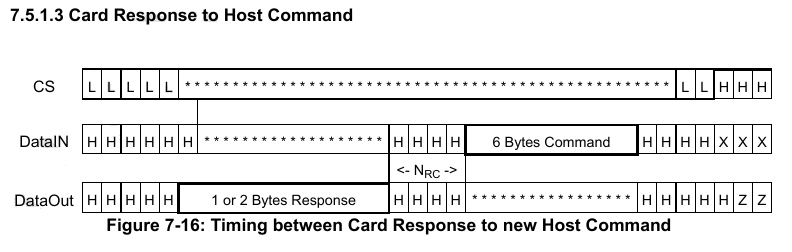
Sorry for not just uploading the PDF itself. It's one I found in a Web search that is not the free edition.
So adding a padding $FF byte at the end of the prior sequence, before rasing CS instead of after lowering CS, should also do the job.
I suppose, to be fair, it's not clear, from the diagram at least, if Nrc holds true after CS rises. CS high could be considered a reset so then my previous interpretation would hold. It's a little fuzzy so not surprising different manufacturers might have interpreted different ways.
Either way, it's clear the driver has to make the allowance for Nrc holding true irrespective of CS. And the best solution is to, like Flexspin's sdmm.c driver, combine it with the busy check.
Every time you post an update at the moment I have to redo a huge number of debug deletes so that the important parts can report anything. Otherwise I just get compile errors of too big debug.
Here's the relevant Adata 16GB card:
So the probeCmd13() is succeeding now. However, such a check is also defunct now that we know the why.
It kind of begs the question of how have you been getting any reporting yourself, Stephen?
I am very supportive of this effort and appears off to great start.
Keep it up @"Stephen Moraco"
8.3 filenames is a serious limitation. But directory support helps a lot with that. Should be fine. FatFs can do long filenames but like triples the memory usage
I’m crazy backed up in projects but will prioritize testing this…
One minor thing to examine is support for RTC for file dating.
Augh! That is painful. The latest release, v1.3.2, now has DEBUG_MASK and "CHANNEL"s for debug output. Set the mask to a new value, recompile, and only the new selected debug channels are compiled into your code. Should be much easier. This is all documented.
I started with driver debug only, then eventually it became stable enough that I moved to disabling debug in the driver and pushing some critical state through the caller <-> backend COG interface and just reporting it via debug in the calling program. All the regression tests do this.
Useful idea. We need to brainstorm a bit about how to support this. Pretty complicated trying to support RTC devices. Pass a creation time through the file create/write method; maybe have a set date/time call for the driver to keep it updated, and use this for file creation/modification? Maybe let the app maintain the current date/time and pass a reference to the driver for use in file creation/modification? Any other ideas?
FYI- (if my understanding is correct) our FAT32 directory entries can contain (all local date time, not utc):
Stephen,
I just noticed you've made an incorrect note in the source comments about ManAtWork's clock polarity reference material. Clock mode 0 is not a necessity at all. SPI slave devices that accept clock mode 0 (CPOL=0 and CPHA=0) are also happy to accept clock mode 3 (CPOL=1 and CPHA=1). In fact bit-bashed master implementations on microcontrollers are rarely precisely mode 0 or mode 3 but somewhere in between. I regularly write routines that explicitly take advantage of this flexibility to allow higher clock rates to be used.
Now, when it comes to the Prop2 boot pins, P58/P59/P60/P61, there is a good reason to always use CPOL=1, and therefore cmode 3. The same four pins are used for both the SD card slot and the soldered Flash EEPROM chip. The difference being SCLK and CS are swapped. But that means that a clock low on one is a chip-select on the other. Things are much less likely to get into a confused state between them if the clock idles high instead of low. Hence why ManAtWork did it the way he did.
DEBUG_MASK is working. Thank you!
I think an API for getting time/date only from the RTC is the way to go. People have lots of different RTC devices and you don't want to try to code that part into the SD driver. The only need from the SD driver to a timing device is to access the time/date in some standardized format. Any typical i2c/SPI RTC devices or other timing method (GPS uart) could be then supported by the end users if they implement the API. Mainly requires a fallback when the device is not present and timing is unsupported. Using 1 JAN 1970 12:00am etc. Even just the P2 clock ticks since startup might be somehow partially usable at least as an offset for a given session.
Just a couple of thoughts. Wouldn't it be better to just pass the datetime? My implementation actually uses an NTP server to get the current datetime and sets an offset from the P2 boot time (getsec) to determine the current date time. (No RTC needed)
If you simply pass the datetime (through whatever format is easiest for the SD driver) using a custom now() method could be used to pass datetime for creation and modifications regardless of where the time is actually derived (RTC,NTP,GPS,etc).
Yes I meant that too - my post was poorly worded above perhaps. The simple API can get the date/time from ANY device, there should be no HW dependency and network time is also feasible. The User just implements the required API.
Maybe with Spin2 you could pass some kind of method pointer to the driver for date/time?
With a null pointer being default that wouldn't get called, or just return something default based on clock tics?
@"Stephen Moraco" Claude swapped out FSRW FAT32.spin2 with your driver for me easy peasy. I have not done a full regression test, but the config reads from the SD card and the web pages are served up. Simply amazing! I had to upload the most recent version of my code and a zip of your driver. I used this prompt:
Below is the log of the whole process. Simply amazing!
https://claude.ai/share/9e4eab98-9b67-4f30-84f6-13e97af39707
@Rayman this might be the easiest way to integrate the new driver into whatever code you were looking at changing.
I am looking forward to trying it out. Thanks.
Saw seek in there and had flashback to where “seek” had some serious edge case flaws in other drivers…
Maybe seeking past end of file was one, don’t really recall much…
Call it a filesystem rather than driver. The driver sits underneath and talks block level ops. There is no files at the driver level.
ok, here's my current thinking on uSD filesystem upgrades:
As always, any improvements made here will also make it into the dual driver.
Are there any more obvious needs?
@"Stephen Moraco" So, now that you've explained that this driver is all in Spin2 with inline assembly, have a question... Could this be run from the main cog, without invoking a new cog?
Wondering because sometimes the main cog isn't doing all that much and sometimes only need uSD driver occasionally, maybe start up only...
BTW: Looked up FatFS notes on exFat and seems license is only needed for commercial products, at least according to them:
https://elm-chan.org/fsw/ff/doc/appnote.html#exfat
I validated the following:
Blitzen 24 was converted to this object via CLaude without any code tweeking required by me. It just works and it works better than FAT32.spin2.
Additional observation: Often with FAT32.spin I would get MD5 checksum errors of the files I download from Azure blob storage. I compare the MD5 of what Azure tells me with what was written to the SD card. I have not received a MD5 mismatch while testing.
Well done @"Stephen Moraco" !!
What driver were you using? If it was
sdspi_bashed2.spin2then that would explain your problems. That driver is notable flaky at writing data to the SD card. I fixed up its most glaring issues and named itsdspi_bashed3.spin2a year or two back.I was using sdspi_with_audio.spin2. At the time it was the only one that worked reliably with PropTool. I had high hopes for the bashed drivers, but gave up. I did not try yours, but a free COG would be nice")
There is the option of libc.spin2. That provides many useful functions, including C file management, as one large spin2 object. And its cogless to boot. Only requirement is it needs to be compiled with Flexspin.
EDIT: I just had a squiz at sdspi_with_audio.spin2 and, although not identical to sdspi_bashed2.spin2, it has the same flaws. Namely it just doesn't really do busy checks. So, yeah, it'll have the same issues.
Should probably try backporting the bashed3 changes to that... (do you know where you posted it still? Otherwise need to go on a safari.)
I built the with_audio driver for the Spin Hexagon P2 port. That only ever writes its 512 byte highscore file, so I guess that is why it mostly works. Getting it to reliably read was already a big deal in those early days. Though I do remember having bugs sometimes where the audio would not start playing correctly, maybe related...
@"Stephen Moraco" I don't know which direction you are taking regarding the datetime for the object, but maybe this would be helpful. I use getsec + known unixbootime to know what the current time is based on a Unix timestamp. Below is a link to my NTP client. There are some useful Spin2 methods in there for displaying the datetime in human readable form based on Unix timestamp.
https://forums.parallax.com/discussion/175966/p2-ntp-client
Whatever epoch you decide on, I recommend using getsec() + known bootime epoc to determine current time. It is a free counter.
Long forgotten but I do have my working copy. It's dated Nov 2024 which nicely lines up with when the 4-bit SD mode driver was becoming stable and I was doing lots of speed tests then. I changed the init() interface at the last moment to make it cleaner when swapping between drivers. Easy to change back.
EDIT: Found it based on the date and topic refresher - https://forums.parallax.com/discussion/comment/1563810/#Comment_1563810
oops, don't have bashed2 anymore (found it), either and the code structure is too different to see the problem immediately
EDIT: So what you're saying is, the busy check should not be at the end of a write, but before issuing a command? Because the audio driver does have a ready check after a block write.
And that is also how the P1 tinySDDA driver that it was to jump in for does it, which has been totally fine (though with caveat that Spin Hexagon still only ever writes 512 byte score files)
I didn't analyse if that was a vital config but pretty much yes. I've copied how sdmm.cc command sequence does it. That is the more efficient solution anyway since it exits from the driver while the card is known to be in a busy state. Only checking in if more action is requested.
There is a second busy check after CMD24, but before any block data is sent, as well.
The principle being don't bother checking until you actually need to know.