

Synchronous Shift In with External Clock - Is there a SIMPLE example?
 Christof Eb.
Posts: 1,545
Christof Eb.
Posts: 1,545
Hi,
to interface P2 with a HM01B0 camera with 1bit interface, I need to shift in from a serial line with an external clock frequency PCLKO of 24MHz. P2 is running at 200MHz. Data has to be written to a buffer in HUB.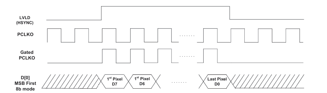
https://www.uctronics.com/download/Datasheet/HM01B0-MWA-image-sensor-datasheet.pdf
The whole procedure to receive a picture can be seen here as a PIO program for Pico, starting from line 148:
https://github.com/ArmDeveloperEcosystem/hm01b0-library-for-pico/blob/main/src/hm01b0.c
I don't think, that I have a chance to do this shifting bit-banging??? Right? Or do I? That would be something like:
wait for HSYNC LO
wait for HSYNC HI
Repeat for all pixels/4:
  Repeat 32 times:
    wait for CLK HI
    wait for CLK LO
    read DATAPIN
    shift DATA
  wrfast DATA to HUB
So my question is, if there is a really SIMPLE example for the %11101 = synchronous serial receive smart mode?
Thanks very much for some hints!
Christof
Comments
Hi Christof,
While I don’t pretend to be an expert on the Pico’s PIO, after reviewing the code and the data sheet it looks to me like you are setting up to read on the wrong clock edge.
I don’t have time to analyze the PIO program fully at the moment, but I think it is possible to produce the simple example you are looking for.
Give this a try -- seems to work.
In this demo I start up a background Spin2 cog and use smart pin sync_tx to simulate sending one 32-bit value (see screenshot from LA). used a set of jumpers on my Eval board to route signals.
Note: the sync_rx function defaults to LSBFIRST so you may have to reverse your data bits before saving to the hub.
Thank you very much!!!
Christof
That's odd: If I look at the diagram, I posted, it seems right to latch with falling edge. But the PIO code is different. Perhaps there is enough delay in the PIO?
smartpins do have some delay, i think 2 or 3 clock ticks. so that won't explain it
polarity of the clock pin might be reversed
or falling edge might be enabled
see
https://p2docs.github.io/pin.html#p-sync-rx
The image sensor data sheet shows the data transition happening while the clock is low, so reading should occur on the rising edge while the data is stable. I don’t know where you got the diagram that you posted.
The diagram is figure 6.8 from page 33 of the data sheet. Polarity of PCLKO can be set via register 0x3068[0].
Perhaps I can try to measure with my oscilloscope, or just try out.
In any case thank you very much for pointing me to this!
Edit: OK, my 70MHz scope is a bit slow for this, but data transition seems to start with falling edge. Jep, reading on rising edge makes sense, whatever that diagram says.
For some reason PCKLO frequency seems "only" to be 12MHz. (?)
You may need to invert the clock input pin for the SYNC_RX. It's in the demo code, but I commented it out.
Yes, the datasheet is broken, use a fast oscilloscope to work out by experiment.
PS: The actual timing info is on pages P47 and P48 of the datasheet, but its numbers are just as screwy as that diagram is. It talks about data latencies longer than the clock period, and inflexibly large setup and hold times that shouldn't even be listed since those are parameters for receive not transmit.
There's no consistency either. The latency on page 47 even if subtracting a clock cycle (88 - 83.3 = 4.7 ns) is still larger than the latency on page 48 (31.2 - 27.8 = 3.4 ns). Doesn't make any sense at all.
I confess that I didn’t read the whole data sheet and skipped straight to page 48. As has been pointed out, some of the timings seem out of whack and so there may be an errata document to look for.
Thanks to Jon! Got first results.
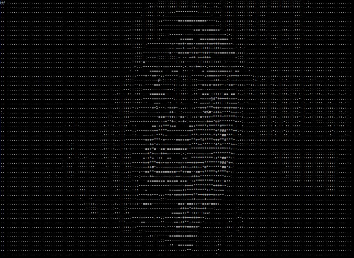
That's supposed to be me:
:-)
I am using this "gated clock mode", so only 3V3, GND, D0, PCLKO, SDL, SCL needed.
Cool!
Very nice :-)
I noticed the gated clock mode, and thought using it along with only watching for rising edges (41.7 ns per PCLK cycle is too much work to check both edges at 200 MHz using waitpat or busy loops), might support a bit bashed solution.