

Entering the EV world
 iseries
Posts: 1,531
iseries
Posts: 1,531
First think I notice was driving past a gas station looking at the gas prices only to realize it doesn't matter.
I am used to pulling up to the gas pump and seeing how much gas and what it cost me. Now I plug it into an outlet at my house and have no idea what I just did. There is no pump fuel gauge or cost to tell me what just happened.
There are devices that can be installed in the power panel that will monitor everything that goes on in your house. Emporia is one of these devices.
I was thing of DIYing it with building a ferrite core and cutting it in half and monitoring with a hall effect sensor. This seems a little much and now looking at a different solution.
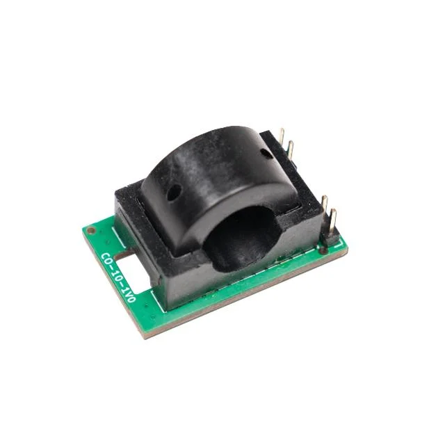
This takes some of the DIY out of the project and make a simple device that outputs 40ma per amp of power.
Now I need to build a program that converts the voltage into amps and displays it or maybe sends the data to my network for processing. I would need to monitor how many amps per hour are used to come up with a cost to charge an EV as we pay for power by the kilowatt hour.
I was thinking that a P2 could easily do this by using the analog feature of the pin with a resistor function added across as the circuit needs an added resistance to measure the voltage.
The only thing is how to measure time.
Comments
This is a simple current transformer? Ok, this is better than the linear hall effect sensor as it doesn't have offset and temperature drift problems. But you should also measure the voltage, say every milli second, and then multiply current times voltage to get power (kW) and then integrate that over time to get energy (kWh). This way you measure true RMS current. Only measuring (average) current will produce errors when there is reactive current, e.g. the power factor is not 1.0.
The unit I am looking at is CTS-CS-CAX-10-050. This unit require 5 volts to power it and returns a voltage based on current flow. Not sure how this works.
If the P2 is running at 200Mhz and I setup a loop to read every millisecond how much drift would there be in an hour?
This sensor has an offset drift of +/-5mV. This sounds not too bad but means +/-0.5A. If you charge your EV say it's 16A @ 400V for 2 hours or 22kWh. But an offset error of 0.5A is 345W so during the rest of the day (22h) this could sum up to an error of 7.5kWh.
Edit: never mind. The actual error is much lower if you do that true RMS calculation a DC error means a power draw for one half period but a feed-back for the other half.
I setup a test program just using a potentiometer to see what the smart pin will read out.
This is the test program:
#include <stdio.h>
#include <propeller.h>
#include <smartpins.h>


#define POWER 20

int main(int argc, char** argv)
{
    int i;

    printf("Starting\n");

    _pinstart(POWER, P_ADC | P_ADC_1X, 13, 0);

    while (1)
    {
        i = _rdpin(POWER);
        printf("Power: %d\n", i);
        _waitms(1000);
    }
}
This is a table of the results. The output reading jumps around so did not get a stable value to use.
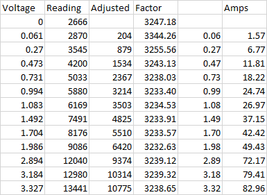
Will have to average the numbers somehow or maybe just divide by 10.
Right now, the unit charges the car at 40 amp at 240 volts or about 9.6Kw per hour and can fully charge the car in under 10 hours.
Based on the owner's manual they recommend only charging the unit to 80% to preserve the life of the batteries. Only charge to 100% on long trips.
Never realized how complicated EV charging station are. While there are only two types of plugs, an AC plug and a DC plug the number of different cars is many.
When you plug your car in the car talks to the charging station and negates what it wants. Some car run at 400 Volts while other can be up to 1,000 Volts.
If the charging station only supplies 400 volts the car uses a buck convert to jump the voltage up to what it needs. It even uses one winding on the BLDC motor as part of the buck converter.
The P2 pin will add at least +- 1mV drift with the best code. Accurate DC measurement with the P2 pins is tricky.
The sensor you linked looks fine. I believe it will give AC output with a 2.5V DC bias.
Have a look at OpenEVSE. That unit uses a current transformer which is read by an ATmega328.
https://github.com/OpenEVSE/OpenEVSE_PLUS/blob/master/OpenEVSE_PLUS_v5.5/OpenEVSE_PLUS_v5.5.pdf It works fairly well. I assume there is a high pass filter in the software to eliminate DC offset.
There is a good chance that the AC current is reported over the CAN bus. Every vehicle is different.
For timing you'll want to use a timer. The documentation has this example:
        GETCT   x               'get initial CT
        ADDCT1  x,#500          'make initial CT1 target

 .loop  WAITCT1                 'wait for CT to pass CT1 target
        ADDCT1  x,#500          'update CT1 target
        DRVNOT  #0              'toggle P0
        JMP     #.loop          'loop to the WAITCT1
This can be done in high level languages too. The code here will run every 500 clock cycles regardless of how long the code inside takes. Using a delay function won't work because it won't compensate for the time it takes to run the actual program. Any crystal oscillator should have enough accuracy for this purpose. If you want to sample every 1mS (I would run faster, like 0.1mS) then the value would be 200000000/1000 = 200000 clock cycles.
Or you could use the ADC smart pin for timing. If you set a sample period of 20000 then waiting for IN to go high will have the same effect.
Now you're getting a taste as to why AC was chosen over DC in the early days of building out electricity distribution. Having just a plain ruggedly built transformer for handling this conversion eliminates so many points of failure.
My current plan right now is to read the sensor every second and sum those values into minutes where I will divide it by 60 to the average voltage.
Convert that value to amps and add that value to hours. Then by multiplying that value by 240 to get watts per hour.
I figure I will need three bucks, Seconds, Minutes, and Hours.
Mike
Change in plans, decided that I could use the raw number coming from the smartpin. With 32-bit number I would not overflow for a couple of days, and I am just looking at a few hours. Conversion to watts though required a little careful math as to not overflow the numbers.
First, I normalize the smartpin reading by subtracting 2666. Then take 60 reading each second to get a minute's worth of numbers. Drop those numbers into an hour and days.
Since I wanted a rolling number of watts just like at the gas pump, I just needed to convert the total reading each second that was being recorded.
Dividing by 3247 get me the actual voltage reading of the smartpin. To get to watts I would divide by .04 or in my case multiple by 25 and the use 240 volts but remove a zero to get 60 and then divide by 3600 removing two zeros to convert from seconds to hours.
I thought about using an eInk display but found the constant update caused a lot of flashing and then thought about using a Nextion display but decided that was over kill for this project.
I decided on the MAX7219 display which actual makes it look like a gas pump as the number change as you refuel the car.

The display will show the watts used as time goes by.
#include <stdio.h>
#include <propeller.h>
#include <smartpins.h>
#include "MAX7219.h"


void average(void *);

#define POWER 20
#define DOUT 50
#define LODA 51
#define CLK  52


int Wait;
volatile int Minutes, Minute;
volatile int Hours, Hour;
volatile int Day;
volatile int TCurrent, Current;
volatile int Mins;
int Stack[2046];
char Buffer[1024];


int main(int argc, char** argv)
{
    int C;
    int i;
    int Power;
    int m;
    int Watts;

    printf("Starting\n");

    MAX_Init(DOUT, CLK, LODA, 8);

    cogstart(average, NULL, Stack, 2046);

    _waitms(1000);

    while (1)
    {
        Power = Current * 1000 / 12988;
        /* 3247 conversion factor to volts */
        /* 60 conversion factor to watts 25(.04) X 240 volts */
        /* 36 number of seconds in an hour 3600 */
        m = TCurrent / 3247 * 60 / 36;
        Watts = Power * 24;

        MAX_Number(m, 0);

        //printf("Mins: %d, Amps*10: %d, Watts: %d, TWatts: %d\n", Mins, Power, Watts, m);
        _waitms(1000);
    }
}


void average(void *par)
{
    int i;
    int d;
    int hrs, mins;
    int mils;

    TCurrent = 0;
    Minutes = 0;
    Hours = 0;

    _pinstart(POWER, P_ADC | P_ADC_1X | P_LOW_15K, 0x0d, 0); // enable ADC with 15K resistance

    _waitms(500);

    hrs = 0;
    Mins = 0;
    while (1)
    {
        mils = _getms();
        /* Get 60 Reading for a Minute */
        for (i=0;i<60;i++)
        {
            Current = _rdpin(POWER) - 2666;
            TCurrent += Current;
            _waitms(999);
        }

        /* Convert Current into Amps per minute */
        Minute = TCurrent;
        Minutes += Minute;

        /* Have full hour now amps per hour */
        if (Mins++ > 59)
        {
            Hour = Minutes;
            Hours = Hour;
            Mins = 0;
            hrs++;
        }

        /* Power for the Day */
        if (hrs > 23)
        {
            Day += Hours;
            Hours = 0;
            Minutes = 0;
            TCurrent = 0;
            hrs = 0;
        }

        Wait = _getms() - mils;
    }

}
As you can see from the picture, I don't have the clamp on device to complete the project. It's on its way.
Mike
The built in
muldiv64()is your friend for preventing overflows. Naming in FlexC is_muldiv64(). I also made a version that rounds to nearest that I callmuldiv65().And of course using floats is also an option.
I finally got the unit in and started testing only to find out the starting voltage of the unit 2.5 Volts.
Looking closer at the spec sheet show that it does indeed start at 2.5 volts and goes up to 4.5 volts.
That's out of range for the ADC and now I need to use a voltage divider to get the voltage into the 0 to 3.3 volt range. I also found out that I cannot use a pull down smartpin resistor in ADC mode. That would have made it easy to insert a series resistor inline.
The spec sheet shows that the typical value for the load resistor is 25K with a min value of 10K. I decided to use two 10K resistors and divide the output voltage in half to make the calculation easier. Instead of 40mv per amp now I only get 20mv per amp.
Hopefully this will be enough resolution to get an accurate reading of the power used.
Maybe I could use a couple of series diodes to drop the voltage by 1 volt.
Mike
Actually, putting the unit in the circuit failed. All my testing was using a DC source, and the EV uses 240 AC.
Putting a scope on the unit with an AC source turns out it only shows the current in one direction, and it shows it as a hump as the voltage and current go up.
Had to change the code to start another cog that just returned the highest voltage within the second. Hopefully this is the right value.
Would hate to have to do some RMS calculations.
Mike
As I said above, you need to sample current and voltage with a rate much higher than the AC frequency (60Hz). If the charger has a PFC (power factor correction, which it should) you can assume that the power faxctor is nearly 1.0 and so the "highest voltage within a second" might work but is not very accurate. The P2 should be powerful enough to sample once per millisecond and calculate the true RMS which will work reliably in all cases.
I did some testing with a Hair dryer since that what I could find. The unit is rated at 1500 watts so should be able to come up with a number since I don't have a real amp meter to clamp on. May have to get one.
Using my handy PropScope with the hair dryer at 50% I get this output

I see that it is only giving me 50% of sine wave with a peek value of 2.85 volts. 2850mv - 2500mv = 350mv divide by 40mv = 8.75 Amps or 6.187 Amps RMS.
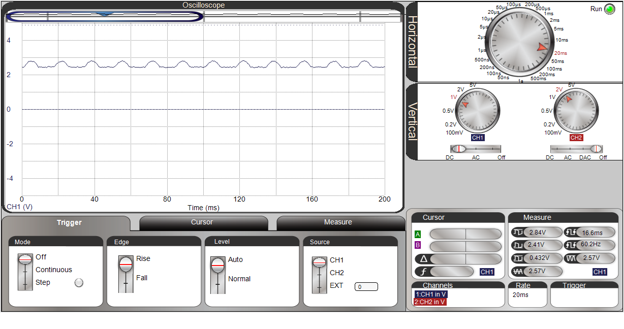
At full power I get this output
Now I get a sine way offset by the 2500mv. With a peek reading of 3070mv - 2500mv = 570mv divide by 40mv = 14.25 Amps or 10.07 Amps RMS.
Since I don't have an Amp meter 1500Watts / 120Volts = 12,5 Amps. A number in between the two values I got.
Well at least I'm getting something. I just need to get my numbers to line up at this point. Don't see a need to measure every millisecond as the RMS value is based on the peak value anyway.
Mike
That's only true for power factor = 1.0 (ie: pure resistive load) and the supply maintains a pure sine wave. But since most loads are not pure resistive and the supply can be quite distorted, you can be sure that using peak as a stand-in for RMS will be wrong.
PS: A nice feature of the Propellers is they can dedicate a whole core to real-time compute and not be burdened.
It looks like that hair dryer uses a diode to get the low heat setting.
It's safe to assume that an EV charger will have power factor correction. It's a requirement.
If you want to just measure the peak, I would suggest you measure minimum and maximum. The current would be calculated from the peak-to-peak value. That way you will avoid the problem of determining what the voltage for zero current is.
Measuring RMS will result in much lower noise in the reading. If you measure peak, that value may be inflated by a few counts due to random noise in the ADC. If you are computing RMS, that inflated peak value will be averaged with many samples that are not inflated with random noise. So its effect will be much smaller.
I have a few problems here.
First with a DC current the unit seems to work just fine but with an AC current the flux is only measured in one direction so 50% of the reading are missing at low current.
If the unit is only measuring current and not voltage should the conversion for current be used which is .35355 and not .7071 to get RMS. In either case the reading that are returned are too high at lower current values and about right at higher current.
I used an inline current sensor on the hair dryer and see that at the low setting it uses 4.67 amps and at the high setting 10.74 amps.
Running the test code, I get 9 amp at the low setting and 14.8 at the high settings. Even using a conversion to RMS these numbers don't match up.
With too few reading it's going to be hard to come up with a conversion factor that I can use to calibrate the readings.
Mike
James will be correct. The two waveform screenshots you posted is telling you that the hair drier is using a single rectifying diode in half power position. The transducer is showing the complete current usage.
That's a pretty shitty way to treat the AC supply but is certainly a cheap solution to get half power.
I finally got around to doing a real test of the unit.
The program works by determining the highest value every second and then sums that value every minute for display.
I added two items to the display so every so often it displays the Current value, Time in minutes, and then the Total Power in watts.
The charging session lasted about 192 minutes and showed I used 28,800 Watts.
The car showed I added 32Kwh. My utility website showed I used about 29Kwh.
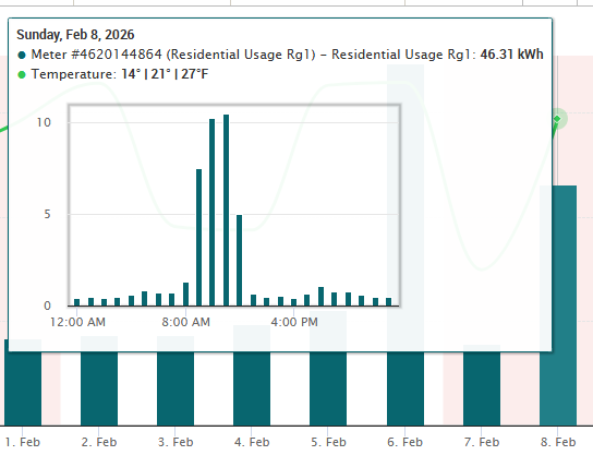
Not sure what value is correct here, but the numbers are close.
In any case it looks like it cost me about $3.00 to add fuel to the car.
I have two version of the program, one for DC current and one for AC.
#include <stdio.h>
#include <propeller.h>
#include <smartpins.h>
#include "MAX7219.h"

//#define DEBUG
#define AC

void average(void *);
void GetADC(void *);


#define POWER 36
#define DOUT 50
#define LODA 51
#define CLK  52


int Wait, Wait2;
volatile int TCurrent, Current;
volatile int Time;
volatile int HighValue;
int Stack[1024];
int Stack2[1024];
char Buffer[1024];


int main(int argc, char** argv)
{
    int i, j;
    int Amps;
    int TWatts;
    int Watts;

#ifdef DEBUG
    printf("Starting\n");
#endif

    MAX_Init(DOUT, CLK, LODA, 8);

    cogstart(average, NULL, Stack, 1024);
    cogstart(GetADC, NULL, Stack2, 1024);

    _waitms(1000);

    i = 0;
    while (1)
    {
        /* 1607 conversion factor to volts X 40mv per amp*/
        Amps = Current * 1000 / 6400;
        /* 1607 conversion factor to volts */
        /* 600 conversion factor to watts 25(.04) X 240 volts */
        /* 36 number of seconds in an hour 3600 */
        TWatts = TCurrent / 1607 * 60 / 36;
        Watts = Amps * 24;


        j = (i++ >> 1) & 0x03;
        if (j == 0)
        {
            MAX_Number(Amps, 2);
            MAX_Digit(8, 11, 0);
        }
        if (j == 2)
        {
            MAX_Number(TWatts, 0);
            MAX_Digit(8, 14, 0);
        }
        if (j == 1)
        {
            MAX_Number(Time, 0);
            MAX_Digit(8, 13, 0);
        }
        i = i & 15;

#ifdef DEBUG
        printf("Mins: %d, Reading: %d, Amps*10: %d, Watts: %d, TWatts: %d\n", Time, Current, Amps, Watts, TWatts);
#endif
        _waitms(1000);
    }
}


void average(void *par)
{
    int i;
    int mils;

    TCurrent = 0;

    _waitms(250);

    HighValue = 0;
    Time = 0;
    while (1)
    {
        mils = _getms();
        /* Get 60 Reading for a Second */
        for (i=0;i<60;i++)
        {
            Current = HighValue - 4069; // offset for device 2.5 volts
#ifdef AC
            Current = Current * 7071 / 10000;
#endif
            HighValue = 0;
            if (Current < 0)
                Current = 0;
            TCurrent += Current;
            _waitms(998);
        }

        if (Current > 0)
            Time++;
        Wait = _getms() - mils;
    }

}

void GetADC(void *par)
{
    int i;
    int h;
    int micro;

    _pinstart(POWER, P_ADC | P_ADC_1X, 13, 0); // enable ADC with

    h = 0;
    while (1)
    {
        micro = _getus();
        while (_pinr(POWER) == 0)
            _waitus(5);
        h = _rdpin(POWER) - 2972;
        if (h > HighValue)
            HighValue = h;
        Wait2 = _getus() - micro;
    }

}
Some more fine tuning is needed but the results look good.
Mike
I don't really understand your timing strategy. You call _waitms(998), _waitms(1000) and waitus(5) at some point but the variables Wait and Wait2 are set but never used.
I think, it is essential to take multiple samples over one full AC cycle (16.6ms for 60Hz or 20ms for 50Hz depending on where you live).
Averaging over several samples taken at 1s intervals might pick up nothing at all if you accidentally catch the zero crossings where the current is always zero. It might work in spite of that but it depends on good luck.
If you take 100 samples equally spaced over 100ms and calculate the average then it's guaranteed to work for both 50 and 60Hz. Min/Max is no good strategy because a single spike caused by noise could result in a false reading.
Wait1 and Wait2 are just to see what the time looks like running through the code. Not used for anything.
AC and DC are based on peak readings. The difference is for AC to calculate the RMS value which is .7071 time the peak voltage of the device.
Taking multiple reading of the sine wave would mean I would have to calculate the RMS value some other way.
The EV charger uses a constant draw of power while it is charging. There should be no spikes.
Mike