

Welcome to the AI Tools and Techniques Forum Category
 Aristides Alvarez
Posts: 499
Aristides Alvarez
Posts: 499
This category is for sharing and discussing LLM and AI tools and techniques for programming the Propeller (1 or 2) in any language or for generating documentation.
Parallax will host several AI-specific Zoom presentations and workshops with interested members. These meetings will be scheduled on their own dates and times.
This Category and the meetings were requested on the last PLF (Propeller Live Forum) and you can watch the video here:
https://youtu.be/X6tBaA0ZRdQ?feature=shared
Comments
cringe
One interesting thing is the ability to make apps for mobile devices using AI.
Getting it to create an interface for Wifi control of something would be nice.
Haven't heard that it can do that, but maybe it could.
I actually tested this but I requested the code to be B4A (Basic 4 Android) and it got the WiFi stuff right first time. I'll see if I still have it when I get to my other PC.
However, it doesn't get any easier than using RFO BASIC interpreter, no tool-chain required and one can create a single .apk by "compiling" (packaging really) right on the Android device.
Yeah, it's inevitable that the topic of neural networks and AI on microcontrollers would pop up here.
I came across this video on YouTube describing a neural network application running on an Arduino:
It's a relatively simple task: read the voltage value from a potentiometer, then illuminate different colored LEDs depending upon the normalized input value. That's something standard Spin, Assembly, C, or FORTH code could easily handle, but this neural network application appears to use PWM outputs to drive the LEDs, so it's able to partially illuminate them for potentiometer values that fall between the pre-defined 8 values.
This simple LED task is something the P2 should be able to easily handle. It won't work on the P1 since it lacks an internal A/D converter but can probably work if an external one is used.
The video also mentioned the availability (or lack thereof) of neural network libraries for microcontrollers. Overall, it might be worthwhile to investigate further.
One can do adc on P1 with some external resistors
https://www.rayslogic.com/propeller/programming/adc.htm
Registration for the Propeller Live Forum - AI workshops is available under Propeller 1 & 2 Events tab on this link:
https://parallax.com/category/events/
We have scheduled three events:
Please note that these events are independent of the Propeller Live Forums which were also posted through December.
Yeah, a phone would make a really nice UI, file server, internet connection, power supply, debug console, code downloader, and maybe even light development platform for debugging things in situ.
Since I know more about linux than Android (which technically runs the linux kernel), I would probably start with chroot installation of ubuntu or debian, and then build things from within the environment I know.
Or maybe I would use AndroWish.
AI, on the other hand could help me get started with something simple.
The possibilities are endless.
@hinv, @Rayman, I'm an experienced iPhone/Watch/aTV developer. In the mid-2000s's i simply added a BTLE capable radio to my P1 and a string of addressable LEDs arranged in a matrix (sign-board'ish)
Then write app talking BTLE on iOS to P1 via BTLE... pretty easy pattern has download of strings, color control, scrolling, etc.
And yes, AI can help you write both ends of this using P2 with BTLE radio. IMHO: Easier to set up and connect from iPhone than using WiFi!
Also hopefull that ChatGpt can help with old school game content creation.
Seems it can make images, but only if paid…
When is our next zoom meeting?
@"Stephen Moraco"
@hinv
@Rayman
About radio, I just finished a class at the local college on that topic. Was fun. Can you guys elaborate a bit on the above post about radio please.
Martin
@Wingineer19
There was an article in Nuts and Volts that I am trying to find. A doctor daisey chained several P1s to do neural networking.
I gotta dig through my hard copies as I cannot find it on their site. Thanks for the video.
Martin
Interested in others' experience using AI helpers for Propeller 1.
Don't expect AI to write working P1 programs (or P2 for that matter). There's just not a lot of material out there for AI to copy-and-paste from. That said, if you're looking for assistance and understand how the P1 works, you can ask AI for general assistance. I've done this recently with some OLED displays that I want to try. I ask for generic code that can run on anything and then do the P1/P2 specifics myself. Yes, it still takes some work, but overall this process lets me get to a decision point about a device more quickly.
I may test some AI bots helping me with a SPIN1 object that read 8 rotary encoders and 8 buttons, (using some 74HCT165 to save P1 I/O pins).
This will be used in my MIDIBEAT project. Will report back here if I get anything working!
Shouldn't be tough; reading '165s is easy. With three of them you could do 8 encoders (2 pins each) and 8 buttons. Here's how you might do the raw read in PASM (not tested, but translated from Spin that works):
rd_165s                 andn      outa, ld165mask               ' blip load line
                        or        outa, ld165mask

                        mov       regdata, #0                   ' clear workspace
                        mov       regbits, #24                  ' read 3x 165s

:loop                   shl       regdata, #1                   ' make room for bit
                        test      ina, di165mask        wc      ' sample data line from 165
                        muxc      regdata, #1                   ' write bit to data
                        or        outa, clk165mask              ' clock next bit
                        andn      outa, clk165mask
                        djnz      regbits, #:loop               ' get next bit if not done
I think Jeff Martin wrote a multi-encoder P1 object a long time ago. You might be able to lift some code from that to process the encoder bits.
Cheers Jon, appreciated.
Hope to get a PCB after verifying SPIN/PASM code and stripboard layout testing
To keep it simple I'm only using two '165s for 4 encoders and 8 push buttons.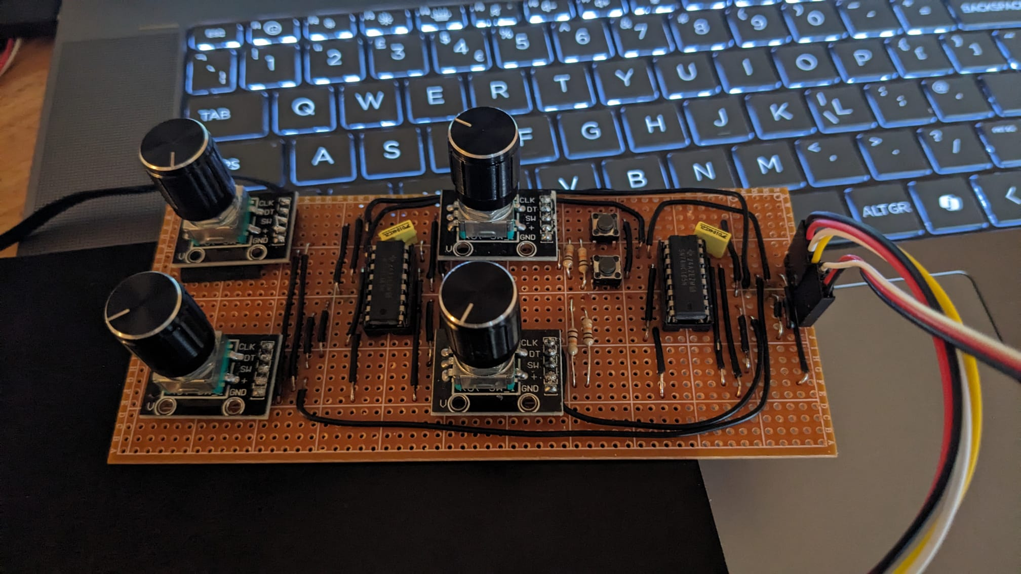
Here's my stripboard lash-up.
Attached are Claude's (almost) first attempts at a driver and test program, seems to work, buttons are fine but the encoders are a bit sensitive and seem to miss a few steps.
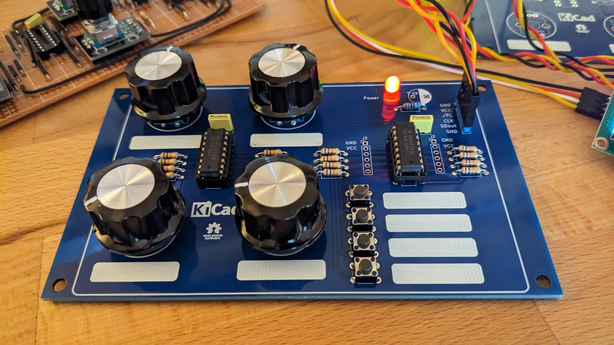
Now on a PCB, will try using Claude to improve/modify the driver and demo.
That looks very useful for instrument control / software radio experimentation. Four encoders would cut the menu 'hunting' quite a bit and make usage more pleasant. I remember HP once produced an oscilloscope with only buttons on the front panel. It was an awful user experience. Now scopes have long been back with a smattering of knobs and are much more intuitive again.
I wonder if the encoders are such that their screw collars would fit through a front panel, along with the 'power' led if extended on it's leads. The buttons would need some 3D printed extensions to be tall enough to do the same. The connector could be fitted with a right-angle so as not to not get in the way. Cheers, Bob
Thanks Bob! PCB is working OK with some Claude AI generated code. I'm hoping to improve the code by pushing as many features as possible into the driver, such as setting the initial values, value clamping (so encoder changes beyond limits are ignored) and then just reading the values directly from the HUB memory in the main application. I used some buttons and knobs that I had to hand but I couldn't find my right-angle header strip
If you want clean behavior you need to have your caller code clamp to your limits, and have the hub value called and updated by the PASM code. This topic came up when someone thought that I'd appreciate a, "Aha, JonnyMac! The AI found an error in your P2 encoder driver!" and went public without the courtesy of asking me about it first. It turns out that I knew the P2 better than the AI, and I would suggest that more than 75% of the programmers in these forums do, too. The problem was not in my driver, it was in the AI's limited knowledge of the P2, and practical, real-world programming with it.
This is what I do with my P1 drivers (P2 has encoders built into Smart Pins):
A) Read the new inputs
B) If no changes, back to A
C) For each channel
    -- if change in this channel
       * read current value from hub
       * update
       * write new value back to hub
It's simple, but sometimes missed: Instead of simply returning the clamped value to the caller, write it back to your Spin-level encoder array so that the update is used during the next detected change at the PASM level.
Also, as you're creating an HMI, you may notice that some encoders that have a nice mechanical "click" feel to them will jump by 4 encoder counts per click. This is easy to deal with, you just need to know about your encoder type when you call start(). When the d4x parameter is set to true, each "click" will result in a change of one count at the user level.
I've attached a small, 1-channel encoder drive that works as I've described here. I handle the button in the hub. In your case I'd suggest you just write the buttons byte to the hub to allow the top-level code to deal with them like inputs.
Thank you for your input Jon, very helpful.
Attached a ZIP of the Claude driver and demos.
BTW, f anyone is interested in the KiCAD project let me know and I'll share.
Cheers, Tony
I chained a couple of boards together and helped Claude AI with creating an 8 encoder / 16 button '165 serial driver object and demo.
Seems to work well. PCB needs an input header and switchable GND/ Serial_in for the first '165.