

Modulated Light Beacons for Orientation in a Room
 Christof Eb.
Posts: 1,542
Christof Eb.
Posts: 1,542
in Robotics
Hi perhaps someone has done something similar or has some other comments? - Thanks in advance!
Idea is:
- A robot is moving inside a room.
- Goal is to have position and orientation.
- It has a fototransistor mounted similar to the robots having a ping sensor, so that it can be turned horizontally with a servo motor. Actually the idea is to use the same servo. The fototransistor is sitting in a tube, so that it's angle of vision is limited. - A 1 pixel camera.
- In the room there are at least 2 light beacons, which each have a light (preferable visible). These lights are modulated as square wave blinking on/off but the two (or more) beacons each have their own frequency, to be able to distinguish them.
- The signal from the fototransistor is high pass filtered, amplified and fed to a P2 ADC then filtered again either with the Goertzel Smart Pin Mode or with Goertzel Software working on a sampled buffer.
I had done something in this direction using a camera some time ago. It's frame frequency was low and the blinking frequency was also low. Now I am more thinking of something like 10 kHz.
The method seems to be interesting, because a beacon can be build cheaply and the hardware on board of the robot seems also to be very simple, if the P2 can do a lot.
Of course wondering about resolution and possible range.
Cheers Christof
Comments
While not same as you are planning, at least it might give you some ideas: Earlier this year I used modulated IR for navigation in a straight line, see this discussion (you were also participating): https://forums.parallax.com/discussion/comment/1566360/#Comment_1566360
I got a lot of help from @JonnyMac so kudos to him.
Hmm... Maybe one would want to use a camera to localize the beacon? In that case would want to use very low frequency, <<60Hz...
Thank you! There are indeed some valuable hints in your thread!
Thanks! Yes, a camera is a possibility. I actually have done some experiments. https://forums.parallax.com/discussion/175897/thoughts-about-robot-navigation-using-blinking-beacons-and-camera-s#latest
In my opinion P2 is not really matching to cameras. Not enough RAM. Also I had problems controlling the camera when brightness was low. The camera then switched to a very slow frame rate.
Idea now is to use the onboard possibilities of the microcontroller with minimal external hardware.
Made a funny first measurement. Wanted to know if a LDR D=5mm might work here. LDRs are slow but I don't know how slow.
So I varied frequency and up to 500Hz it gives reasonable signal.
Sender is a bright yellow 5mm LED.
At a distance of 7cm I can see the 500Hz at some 3mV.rms in the FFT of my scope.
This seems to work better than my selfmade fototransistor which is a BC107 with a metal cap that was sawn off many years ago. :-)
Perhaps I should try a small solar cell as area seems to help?
Tried a solar cell 50x50mm. Frequency response is OK at 10kHz. Tried L=2.2mH, C=100nF and 1k in parallel to the Cell. If I pull out the C, there is no difference. (?) The 10kHz peak can just be seen at a distance of 25cm in the FFT of my scope, which also says Vpp=1.28mV. (Only!) Most of that is coming from one of my monitors.
Aha: Switched over from the yellow LED to an IR LED. Diode is driven via R300 at 3V3. ~7mA.
No changement at the receiver but now the peak is much clearer against noise and can still be seen at perhaps 1m. My desktop is getting too small . :-) The solar cell can obviously use the IR light very well. If I rotate the solar panel, the signal get's weaker, so the idea to pan the receiver seems possible.
It seems to start to make sense to build a selective preamp and to try real Goertzel. The hope is, that averaging over a longer time improves S/N ratio.
Yes, area always helps.
The common sensor for best performance on IR beans are PIN photo diodes, but these need sensitive amplifiers.
https://www.vishay.com/en/photo-detectors/
https://www.vishay.com/en/product/80492/
You could also look at IR receivers - these are simple, and use a modulated carrier for good light immunity and long range.
They come in different tweaks for code learning, data and remote control.
You could test what rotate speed can detect a burst, and when it sees two emitters, an OR signal would result.
A typical spin would then give - no signal - beacon A - beacon A+B - beacon B - no signal.
The centre of the skirt dropouts would be appx beacon angle, with some background lighting effects expected.
In smaller rooms, you may need to dial back the IR energy so reflections do not confuse the angles.
https://www.vishay.com/en/ir-receiver-modules/
The data ones say this
• Internal filter tuned to 38.4 kHz for 4800 bps or 57.6 kHz for 9600 bps
so 57.6kHz would allow shorter bursts of actual beacon ID, (and maybe beacon power ?) which could be useful.
Thank you @jmg for your inputs!
My parts boxes contain some IR receiver modules. It is tempting to try those, as their sensivity is great. They have this AGC, which can make things a bit tricky. If they get too much signal, they reduce their sensivity.
I once had a data transfer using such receiver. When the bytes contained too much bits set, data was corrupted .
I tried to find a discrete receiver schematic. Found something, which comes close but has very low sensivity:
https://www.elektormagazine.de/news/kleine-schaltungen-magischer-schlussel-folge-24
As I don't have too many inductors lying here, I tried to design a simple load for the solar cell with low impedance for DC and 50Hz but high impedance for 10kHz.
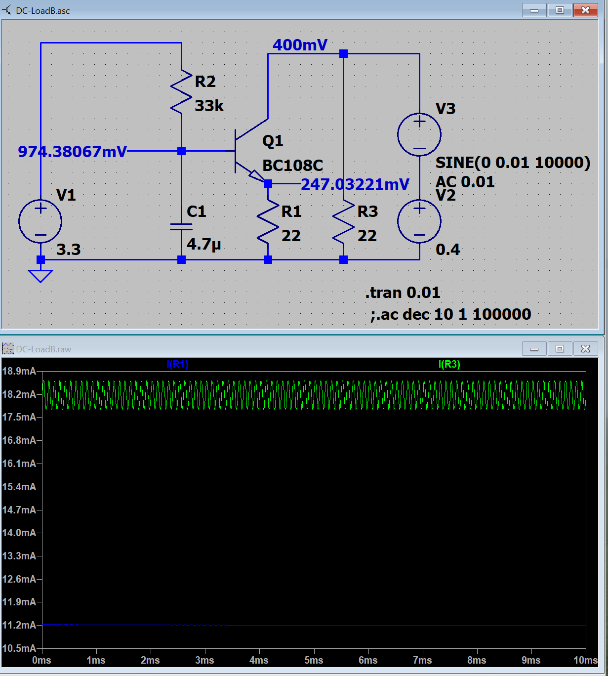
I had to free a breadboard and happened to find a LM386N-1 on it. - So Why not try this? It's 4-12V, be humble and swallow 3V3.
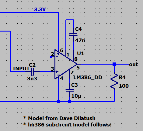
At 1m distance I get -44dBV at 10kHz from the solar panel with 1k load.
You get the best bandwidth/cost from a receiver like this:
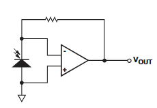
Use a PIN photodiode and a high speed opamp. The diode is effectively shorted so the photo current doesn't have to charge the capacitance and there is very little RC delay. The opamp is wired as current controlled voltage source and amplifies the signal so that the current through the resistor matches the photo current.
I'd suggest a radar-like setup. Let the receiver spin constantly like a radar antenna. If it rotates at, say 10Hz = 600RPM and the modulation frequency is something around 100kHz you have 10,000 periods per 360° and can expect an angular resolution of ~1000/rev or ~0.4°.
To avoid having to use slip rings for the diode you could build an "inverse Kojak light": place the receiver diode vertically in the center axis. Rotate a lens and a 45° oriented mirror on top of it. A magnetic encoder can be used to get the absolute angle in real time.
Hm, needed a while to grasp this. High pass filtering would be done in a second stage. Can't think of a version with integrated high pass. Problem is, that DC and 50Hz from lamps are very much more power than the IR sender. For my solar cell, I would need a TDA2030?")
Thank you! I am learning a lot here.
At the moment sun is shining into the room, but not really onto the solar cell. It gives 0.33V DC at 1k load.
Signal Strength after Amplification x200 per LM386 over distance. IR current about 5mA 10kHz Square Wave. 1.6V*5mA= 8mW.
Solar Cell 50mmx50mm, 1k Load.
At about 1,7m distance, the signal in the FFT vanishes in the noise.
I had thought, that voltage should decrease with distance^-2 but it's only distance^1.6 . ???
EDIT: Decrease with distance^2 is the rule for power, so my finding about voltage is plausible, I think.
Unfortunately I don't know, what current I can apply to this IR sender diode. Most seem to bear >=50mA.
Perhaps I should try some white 3W LED 700mA, that I have?
Edit: tried the IR LED with ~30mA and got from 1mV.RMS to 5mV.RMS at 1.7m distance.
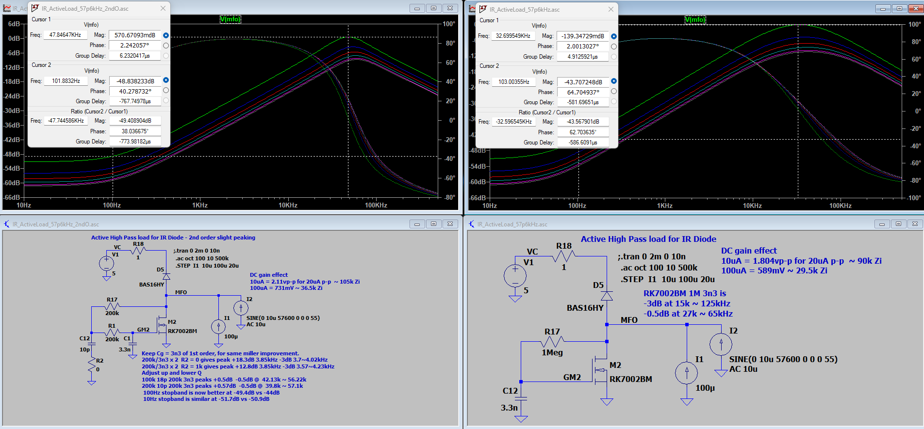
Yes, often an active load is used for the photodiode, that can provide 'static' DC~100Hz bias, but that gives a high impedance at IR frequencies.
Here is an example, where I1 is sunlight and lamps, and I2 is the wanted signal.
Addit : Plot updated to 2 choices, 2nd order feedback and tweak for slight improvements. Better 100Hz~1kHz rejection
interesting discussion on frequency detection of optical signals... But, let me throw in what came to mind when reading the post subject, as I, too, have been scheming a dead simple system for distinguishing frequencies using cheap (cadmium di-sulfide?) photo-resistive cells. I found myself up in the frequencies of visible color light... and using the difference in the values of light coming through colored filters - green and yellow, in particular, to distinguish live/dead grass. I had very promising results just taping together a little handheld rig with two photocells and filters side by side and cheap analog volt meters on each... the needle swing was remarkably (that's why I'm remarking on it") ) pronounced and encourages me to keep on that approach when I dig the project out again and the grass appears in the northern hemisphere.
) pronounced and encourages me to keep on that approach when I dig the project out again and the grass appears in the northern hemisphere.
So, if colored light in the corners is an option you might consider something like that... imagine 4 photocells behind 4 primary color filters at the back of a 10? cm black plastic tube (black tube, as well as length and narrowness, aid directional precision) . This 4 filter scheme is one I use in a custom Non-Dispersive Infra-Red (NDIR) engine exhaust gas detector (2 gasses, 1 H2O, one reference). Anyway, lots of NDIR algo resources with that scheme, if you need.
use the same color filter plastic over the light sources themselves probably increases distinction.
actually, that grass detection scheme I was aiming to build out entirely analog... no micro at all, potentially.
How about this?
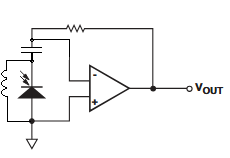
The capacitor couples the HF component of the signal to the opamp input while the inductor shorts the DC component.
Direct sunlight has to be shielded and filtered optically. There is no way you can supress that electrically since the intensity is many orders of magnitude higher.
Hi,
")
I love your input very much. One of the most simple and at the same time powerful methods to find objects with a camera is to give them a color, that is nowhere else in the picture.
Thank you, this is very interesting!
Christof
Hi everybody!
As I am no electronics engineer, I often do not know the right words to google, so perhaps someone can help me here:
This is very similar to radio transmission.
I have a weak signal in a sea of DC and noise. I would like to know some rules or equations to describe the possibility to discern this signal from the noise.
I do have relatively good knowledge about statistics to gain results from tests.
I assume, that if you measure for a longer time taking the average that you can "see" a weaker signal.
(Unfortunately my oscilloscope does not allow to average a number of FFTs, it is only possible to average the signal itself, which only helps, if you can trigger.)
There must be some rule about the S/N ratio of the carrier (10kHz here) and the bandwidth of the transmitted information? I even don't know how the level of noise is defined.
Cheers and thanks in advance, Christof
Yes, that can work.
In practice it has limitations
One plus, it is is very frequency tolerant of DC currents.
If you compare the plots above, there is slight change in GM and peaks with DC/LF shunt current, as the shunt fet moves its operating point slightly.
here is a frequency and time domain plot, showing the ringing effect of moderate Q, needed for data modulate.
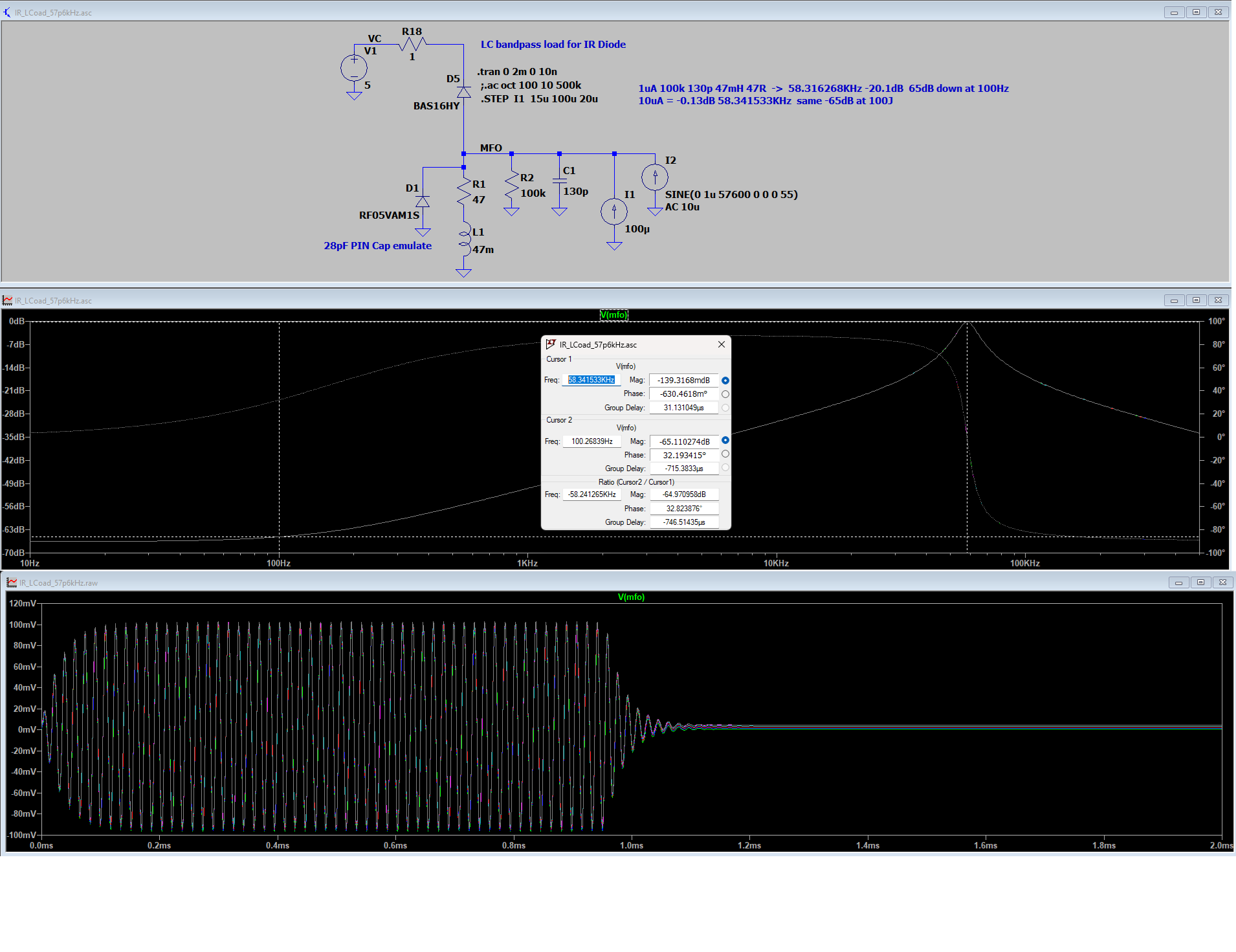
Yes, there is a trade off.
You can pick a very high Q, and get very good noise rejection. (you need to ensure the resonant freq equals your transmit freq)
The trade off is, high Q means more ringing, and slower decays so modulation speed has to be slower.
The plot above has that in picture form. You can see the frequency domain peak, and the time domain slow decay that results.
There were high Q tuning fork resonators used for tone call radios, FWIR 500Hz-2kHz with 100's ms ringing times. They would trigger on tones well into the noise.
I actually had these problems: The inductor did indeed pick up "something". And the inductor 2.2mH, (that I happened to have and that looks as if it could cope with the solars cell's DC current) did not yield enough impedance at 10kHz.
At the moment my feeling is, that my setup with that solar cell "should work", as I can push up sending power. If it was able to receive 8mW at 1,7m, then I would need (15m/1,7m)^1.6*8mW= 260mW. (??)
Thanks for the input. If I define V.RMS when the sender is off as the "noise level" = 13mV, then a level of 5mV.rms after FFT is also "well into the noise".
I use a microcontroller to generate the sender frequency. (What a waste) So the sender frequencies are very well known.
(Seems also, that I could learn a lot about LTSpice from you....)
I will now have to focus onto ADC-sampling and do Goertzel software filter + averaging.
Cheers and thank you!
Christof
So now got adc sampling and software Goertzel filter for single frequency 10kHz running.
For now:
Sampling at 31250Hz, buffer length 500, => sampling of 20 buffers takes 320ms
A triangle window and software Goertzel applied to each buffer, then average over the 20 buffers.
Sample + window + analyse together takes 450ms
Numbers are dB of magnitude.
The picture shows at about 57dB the received signal and at 45dB the signal when the line of view to the sender is cut.
Signal is from IR diode on/off 30mA at 1,7m distance. Room is mainly lit by my monitors.
Reducing to 10 buffers and thereby reducing time to 225ms looks like this:
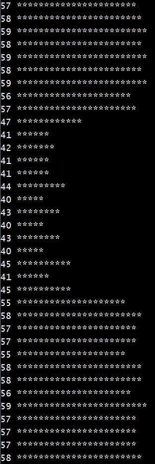
When I switch off one of my monitors the picture looks like this for 20 buffers:
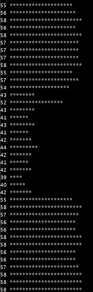
I think it is not the light from the monitor but something transmitted via Aether.
So all in all the method to receive a 10kHz IR signal with 50mW at 1,7m distance works but needs ~0,5sec for one magnitude.
Here is a further variant, with an OTA load, which presents a low impedance to the photo device, so makes the Sensor Cp have less effect.
A higher IR carrier is chosen to allow easy swap/compare of a custom design with the faster all-as-one Vishay parts, and to give highest 10-100Hz rejection
Compared with #14, the variation with gain & peak with dc injection is reduced. The f(peak) is tuned for least change with DC-I
.asc renamed to attach