

Thoughts about Robot Navigation using Blinking Beacons and Camera(s)?
 Christof Eb.
Posts: 1,597
Christof Eb.
Posts: 1,597
So I am still pondering about cheap but precise navigation of a little robot. (Target lawn mower) I want to have the position with repeatability of +/- 3cm within a field of about 30m x 15m. The robot is allowed to stop or to do special movements to find it's position. Several beacons might be used.
As cameras are relatively cheap and have high resolution, the idea is to use beacon light(s) in combination with a compass and odometer. To distinguish beacons from other coloured pixels or from each other, the beacon shall blink with a known frequency or pattern.
To detect the blinking light in a picture, it will be necessary to first filter for the color of the beacon and then compare pictures. At the moment I think, that as result you only need an angle parallel to the horizon, not the information of height. So perhaps the picture can be reduced from 2 to 1 dimensions, which would be an enabler to use P2 without external RAM?
An OV7670 camera seems to have a picture angle of 25° with a resolution of 640x480 pixels. https://www.openhacks.com/uploadsproductos/ov7670_cmos_camera_module_revc_ds.pdf
So if we could find the light with a resolution of 100 lines, we would have 0.25°, which is equivalent of 2,1cm at a distance of 5m.
Comments? Ideas?
Have Fun! Christof
P.S. Perhaps I should mention, that I have seen, that sometimes some pattern recognition is used to find position. But I think, that it should be way more easy to find the position of a blinking light...
Comments
Finding the exact center of the light could be hard. For robustness, I think it would be best to search for the known blink frequency before finding the position of the beacon. Which would require a bunch of images to be stored in ram. To save ram, just crop a small region of the image and store several of those in hub ram. If height is known from previous measurements then only little strips would need to be stored.
If the blinking rate was very fast, and shutter speed was also very fast, then the blink would be on and off in adjacent lines. That assumes a rolling shutter on the camera and a shutter speed of ~1/15000.
The wavelength of an 88MHz signal is 3.41m. If the phase of such signal could be measured to within 1 degree, that is 9.4mm accuracy. There are several possibilities to resolve the ambiguity between wave crests. The system could switch to another frequency so the crests would not line up the same within the mowing area. It could do dead reckoning. Perhaps careful design of the transmitter array could eliminate ambiguity. All of the signals transmitted (only one active at a time) could be generated by a P2.
Ultrawideband radios are also great for positioning.
Thanks, James for Your comments!
Unfortunately my knowledge about radio is quite limited, so I should better not mess with senders. Why did you mention 88MHz of all things? ((As far as I know this is in Germany reserved for police and other public security....))
I think, I begin to understand the advantage of this very fast blinking idea. So you can look for a pattern in one picture. Very interesting!
Christof
Some other idea is not to use on-off blinking but to rotate Red Green Blue as hue value. This has the advantage that there is a signal at any time in the picture and that you would not need synchronisation between sender and receiver.
Take the base picture, convert to HSV, rotate the hue values of all pixels and store the picture. https://upload.wikimedia.org/wikipedia/commons/thumb/9/90/Colors-i54-ring.png/330px-Colors-i54-ring.png then take a second picture at the fitting moment and filter for the rotated colours. (Multiply saturations for each pixel of same hue.) Speed of rotation must be known.
To find the center in x-direction of a blob of known colour (hue) is quite simple in HSV room. It is just a saturation-weighted average of all x-values of pixels of that hue (or some range). https://en.wikipedia.org/wiki/HSL_and_HSV
The base picture must be in RAM, the second picture could be analysed on the fly, if processor speed allows it.
Perhaps PWM to mix colours at the beacon must be taken into account?
The idea would be, that completely changing colour, hue by 180 degrees, seems less likely in a picture than variation of intensity of a single colour. You could also do the multiplication step several times.
Christof
88-108 MHz is the FM broadcast band is most countries. https://en.wikipedia.org/wiki/List_of_FM_radio_stations_in_Germany
In USA it is legal to transmit a low power signal on these frequencies, provided it does not interfere with licensed stations. The P2 can transmit these frequencies directly with a simple low-pass filter. Higher frequencies will be above sysclock/2 and will need a band-pass filter for clean emissions. https://en.wikipedia.org/wiki/Undersampling (This article talks about receiving, but the same applies to transmitting.) FM broadcast receivers are cheap. To do the radio positioning we probably need raw IQ samples. Most FM receiver chips would not provide this. The cheap rtl-sdr would.
Hopefully the LED / CFL bulbs around would not flicker at similar frequencies as the beacons. And hopefully the flashing beacons don't trigger the camera's 50Hz flicker detection.
The color changing strobe is an interesting idea. An optimization to keep in mind is that a majority of camera, including the one you linked, can output data in YUV format. If the strobe alternated between red and green that would mostly only affect the V values. If the strobe alternated between green and blue that would mostly only affect the U values.
You might be able to implement a differential antenna approach. For instance we have a cottage that looks over Lake Michigan 140 feet above the water, but from the shore you cant see the cottage. We wanted to determine the approximate property line at the shore line.
So up at the cottage I setup TWO transmitter beacons at the edge of the property line (about 200 feet across from one another) .... each transmitter sent a continuous signal that was slightly different from the other centered around 1100kHz ... i.e. 1,100,500Hz and 1,099,500Hz.
Using an AM radio. (mine had digital tuning), individually you could not hear anything at 1100kHz from any one transmitter, but between the two transmitters you can her the beat frequency of 1kHz where it is loudest at the center between the two transmitters.
Thanks again for Your inputs!
I have started to try to make a driver for ov7670FIFO, which I had, for Taqoz. Lots of registers!!! Lots to learn.
The idea is now to use a blinking blue beacon LED and to apply Goertzel algorithm to each pixel of a series of pictures or rather only their blue part.
OK, several days later, I have finally achieved some sort of proof of concept.
Findings:
Down side:
So lets come to the up side:
The scene:
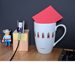
The grey scale picture:
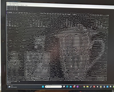
The filtered picture with a green X at the calculated position:
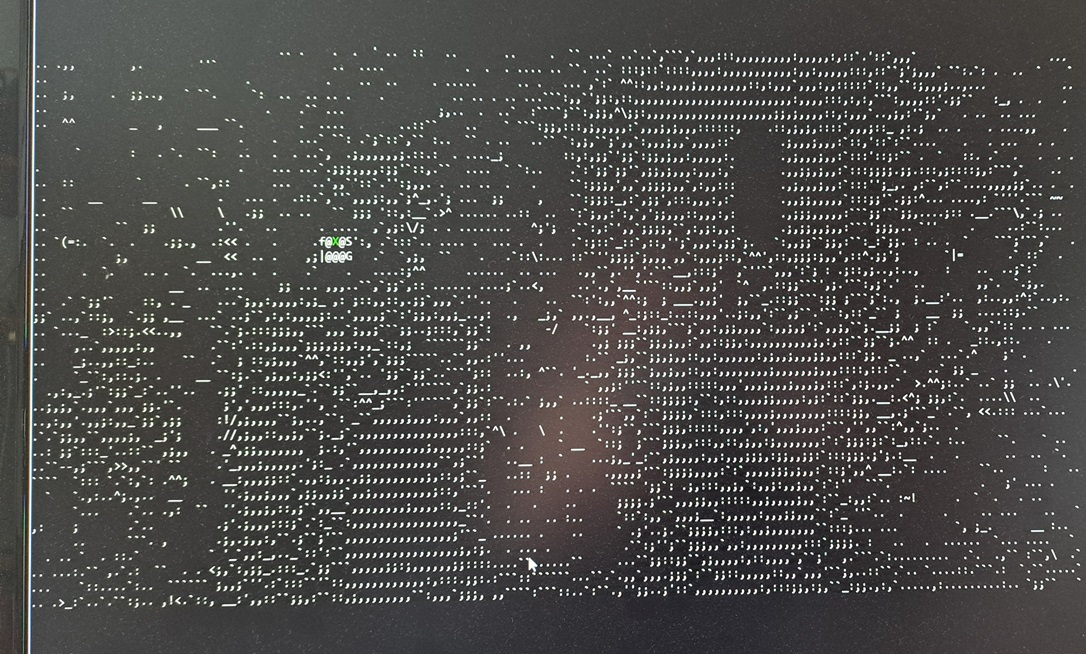
Cheers Christof
P.S.: A lot of my problems with this camera seem to come from some struggle between exposure time vs pixel clock frequency, defined by CLKRC. If I use $01, then I get nothing useful, if I use $05 then I get bad stripes at the lower part of the picture, if I use $07, then there is a bad region in the upper part of the picture. If I darken the room with $07, then the invalid regions grow to both upper and lower part.
Perhaps someone can tell me some magic hints?
Using 2* and 4* frame time for blinking cycle time of two beacons enables parallel detection of these 2 beacons after 8 frames in 42 seconds. 4 frames only lead to wrong positions.
Assembler programming might be able to bring the time down to perhaps 30secs.
Invested some more hours to bring down acquisition time, but unsuccessful.