

I uploaded some of my code to Claude and WOW!
 ke4pjw
Posts: 1,334
ke4pjw
Posts: 1,334
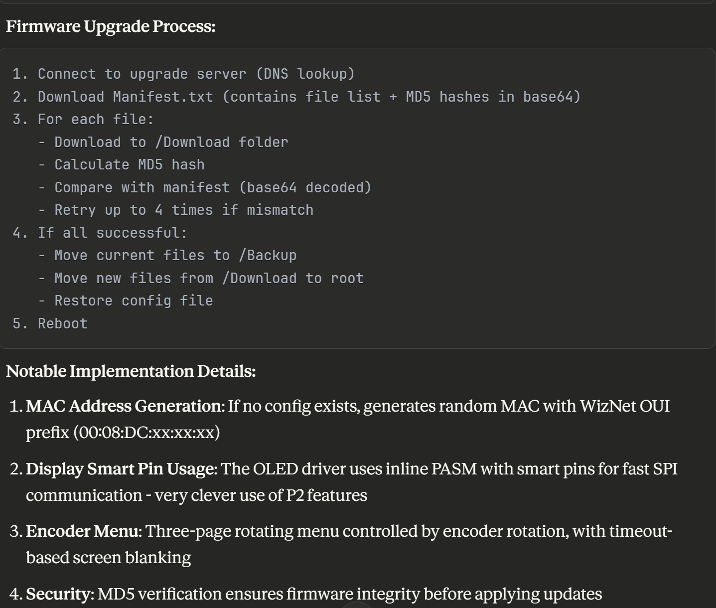
It's understanding of my firmware upgrade process is mostly correct. (The MD5 hash is actually a part of the header returned by Azure Blob Storage, not in the Manifest file.)
Comments
I am impressed with Claude too!
Playing with a TM1637 module (4-digit 7-segment display) from AliExpress, I tried a TM1637 demo and driver I found on the forum from Mr JonnyMac, (massive thanks to Jon for sharing so much, it's really appreciated) but that didn't work for me, after checking all the pin assignments, wiring, voltages etc., I 'scoped the data line and it looked like it was struggling to charge the line fast enough.
I asked Claude for a 'slow TM1637 driver' - it gave me the attached which worked first time, (I have since reduced the DELAY_US = 100 'Microseconds delay for bit timing - investigating the issue with my setup/code).
Cheers.
Tony
Bollington UK
Did you determine why my driver didn't work for you? I ask because I don't publish stuff that isn't working for me, and that driver was used in a prop for the TV show "For All Mankind." I recently ended up with more of those modules, so I'd like to see how your version differs from mine. Can you post your/Claude's version?
Tony might be fake. Possibly triggered by subject title.
I haven't had time to investigate my set-up any further, here's the Claude driver:
'' TM1637 4-Digit LED Display - Simple Driver Object
'' Usage: tm.Start(clk_pin, dio_pin, brightness)
'' tm.Display(1234, 4)
'' Claude 25 November 2025
CON
DELAY_US = 10 'Microseconds delay for bit timing
VAR
long clk_pin
long dio_pin
long clk_freq
PUB Start(clk, dio, brightness)
'' Initialize the TM1637 display
'' clk: CLK pin number
'' dio: DIO pin number
'' brightness: 0 (dim) to 7 (bright)
clk_pin := clk
dio_pin := dio
clk_freq := clkfreq
dira[clk_pin] := 1
dira[dio_pin] := 1
outa[clk_pin] := 1
outa[dio_pin] := 1
waitcnt(clkfreq/10 + cnt)
SetBrightness(brightness)
PUB Display(num, digits)
'' Display a number from 0 to 9999
'' num: number to display
'' digits: number of digits to show (1-4)
  if num < 0
    num := 0
  if num > 9999
    num := 9999
if digits < 1
digits := 1
if digits > 4
digits := 4
'Clear all digits first if showing fewer than 4
if digits < 4
Clear
'Display from right to left based on digit count
if digits => 1
WriteDigit(3, DigitToSegment(num // 10))
if digits => 2
WriteDigit(2, DigitToSegment((num / 10) // 10))
if digits => 3
WriteDigit(1, DigitToSegment((num / 100) // 10))
if digits => 4
WriteDigit(0, DigitToSegment(num / 1000))
PUB Clear
'' Clear the display
WriteDigit(0, 0)
WriteDigit(1, 0)
WriteDigit(2, 0)
WriteDigit(3, 0)
PUB SetBrightness(level)
'' Set display brightness
'' level: 0 (dim) to 7 (bright)
StartCondition
WriteByte($88 + (level & $07))
StopCondition
PRI WriteDigit(position, segments)
StartCondition
WriteByte($40)
StopCondition
StartCondition
WriteByte($C0 + position)
WriteByte(segments)
StopCondition
PRI DigitToSegment(digit) : segments
case digit
0: segments := %00111111
1: segments := %00000110
2: segments := %01011011
3: segments := %01001111
4: segments := %01100110
5: segments := %01101101
6: segments := %01111101
7: segments := %00000111
8: segments := %01111111
9: segments := %01101111
other: segments := 0
PRI StartCondition
outa[dio_pin] := 1
outa[clk_pin] := 1
DelayUs(DELAY_US)
outa[dio_pin] := 0
DelayUs(DELAY_US)
outa[clk_pin] := 0
DelayUs(DELAY_US)
PRI StopCondition
outa[clk_pin] := 0
outa[dio_pin] := 0
DelayUs(DELAY_US)
outa[clk_pin] := 1
DelayUs(DELAY_US)
outa[dio_pin] := 1
DelayUs(DELAY_US)
PRI WriteByte(value) | i, bit
repeat i from 0 to 7
outa[clk_pin] := 0
DelayUs(DELAY_US)
outa[clk_pin] := 0
dira[dio_pin] := 0
DelayUs(DELAY_US)
outa[clk_pin] := 1
DelayUs(DELAY_US)
outa[clk_pin] := 0
dira[dio_pin] := 1
DelayUs(DELAY_US)
PRI DelayUs(microseconds) | clocks
clocks := (clk_freq / 1_000_000) * microseconds
waitcnt(clocks + cnt)
Cheers.
Tony
Must be a hardware issue with my bench lash-up - display power is +5V, i'm driving the clk and data directly from P1. Attached 'scope traces of the the data line, haven't had time to investigate my set-up much further. Here's the Claude driver.
'' TM1637 4-Digit LED Display - Simple Driver Object
'' Usage: tm.Start(clk_pin, dio_pin, brightness)
'' tm.Display(1234, 4)
'' Claude 25 November 2025
CON
DELAY_US = 10 'Microseconds delay for bit timing
VAR
long clk_pin
long dio_pin
long clk_freq
PUB Start(clk, dio, brightness)
'' Initialize the TM1637 display
'' clk: CLK pin number
'' dio: DIO pin number
'' brightness: 0 (dim) to 7 (bright)
clk_pin := clk
dio_pin := dio
clk_freq := clkfreq
dira[clk_pin] := 1
dira[dio_pin] := 1
outa[clk_pin] := 1
outa[dio_pin] := 1
waitcnt(clkfreq/10 + cnt)
SetBrightness(brightness)
PUB Display(num, digits)
'' Display a number from 0 to 9999
'' num: number to display
'' digits: number of digits to show (1-4)
if num < 0
num := 0
if num > 9999
num := 9999
if digits < 1
digits := 1
if digits > 4
digits := 4
'Clear all digits first if showing fewer than 4
if digits < 4
Clear
'Display from right to left based on digit count
if digits => 1
WriteDigit(3, DigitToSegment(num // 10))
if digits => 2
WriteDigit(2, DigitToSegment((num / 10) // 10))
if digits => 3
WriteDigit(1, DigitToSegment((num / 100) // 10))
if digits => 4
WriteDigit(0, DigitToSegment(num / 1000))
PUB Clear
'' Clear the display
WriteDigit(0, 0)
WriteDigit(1, 0)
WriteDigit(2, 0)
WriteDigit(3, 0)
PUB SetBrightness(level)
'' Set display brightness
'' level: 0 (dim) to 7 (bright)
StartCondition
WriteByte($88 + (level & $07))
StopCondition
PRI WriteDigit(position, segments)
StartCondition
WriteByte($40)
StopCondition
StartCondition
WriteByte($C0 + position)
WriteByte(segments)
StopCondition
PRI DigitToSegment(digit) : segments
case digit
0: segments := %00111111
1: segments := %00000110
2: segments := %01011011
3: segments := %01001111
4: segments := %01100110
5: segments := %01101101
6: segments := %01111101
7: segments := %00000111
8: segments := %01111111
9: segments := %01101111
other: segments := 0
PRI StartCondition
outa[dio_pin] := 1
outa[clk_pin] := 1
DelayUs(DELAY_US)
outa[dio_pin] := 0
DelayUs(DELAY_US)
outa[clk_pin] := 0
DelayUs(DELAY_US)
PRI StopCondition
outa[clk_pin] := 0
outa[dio_pin] := 0
DelayUs(DELAY_US)
outa[clk_pin] := 1
DelayUs(DELAY_US)
outa[dio_pin] := 1
DelayUs(DELAY_US)
PRI WriteByte(value) | i, bit
repeat i from 0 to 7
outa[clk_pin] := 0
DelayUs(DELAY_US)
outa[clk_pin] := 0
dira[dio_pin] := 0
DelayUs(DELAY_US)
outa[clk_pin] := 1
DelayUs(DELAY_US)
outa[clk_pin] := 0
dira[dio_pin] := 1
DelayUs(DELAY_US)
PRI DelayUs(microseconds) | clocks
clocks := (clk_freq / 1_000_000) * microseconds
waitcnt(clocks + cnt)
Cheers.
Tony
Please attach your code as a file. Simple copy-and-paste into the thread destroys important formatting. Thanks.
Just a note. AI "helpers" don't understand the full nature of the Propeller, so they produce code that is expected to be compiled. This isn't something I do with the P1 because I need all the code space I can get; critically-timed code ends up in a cog. For example, When I toggle a pin with your DelayUs() method and run in with the interpreter, what is supposed to be 10us turns into 58us. This doesn't cause any harm in this application, but in other situations it could.
If the code is run through FlexProp the clock time is about 13us -- certainly closer to what Claude wanted to have.
I do in fact use Claude from time-to-time, but never to develop full code; I ask for something generic and then tune it to the P1 or P2. Recently I needed a SHA256 hash object for the P2 and used Claude, some prompt tuning, and some manual editing to get an object that works like the P1 code that I inherited from another programmer.
Thanks for the tip to attach code, and the informative note on AI understanding. My Claude TM1637 driver is since modified to display HEX, I only have this latest version (attached). If DELAY_US constant is reduced below 5, the TM16387 does not seem to start-up. Tested with 2 x modules, blue LEDs, labelled "DIY MORE".
Cheers, Tony
You have yet to attach code to a post....
Thanks for the tip to attach code, and the informative note Jon.
My Claude TM1637 driver is since modified to display HEX, I only have this latest version. If DELAY_US constant is reduced below 5, the TM16387 does not seem to start-up. Tested with 2 x modules, blue LEDs, labelled "DIY MORE".
Attchment is not 'sticking' for some reason, I'm OOO at the moment, will try again soon.
Cheers, Tony
File uploads are limited by types. ZIP your project and attach that -- it will give those who want to look all the files they need (it's bad form to assume everyone has all the same files you do).
Thanks Jon, ZIP now attached. Also playing with a Claude driver for MAX7219 8-digit module if anyone is interested.
Thanks Jon, ZIP now attached. Also playing with a Claude driver for MAX7219 8-digit module if anyone is interested.
"You are not allowed to upload files in this category"
Seems to work for me. I just dragged and dropped the zip.
Drag and Drop appear to be broken.
So is the upload option on the menu.

I think I just found the issue. Please try to post the attached file again.
Thanks Ari.
I will connect a display and try your code this weekend, but a couple things jump out -- I don't know if you're responsible or claude.ai is responsible; if the latter, depending on AI without question might be interfering in your opportunity to learn a language completely. For context, I write code for a laser tag company and in our current P1 product we're always looking for opportunities to shave time and code space.
This stuck out like a sore thumb:
if num < 0 num := 0 if num > 9999 num := 9999The code is fine, but is slower and uses more code space than if you take advantage of Spin features. You could start with a fix that doesn't check the second if statement when the first if statement is true
  if num < 0
    num := 0
  elseif num > 9999
    num := 9999
If num is less than zero there is no need to check if it's greater than 9999, so the elseif fixes things. Still, this clamping operation can be wrapped into a single line of code:
This does the same as the original four lines but it faster and lighter (by 10 bytes in Propeller Tool). I do time testing with this bit of P1 code.
At the end of this section t will hold the number of system ticks required to run the code. The 368 constant in the second timing line removes the overhead of those two lines. Here's the result of testing three versions: A is the original, B is with elseif, and C uses #> and <# in one line.
                 A       B       C
                ----    ----    ----
num < 0         1680    1136    1040
num in range    1392    1392    1040
num > 9999      1728    1728    1040
Your driver has two __ToSeg() methods, when you only need one. If you add a second parameter (desired base), you can use one method like this:
pri digit_to_segs(digit, base) : segments

  if (digit < 0) or (digit => base)
    return %00000000

  case digit
    $0 : segments := %00111111
    $1 : segments := %00000110
    $2 : segments := %01011011
    $3 : segments := %01001111
    $4 : segments := %01100110
    $5 : segments := %01101101
    $6 : segments := %01111101
    $7 : segments := %00000111
    $8 : segments := %01111111
    $9 : segments := %01101111
    $A : segments := %01110111
    $B : segments := %01111100
    $C : segments := %00111001
    $D : segments := %01011110
    $E : segments := %01111001
    $F : segments := %01110001
With this one method you can display binary (base 2), quarternary (base 4), octal (base 8), decimal (base 10), and hexadecimal (base 16) digits.
For contiguous values like this, though, I prefer to use a table.
dat

  SegMaps       byte    %00111111, %00000110, %01011011, %01001111
                byte    %01100110, %01101101, %01111101, %00000111
                byte    %01111111, %01101111, %01110111, %01111100
                byte    %00111001, %01011110, %01111001, %01110001


pri digit_to_segs(digit, base) : segments

  if (digit < 0) or (digit => base)
    return %00000000

  return SegMaps[digit]
I find the table gives me more flexibility, especially if I decide to display the limitied set of ASCII characters on a 7-segment display. BTW, the case version takes about 5168 ticks to return a segment map and the method using 142 bytes, while the table and associated method do the same task in 2928 and in total uses 32 bytes of code space.
In the end, you'll decide what works best for you. My suggestion is that AI -- in most cases -- be used for guidance, not finished code.
Thanks for your time Jon, and for all the SPIN objects you share, you are a star!
I checked my code last night -- going back to what I last posted in this thread.
-- https://forums.parallax.com/discussion/170945/tm1637-driver-spin
The code worked fine with an older display, but not with a recent purchase. It turns out that the TM1637 -- especially when used in open-collector/drain mode (per its design) -- is pretty slow (despite a basic web search claiming a clock speed of 250kHz). I noticed that an Arduino driver for the chip used a 100us delay for the half-bit timing. I tried this and it worked with the new display. I ran that code through FlexProp and it worked just fine.
In Propeller Tool, the clock rate is about 3.9kHz with my updated driver.
The same program compiled with FlexProp gives a clock about 4.8kHz.
I reran your demo and noted your clock rate -- using driven IO pins (that are supposed to be open-collector/drain) -- is about 5.5kHz
I will post my updated driver in the original thread.
Cheers Jon, I'll use it in my project - it will join a few other jm objects!