I'm wondering about the SoG and YPrPb thing. In SoG mode with NeoYume the sync is definitely working as I have a stable image. It appears that red and blue colour channels are present in the image where expected, but there's just no green channel video on screen, and what is meant to be white is coming out purple (red+blue), instead of red+blue+green. I still wonder if the levels are setup right or if this thing expects negative 0.3V on green for sync and the different P2 DAC offsets are messing it up. Perhaps the DC restoration during the horizontal blanking intervals is not doing the correct thing to setup the DC levels...? The ADC's are AC coupled on each channel so I would have thought they can work independently but who knows. It could also potentially require i2c access to fully enable SoG perhaps via registers, although I'd imagine it should be possible to detect automatically - and it's already dealing with the lack of sync on H&V on its own too.
I also probed the input impedance of the SOG pin when unpowered and its like 28 mega-ohms, same as each video input. I guess I could probe it with a scope to see if anything is pulling down the green signal on the ADC side while running..?
EDIT: Yeah, on the scope, the green input pin (GIN in schematic) is pulled down to zero voltage at the blanking level after the input coupling cap. So DC restoration is happening and the sync tips go negative. On blue and red channels at BIN, RIN, they actually rise by about 0.2V, same with the SOG pin, surprisingly.
Yeah it's definitely doing something weird. If we had the datasheet we'd know better.
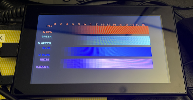
Here's the test that shows RGB levels increasing independently in SOG mode and what is displayed on the monitor. Red and Blue seem okay but green behaves like luminance Y.
Lighting here is bad for the photo but you can see red and blue channels are okay, in real life the green bar is actually a grey scale, and the white bar is actually magenta. Maybe YPbPr really does this although I thought Pb/Pr were colour differences not real red and blue. EDIT: actually they would be the difference if Y=0 when green is not present.
@Rayman said:
Maybe feed the full green signal to the sog pin? Just a thought. Maybe it’s looking there for video and sync…
I do actually feed green into SOG via a capacitor. I also wondered whether SOG was a logic level input that puts it into SOG mode and takes the data from GIN. GIN behaves differently to SOG as far as that DC restoration step.
I told you, it's trying to do YPbPr->RGB conversion. Just use YPbPr then. It's free. (In my driver SoG and YPbPr have the same code path, it's just the matrix settings that are different).
The reason you see the red/blue bars instead of the perhaps expected cyan-gray-red and yellow-gray-blue is because the Pb=Pr=0 white point is calibrated during blanking (that DC restoration circuit at work). Pb/Pr would blank at roughly mid level, so when it needs to it can go negative. R/B blank at zero, so they can never go negative. Also notice that the red/blue bars in your picture saturate at roughly the half way point.
@Wuerfel_21 said:
I told you, it's trying to do YPbPr->RGB conversion. Just use YPbPr then. It's free. (In my driver SoG and YPbPr have the same code path, it's just the matrix settings that are different).
We can certainly use component, I'm just trying to figure out what's actually wrong with SoG operation and why it's not working at all. This chip advertises having that capability with the SOG pin input and also automatically distinguishing between VGA and YPrPb (probably only possible via hsync/vsync/sog signals?). I may not be feeding in the signal in correctly, or its SOG pin might be a logic level input or its expecting a separately decoded external sync etc. In the block diagram the ADC is attached to the green channel which is doing DC restoration for sure unlike the other channels - although it would need to do that too for YPrPb. SOG seems to feed into the sync logic block only. If I remove this 1nF capacitor on my board feeding SOG I could try pulling it high or low via a resistor or feeding via another cap to the green input pin GIN directly perhaps to see if that does something else with the already clamped input level. I may try that today.
Much more likely: this is configured using that EEPROM business and the default is auto detect on sync type, because that way you can use the same bare chip for both VGA and YPbPr converter boxes. Consider the fact that sync-on-green basically does not exist as an output format in consumer electronics.
@Wuerfel_21 said:
Much more likely: this is configured using that EEPROM business and the default is auto detect on sync type, because that way you can use the same bare chip for both VGA and YPbPr converter boxes. Consider the fact that sync-on-green basically does not exist as an output format in consumer electronics.
It could also be via an i2c register, but then why even need the separate pin?
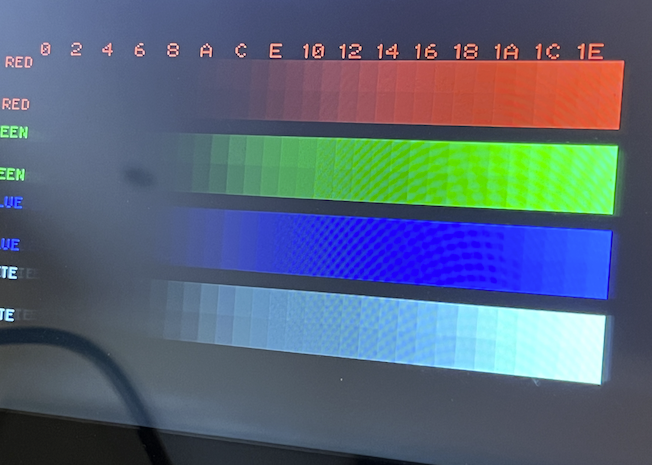
Yeah I think so. I just patched NeoVGA SOG to setup the colourspace converter like this and this was the result. It's a nicer ramp in real life, photo exposure makes it look too bright at lower ramp levels. This was also possible with true component in the past using just the Y signal IO pin IIRC for analog video setups.
A setup with a converter like this could allow HUB RAM based monochrome 1080p to an HDMI monitor with a ~254kB framebuffer (if that's useful - maybe for large signage apps etc). Over time as component & VGA options disappear even more something like this will become useful when you need high refresh rate HDMI or DVI output at resolutions higher than VGA. With external RAM we can get 1080p60 and 256 colours.
cmode_sync_on_green ' RGB SoG mode
long $00_00_00_00   ' DAC blanking value
long Y_BLANK        ' Blanking color
long Y_SYNC         ' HSync color
long Y_SYNC         ' VSync color
long Y_BLANK        ' HSync+VSync color
long 0              ' Color burst color (NTSC/PAL only)
long 0              ' Color burst frequency  (NTSC/PAL only)
'long $5A_00_00<<8 + BLANK_LEVEL   ' CY
'long $00_5A_00<<8 + BLANK_LEVEL   ' CI
'long $00_00_5A<<8 + BLANK_LEVEL   ' CQ
long $00_00_00<<8 + BLANK_LEVEL   ' CY
long $00_5A_00<<8 + BLANK_LEVEL   ' CI
long $00_00_00<<8 + BLANK_LEVEL   ' CQ
long 0              ' CQ XOR value (NTSC/PAL only)
@Wuerfel_21 said:
The reason you see the red/blue bars instead of the perhaps expected cyan-gray-red and yellow-gray-blue is because the Pb=Pr=0 white point is calibrated during blanking (that DC restoration circuit at work). Pb/Pr would blank at roughly mid level, so when it needs to it can go negative. R/B blank at zero, so they can never go negative. Also notice that the red/blue bars in your picture saturate at roughly the half way point.
You are right about the levels. When I generate real YPbPr in NeoVGA then the colour ramp is equal for R,G,B channels on the 240p tests. But if I choose SoG output in NeoVGA then the blue and red ramps are offset higher to begin with and saturate early. So it does appear that SoG is just mistaken for component in this device, and some other mechanism would be needed for true VGA SoG operation with 3 pins. Guessing it's in the register settings which potentially may be read in via an I2C EEPROM. My Simplecom CM201 has an empty I2C EEPROM location on the board for that (separate from the local EDID EEPROM to VGA), although that product uses a MS9288 not an MS9288A and may have a different pinout and/or functionality again.
Few other data points. If I ground either the GIN or SOG pins during operation then sync drops out and the picture disappears for NeoVGA's SoG and YPrPb modes. However in RGBHV modes, grounding SOG has no effect and grounding GIN just drops the green channel from the display but sync remains. Grounding blue or red just drops that colour channel from the display regardless of the mode. So the SOG pin seems to need to be wired for YPrPb operation as well as also having Y going to GIN - it's probably using the same circuitry to get at the sync on that channel.
There's also a Component2HDMI box, I think the Simplecom numbers are CM505 (the CM501 does reverse direction). Might be interesting to open one of those and see which chipset it uses, and if they still use MS9288, does it have an eeprom configuration.
Yeah component is probably going to be more useful to save pins. I was hoping/assuming the four pin RGBS operation would be possible with the MS9288a, but can't seem to get it to work and if VGA SoG isn't doable either then that only leaves YPrPb or RGBHV as usable input source types. I didn't route H&V separately on the FireAnt so on my FireAnt adapter board used to breakout USB-C to HDMI I'll need to use component now instead of VGA as the input source type when outputting HDMI. The HSYNC pin can then be left off from CC1/CC2, which is probably safer too. Thankfully I jumpered my existing board to allow this. That leaves YPrPb to use the 4 TX/RX diff pairs on USB-C and audio on SBUS1/SBUS2 in my home-grown alternate mode cable. If the signal goes to a VGA monitor I could either keep HSYNC present on CC1/CC2 for RGBS or just use real SoG which my VGA monitor supports, but HDMI would then be inactive while VGA is passed through - it'd become an either/or choice, not a simultaneous output as originally planned (no big deal).
@Rayman said:
Maybe there is some clever way to combine vsync and hsync on one pin and then separate them with diodes or something?
Possibly some sort of voltage detection circuit with different voltage levels sent might work. Bit of mucking about to generate it though especially if already being done by P2 HW in the case of HSYNC on bit 0 of the DAC group. Although maybe we could use the BITDAC mode for the sync pin output and raise/lower the output range when VSYNC happens? That might just need a dual comparator for extracting HSYNC & VSYNC states...?
@Rayman said:
Hmmm what if hsync and red were same pin?
Well then we could potentially do one sync signal on red and the other on green or something rather non-standard like that. If we mess with the colourspace offsets at vsync time it might let you do that I guess, although the video levels will wander about - ok if DC offset is being removed during blanking.
I do wonder in VGA/component output mode if the DAC bit 0 that drives HSYNC (or CSYNC) can be setup in bitDAC mode or if that is somehow seperate to the output path and won't see the SYNC signal. Being a separate pin the multi-level thing might be cleaner on the video signals. Guess I need to try it out.
@Wuerfel_21 said:
You know, there's a part to solve this conundrum, it's called a sync seperator
Yep. I already know about LM1881 and LMH1981 products. In fact I've used a LM1881 on a project a long time ago but that was with 15.625kHz composite video decoding teletext. Maybe VGA would still be usable with it somehow, not sure. The LMH1981 is also $27 on Digikey and likely far more complex/expensive than needed. There is also a cheaper LMH1980 which could possibly get sync off the green signal if required. Perhaps there are other chip options - haven't dug into it that much. Not really that fussed about all this either way.
Also I just tried one other test, driving Red and Blue signals with different offsets to Green with the colourspace converter. I'd kind of hoped that the MS9822A might distinguish between RGB SoG and YPrPb if the R&B signals are offset differently to G vs all idling at the same level during blanking. But it didn't seem to help and the white text is still coming out as purple.
Sounding pretty hopeless. Still VSYNC is wide and HSYNC is narrow. Maybe some RC filtering can separate them enough?
Maybe you've spent enough time on that though.
It's not too bad. Happy to stick with 5 pin VGA on the breakout board from P2-EVAL headers, although it might be good to dual purpose that with i2c via jumpers if you wanted component only (assuming we can get the data sheet for registers).
On the FireAnt I'm sending out RGBS over USB-C, (could do YPbPb) but the S can either be decoded at the other end of the USB-C cable via an optional LMH1980 that splits composite sync to H&V. I'll think I'll put the footprint for that chip down on the adapter board as there's plenty or room, and populate it if I feel like simultaneous VGA & HDMI output is the way to go (it probably is for simplicity). If not populated the H&V sync inputs to the MS9822A will just float and YPrPb will be assumed. May need solder jumpers in that path in case the sync separator actively generates some bogus sync pulses when it can't detect anything valid and that messes up the MS9822A. Some further experimentation will be needed.


Comments
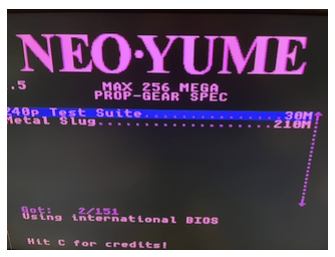
Interesting that font is readable, but the character sprites suffer from the classic "uneven eyes" syndrome.
I'm wondering about the SoG and YPrPb thing. In SoG mode with NeoYume the sync is definitely working as I have a stable image. It appears that red and blue colour channels are present in the image where expected, but there's just no green channel video on screen, and what is meant to be white is coming out purple (red+blue), instead of red+blue+green. I still wonder if the levels are setup right or if this thing expects negative 0.3V on green for sync and the different P2 DAC offsets are messing it up. Perhaps the DC restoration during the horizontal blanking intervals is not doing the correct thing to setup the DC levels...? The ADC's are AC coupled on each channel so I would have thought they can work independently but who knows. It could also potentially require i2c access to fully enable SoG perhaps via registers, although I'd imagine it should be possible to detect automatically - and it's already dealing with the lack of sync on H&V on its own too.
I also probed the input impedance of the SOG pin when unpowered and its like 28 mega-ohms, same as each video input. I guess I could probe it with a scope to see if anything is pulling down the green signal on the ADC side while running..?
EDIT: Yeah, on the scope, the green input pin (GIN in schematic) is pulled down to zero voltage at the blanking level after the input coupling cap. So DC restoration is happening and the sync tips go negative. On blue and red channels at BIN, RIN, they actually rise by about 0.2V, same with the SOG pin, surprisingly.
Maybe feed the full green signal to the sog pin? Just a thought. Maybe it’s looking there for video and sync…
Yeah it's definitely doing something weird. If we had the datasheet we'd know better.
Here's the test that shows RGB levels increasing independently in SOG mode and what is displayed on the monitor. Red and Blue seem okay but green behaves like luminance Y.
Lighting here is bad for the photo but you can see red and blue channels are okay, in real life the green bar is actually a grey scale, and the white bar is actually magenta. Maybe YPbPr really does this although I thought Pb/Pr were colour differences not real red and blue. EDIT: actually they would be the difference if Y=0 when green is not present.
I do actually feed green into SOG via a capacitor. I also wondered whether SOG was a logic level input that puts it into SOG mode and takes the data from GIN. GIN behaves differently to SOG as far as that DC restoration step.
Think Chip said he used AI on the datasheet and got something…
I told you, it's trying to do YPbPr->RGB conversion. Just use YPbPr then. It's free. (In my driver SoG and YPbPr have the same code path, it's just the matrix settings that are different).
The reason you see the red/blue bars instead of the perhaps expected cyan-gray-red and yellow-gray-blue is because the Pb=Pr=0 white point is calibrated during blanking (that DC restoration circuit at work). Pb/Pr would blank at roughly mid level, so when it needs to it can go negative. R/B blank at zero, so they can never go negative. Also notice that the red/blue bars in your picture saturate at roughly the half way point.
We can certainly use component, I'm just trying to figure out what's actually wrong with SoG operation and why it's not working at all. This chip advertises having that capability with the SOG pin input and also automatically distinguishing between VGA and YPrPb (probably only possible via hsync/vsync/sog signals?). I may not be feeding in the signal in correctly, or its SOG pin might be a logic level input or its expecting a separately decoded external sync etc. In the block diagram the ADC is attached to the green channel which is doing DC restoration for sure unlike the other channels - although it would need to do that too for YPrPb. SOG seems to feed into the sync logic block only. If I remove this 1nF capacitor on my board feeding SOG I could try pulling it high or low via a resistor or feeding via another cap to the green input pin GIN directly perhaps to see if that does something else with the already clamped input level. I may try that today.
Much more likely: this is configured using that EEPROM business and the default is auto detect on sync type, because that way you can use the same bare chip for both VGA and YPbPr converter boxes. Consider the fact that sync-on-green basically does not exist as an output format in consumer electronics.
It could also be via an i2c register, but then why even need the separate pin?
Can one do white on black with just one p2 pin?
Yeah I think so. I just patched NeoVGA SOG to setup the colourspace converter like this and this was the result. It's a nicer ramp in real life, photo exposure makes it look too bright at lower ramp levels. This was also possible with true component in the past using just the Y signal IO pin IIRC for analog video setups.
A setup with a converter like this could allow HUB RAM based monochrome 1080p to an HDMI monitor with a ~254kB framebuffer (if that's useful - maybe for large signage apps etc). Over time as component & VGA options disappear even more something like this will become useful when you need high refresh rate HDMI or DVI output at resolutions higher than VGA. With external RAM we can get 1080p60 and 256 colours.
That sounds great. I do have an old 1080p color text driver that might also be useful…
You are right about the levels. When I generate real YPbPr in NeoVGA then the colour ramp is equal for R,G,B channels on the 240p tests. But if I choose SoG output in NeoVGA then the blue and red ramps are offset higher to begin with and saturate early. So it does appear that SoG is just mistaken for component in this device, and some other mechanism would be needed for true VGA SoG operation with 3 pins. Guessing it's in the register settings which potentially may be read in via an I2C EEPROM. My Simplecom CM201 has an empty I2C EEPROM location on the board for that (separate from the local EDID EEPROM to VGA), although that product uses a MS9288 not an MS9288A and may have a different pinout and/or functionality again.
Few other data points. If I ground either the GIN or SOG pins during operation then sync drops out and the picture disappears for NeoVGA's SoG and YPrPb modes. However in RGBHV modes, grounding SOG has no effect and grounding GIN just drops the green channel from the display but sync remains. Grounding blue or red just drops that colour channel from the display regardless of the mode. So the SOG pin seems to need to be wired for YPrPb operation as well as also having Y going to GIN - it's probably using the same circuitry to get at the sync on that channel.
There's also a Component2HDMI box, I think the Simplecom numbers are CM505 (the CM501 does reverse direction). Might be interesting to open one of those and see which chipset it uses, and if they still use MS9288, does it have an eeprom configuration.
Yeah component is probably going to be more useful to save pins. I was hoping/assuming the four pin RGBS operation would be possible with the MS9288a, but can't seem to get it to work and if VGA SoG isn't doable either then that only leaves YPrPb or RGBHV as usable input source types. I didn't route H&V separately on the FireAnt so on my FireAnt adapter board used to breakout USB-C to HDMI I'll need to use component now instead of VGA as the input source type when outputting HDMI. The HSYNC pin can then be left off from CC1/CC2, which is probably safer too. Thankfully I jumpered my existing board to allow this. That leaves YPrPb to use the 4 TX/RX diff pairs on USB-C and audio on SBUS1/SBUS2 in my home-grown alternate mode cable. If the signal goes to a VGA monitor I could either keep HSYNC present on CC1/CC2 for RGBS or just use real SoG which my VGA monitor supports, but HDMI would then be inactive while VGA is passed through - it'd become an either/or choice, not a simultaneous output as originally planned (no big deal).
Maybe there is some clever way to combine vsync and hsync on one pin and then separate them with diodes or something?
Possibly some sort of voltage detection circuit with different voltage levels sent might work. Bit of mucking about to generate it though especially if already being done by P2 HW in the case of HSYNC on bit 0 of the DAC group. Although maybe we could use the BITDAC mode for the sync pin output and raise/lower the output range when VSYNC happens? That might just need a dual comparator for extracting HSYNC & VSYNC states...?
Hmmm what if hsync and red were same pin?
Well then we could potentially do one sync signal on red and the other on green or something rather non-standard like that. If we mess with the colourspace offsets at vsync time it might let you do that I guess, although the video levels will wander about - ok if DC offset is being removed during blanking.
I do wonder in VGA/component output mode if the DAC bit 0 that drives HSYNC (or CSYNC) can be setup in bitDAC mode or if that is somehow seperate to the output path and won't see the SYNC signal. Being a separate pin the multi-level thing might be cleaner on the video signals. Guess I need to try it out.
You know, there's a part to solve this conundrum, it's called a sync seperator
Yep. I already know about LM1881 and LMH1981 products. In fact I've used a LM1881 on a project a long time ago but that was with 15.625kHz composite video decoding teletext. Maybe VGA would still be usable with it somehow, not sure. The LMH1981 is also $27 on Digikey and likely far more complex/expensive than needed. There is also a cheaper LMH1980 which could possibly get sync off the green signal if required. Perhaps there are other chip options - haven't dug into it that much. Not really that fussed about all this either way.
Also I just tried one other test, driving Red and Blue signals with different offsets to Green with the colourspace converter. I'd kind of hoped that the MS9822A might distinguish between RGB SoG and YPrPb if the R&B signals are offset differently to G vs all idling at the same level during blanking. But it didn't seem to help and the white text is still coming out as purple.
Sounding pretty hopeless. Still VSYNC is wide and HSYNC is narrow. Maybe some RC filtering can separate them enough?
Maybe you've spent enough time on that though.
Regular 5-pin VGA sounds like the way to go.
It's not too bad. Happy to stick with 5 pin VGA on the breakout board from P2-EVAL headers, although it might be good to dual purpose that with i2c via jumpers if you wanted component only (assuming we can get the data sheet for registers).
On the FireAnt I'm sending out RGBS over USB-C, (could do YPbPb) but the S can either be decoded at the other end of the USB-C cable via an optional LMH1980 that splits composite sync to H&V. I'll think I'll put the footprint for that chip down on the adapter board as there's plenty or room, and populate it if I feel like simultaneous VGA & HDMI output is the way to go (it probably is for simplicity). If not populated the H&V sync inputs to the MS9822A will just float and YPrPb will be assumed. May need solder jumpers in that path in case the sync separator actively generates some bogus sync pulses when it can't detect anything valid and that messes up the MS9822A. Some further experimentation will be needed.