Converting component/VGA & audio to HDMI on P2
 rogloh
Posts: 6,312
rogloh
Posts: 6,312
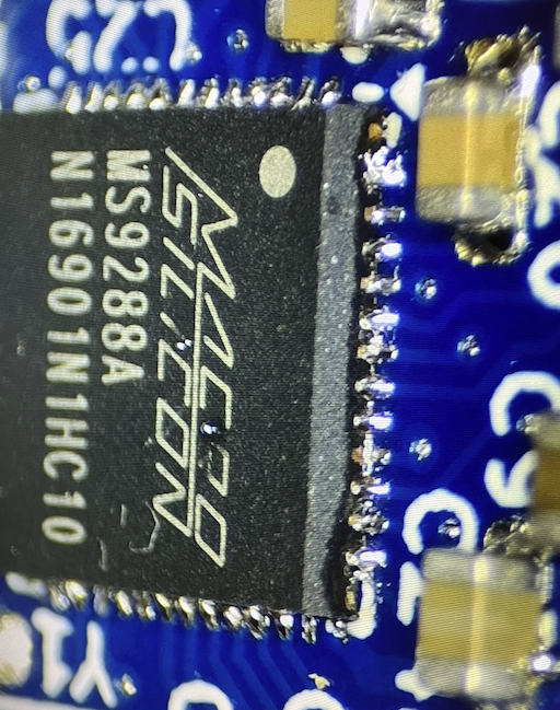
@cgracey I heard from @Tubular that there was some discussion today in the live forum about doing a component to HDMI board using a MacroSilicon product. It turns out that I've recently worked on exactly this. It was buried in the Logicon thread a couple of pages back from now but I have used a MacroSilicon chip to do the conversion and created a 40x20mm sized P2 breakout board that converts from VGA or component to HDMI (with audio). I now have this board working with audio, and here are some more details.
The MS9288A chip datasheet was unavailable online so I first used a Simplecom CM201 to figure out the general connection requirements and also later discovered more information online linked below regarding the connections to the device. I then created a schematic from following all of that and constructed a breakout board using it. The CM201 had a position for an EDID chip which has not been included due to pin limits of the 8 bit breakout, although if you used component video or SoG or Composite Sync it would free 2 more pins which could be used for I2C. IMO it would ideally read this information from the attached device not just from a local EDID chip.
https://github.com/Nold360/LibreHDMI
https://circuit-board.de/forum/index.php/Thread/32541-Analog2HDMI-vs-Wii2HDMI-MS9288A/?pageNo=1
According to the pin connections there also may be some potential to run external firmware probably from some I2C flash/eeprom but I didn't use that as I don't know anything about it, so it just runs the internal firmware which already does the conversion by default so this chip appears to operate automatically without requiring access to registers etc. Whether it has any useful registers accessible via I2C and what exactly they can do I'm not sure. The block diagram does mention system/register configuration so there may be some control over its functionality, and/or a pass through to the DDC of the target monitor attached to HDMI. But all that is a TBD.
My P2 IO interface is currently:
- HSYNC, Blue, Green, Red, VSYNC (5 pins)
- HDMI CEC (1 pin)
- L&R audio (2 pins)
If I2C was found to very useful I think a possible alternative 8 IO pin P2 interface could be:
- HDMI CEC (1 pin), or Composite Sync for VGA instead of CEC - best if (solder) jumper selectable?
- RGB or YUV (3 pins using SoG)
- I2C SDA/SCL (2 pins)
- L&R audio (2 pins)
Here is the schematic I used:
EDIT: Reposted updated schematic with the capacitor value fixes.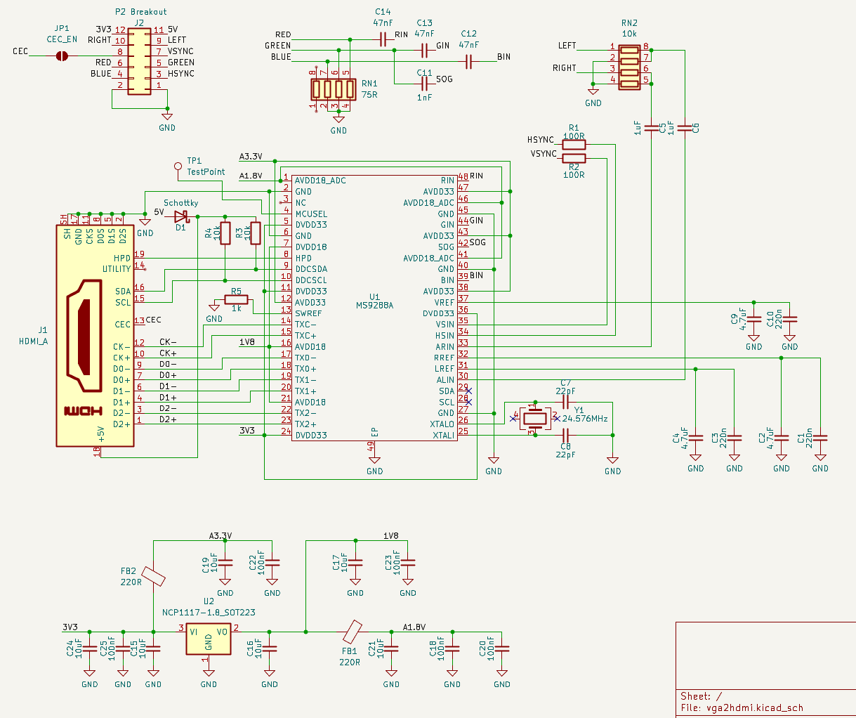
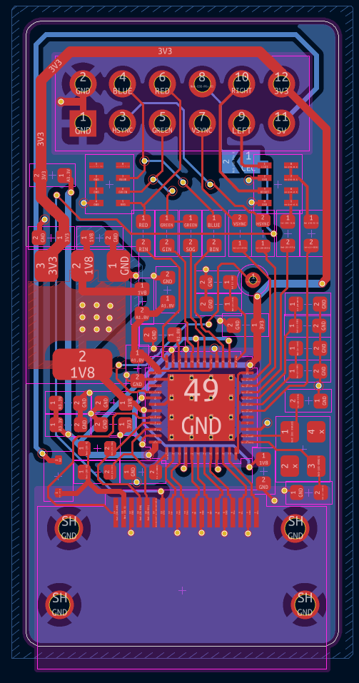
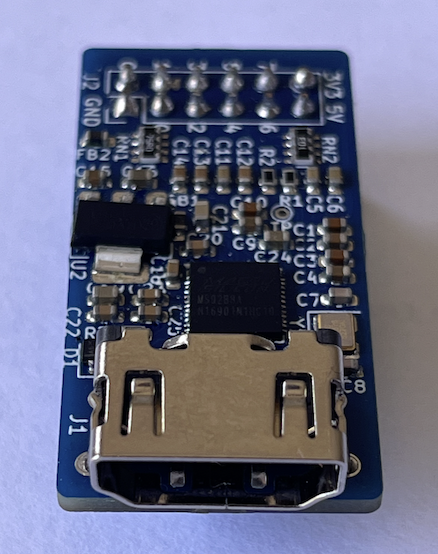
Here is the board render/layout: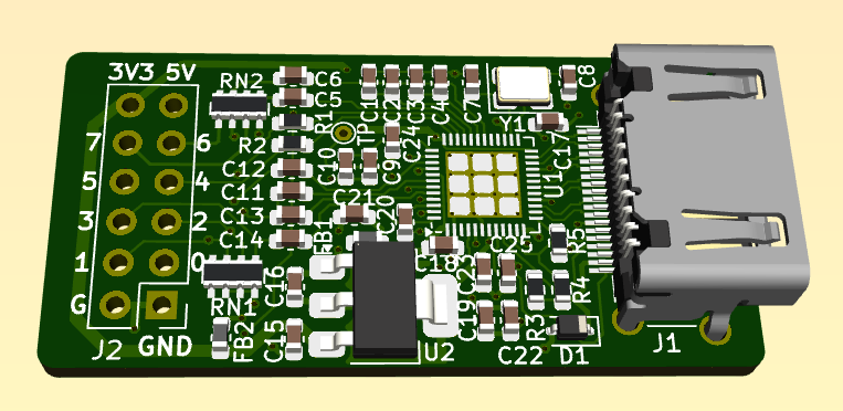
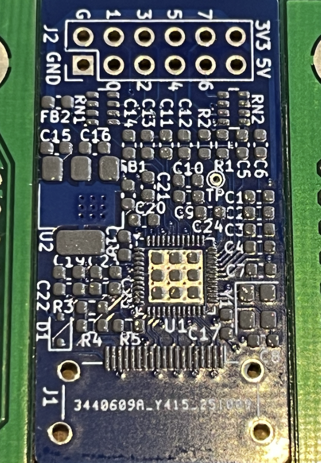
Here is the first PCB I received being populated & cooked, checked, tested: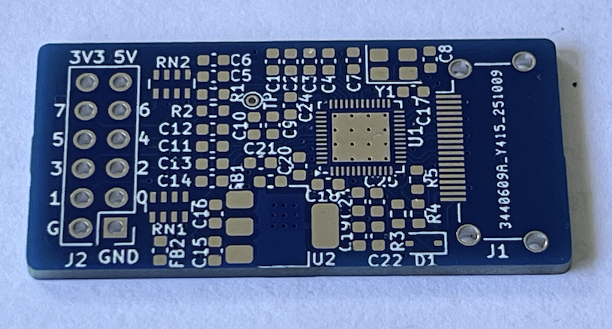
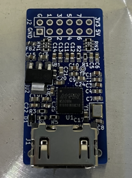
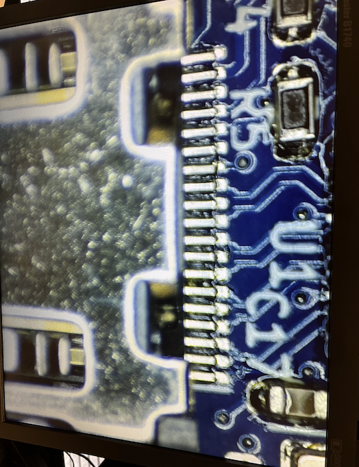
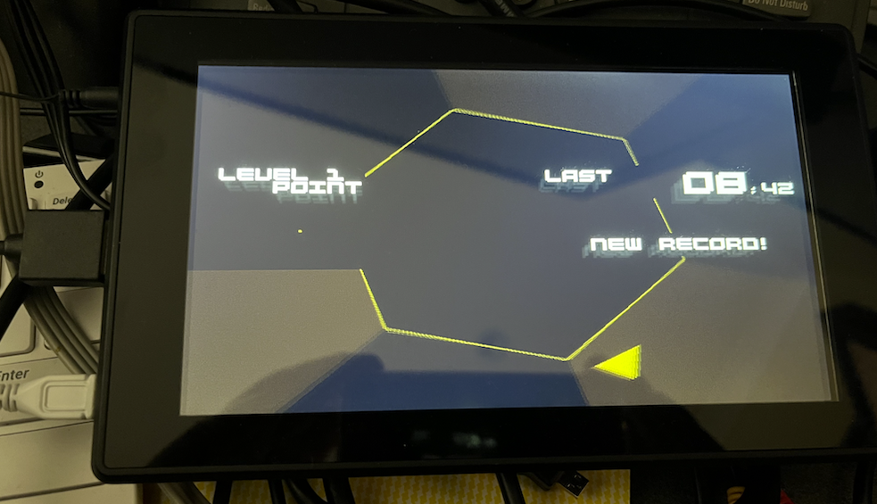
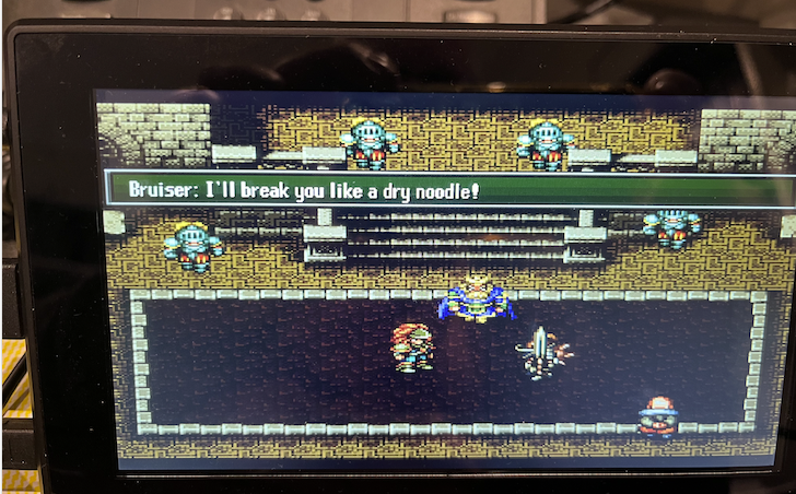
The connections were thankfully okay and it worked fine first go including audio which I tested on a small LCD screen with HDMI and headphone jack output. I ran @Wuerfel_21 's Spin Hexagon game with it outputting to small speakers initially. I've not yet tried component or SoG, although in theory it can do that too. I've tried various typical resolutions and they all worked with my Dell monitor specifically including:
- VGA
- SVGA
- XGA
- SXGA
- 1080p
How dependent on standard video timing this chip is vs how much the blanking and pixel clocks can be varied, I'm still not sure as I've not been looking at that aspect. I've also not yet attached it to my plasmaTV which we know is rather fussy with its audio source format etc. I've got to try to do that soon as well.
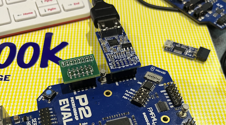
Also somewhat related to this and as probably mentioned somewhere in the Logicon thread I'm planning on making a separate board also using the MS9288A that takes VGA via my home-grown USB-C "Alternate mode" cable and converts it to HDMI and outputs to a display device with audio. I've already layed out a small board that does this, and it also carries regular USB to the handheld device for programming/downloads etc. Here's a render of what that looks like right now. The source VGA is still passed through from USB-C to DE-15 (via a triple video buffer device) as well as the converted HDMI.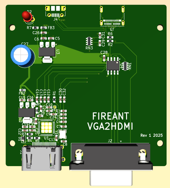
Comments
Just tried out feeding this chip some RGBS video (instead of RGBHV) and nothing was being displayed on my LCD HDMI monitor so it doesn't seem to support that and it apparently requires both H&V sync to be present, however the 3 pin Sync-on-green option worked with my driver. The colours seemed a little different with SoG (I need to check more) so it may require further work getting the right colourspace converter settings to setup the levels that balance the colour the same as RGBHV....TBD.
Given RGBS doesn't work, it may make sense to create a breakout board like this - this would allow either I2C access with SoG/component video only or full RGBHV video with no I2C. RGBHV drivers are a little more standard to implement than fiddling with the green levels (and so it's more compatible with existing P2 video drivers) although the P2 HW can of course output either type. Green channel's dynamic DAC range may get compressed with SoG and this could be why the colours are being messed up a bit.
8 P2 signals -
Can you try with the Sync-On-Green settings I have in my driver?
Last I checked those worked properly. There should be no dynamic range compression, because the DAC range is 1Vpp and the RGB video range is 0.7Vpp (as usual with VGA) - the remaining 0.3V becomes the sync pedestal. You may need to put the other channels on the same pedestal if the converter chip is bung.
@rogloh So it works? That is nice.
It appears to work, yep Still testing a few more things like audio -> Pioneer HDTV and more pixel clocks, plus true component, but the chip is spec'd for taking component or RGB so it should be fine.
I'll try later today when I get a chance. If your driver still uses really tight timing it may have issues, but if it uses regular VGA for example it should be good.
I also want to retest RGBS again but with sync at logic level instead of 0.7Vpp in case that mattered for the device.
Also I noticed in my schematic that audio coupling cap seems mighty low at 1nF. I would not normally have selected something that small, I think it was 1uF in reality, but now I'm worried about what was actually loaded into my board??? In general I'm not 100% sure on the audio levels with this circuit, and the resistors and caps there might need tweaking for optimal sound. EDIT: Just checked and it looks like I loaded 1nF by blindly following my schematic with that error. I'll have to swap those out I suspect.
Emulator/VNG's VGA/Soggy Line2x timing should be to VGA spec. Can do RGBHV(VGA), RGBS (CSync), Sync-On-Green RGB and YPbPr (in Rec. 601 and Rec. 709 flavours). Though some games really want 512 horizontal samples instead of 640. (Trials of Mana on MisoYume is a good test because it uses hires fonts, I think I talked about that before). I'd be interested in how it deals with that. A lot of ADCs deal poorly with this and the pixels become ugly. Also try Line3x mode (-> 720p-ish). I used to have Line4x and Line5x in the older drivers, but I got lazy and never ported them to the new VNG driver. But maybe that'll be important with a setup like this.
Looks like RGBS with TTL level sync instead of 0.7Vpp is still a no-go using my own video driver in Spin Hexagon, so it's RGBHV or SoG for VGA. Component should just be 3 pins as per usual. I also should try SDTV as well with that and potentially if interlaced conversion works too. It's late now so it will take a bit longer to setup something to try out some of your VNG stuff this weekend. Plus I want to see if this audio output is actually working on a real HDTV and how good/bad it sounds with the 1nF coupling caps on the board.
@Wuerfel_21 I got the board working with your older usbnew branch version in VGA2X and VGA3X modes. The YPrPb version didn't work, nothing came up on the HDMI LCD monitor. Audio worked although is at a relatively low volume - my RC network problem no doubt.
When I tried to upgrade to your latest master branch it's now failing to detect my SD card and I see a FS Mount error now. Probably something changed underneath, I'm just using the standard P2-EVAL SD card pins and didn't mess with that in the config file before and after the update. Wasn't there some probably some days ago with some change evanh made and the checked in code being bad for SD cards or something...?
Wait, that'd have to have been an ancient branch (of what software even? You didn't specify!). That certainly predates VNG. The old video driver only did 15kHz SDTV YPbPr, so I guess it doesn't support that.
??? Post config and exact thing you're trying to run. Please don't vaguepost.
@rogloh thanks for posting the schematic. Can't believe it's that simple... Thought for sure you'd need that i2c chip to make it work...
Wonder if this could work for P1 too...
Guess SOG is "sync on green"? Can that be left off? I.e., not populate C11?
Actually, wait a sec... If SOG can work, that would mean could deliver video and +5V over RJ45 cable. That could be handy for the PLC type stuff been doing...
Yep no support for that - it's probably designed for 50/60Hz progressive stuff given it takes in VGA.
Sorry I didn't mention which code, it's the NeoYume master branch (pulled from yesterday) that has the problem. Here's the config file I was using - with my own PSRAM board on a P2-Eval. The prior NeoYume branch that worked to prove out my setup was indeed rather old and called usbnew. After the full upgrade to the latest to test Sync-on-green etc it's now reporting a FS Mount error at the initial start up screen and nothing is shown in the game menu. I'd just changed the config.spin2 file to use the same USB/VGA/PSRAM pin settings as before (just in the new config file format). The SD pin settings are still at their defaults. Something seems to have changed in the SD card code. Could it be trying to do 4 bit mode even without the #define for that feature enabled? Or maybe I need to get a different SD card now as this is an older 2GB one (which has always worked before on the P2 - that's why I keep using it, others have had problems in the past).
Yes it's sync on green.
Haven't tried it without, but it's just a capacitor for the SoG input which is probably used if no syncs are detected on H&V. I suspect it could be run without if you don't use SOG but don't know for sure. If you run it, it probably needs to be connected. Green is fed to both pins. Seems harmless to keep in.
Works without i2c, but there's no reporting of the attached device's actual capabilities of course.
Don't see why it couldn't.
Bear in mind if you build one the audio levels may need adjusting. That schematic has the wrong values there for the caps. I'm going to desolder and add a 1uF instead of the 1nF on those coupling caps. The 10k ladder will drop the levels by half too to prevent possible overload at 3.3V and without a datasheet I'm not sure of the MS9288A's input impedance or if this has any AGC on the front etc. It's probably designed for line levels. With the 1nF 's fitted the levels seemed somewhat low but that was on an LCD monitor's headphone output at half volume. Other systems or TV's might be louder. Will find out more when I attached to my plasma TV
The plain SPI SD card code is part of the flexspin C library, so it updates regardless of what my code does. I haven't changed the SD mount code (or anything related to the upper code) in a long while, either. And I've certainly used the SPI driver in the meantime. Strange. Did you try disabling
#define _SDHC_45MHZ? I think the really old branch (it's two years out of date - this was when I was first implementing the new USB driver!) doesn't have that.Aha, that was it. Yeah. It's working now so I can test it out with SoG etc. Thanks!
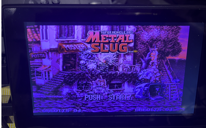
Just tried the MODE_SoG option in NeoYume. It syncs up but like I noticed with my driver the colour levels are not good, instead of white the menu screen has a purple hue to it as well as the game itself. Also the game is offset to the left a bit now and no longer centered by default. I guess the SoG timing is behaving somehow different to VGA with this, or the LCD needs re-centering for different inputs. Might be the capacitor values again.
The MODE_RGBS option also doesn't work at all too with the monitor not taking it and remaining black, like mine.
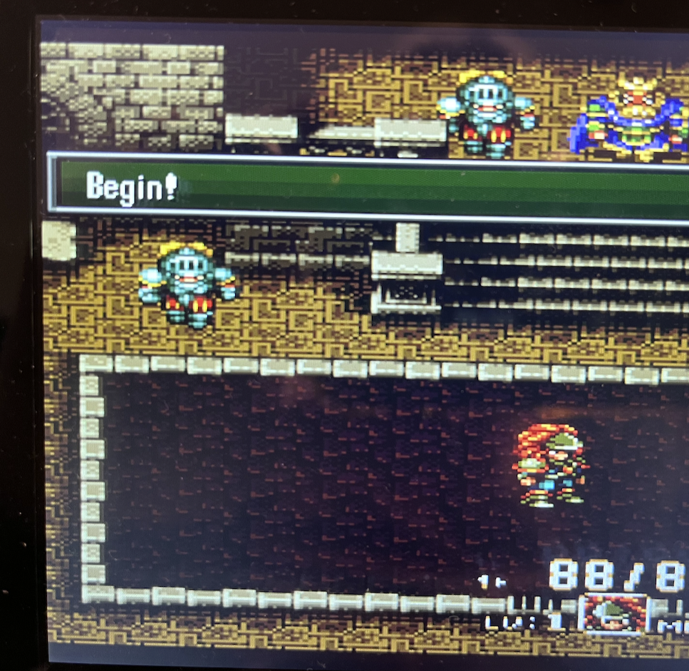
The MODE_YPBPR worked (offset to the left a little again) so this proves out component. Colours looked better and fairly normal. I tried both Rec601 and Rec709 and they both worked. Also tried SUBMODE_3X with the component mode but that didn't appear to sync up at all. It did with MODE_VGA though (which was centered nicely again - pictured below). Note this LCD panel is reporting 1360x768 input but is natively a 1024x600 panel so some scaling is going on. That resolution would be nice with my plasma which is 1368x768 natively.
If it looks crappy on Sync on Green and good on YPbPr, that just means it's set up to treat any soggyTM signal as YPbPr. That's what makes the signal turn purple, RGB misinterpreted as YUV.
(^ The VisonRGB E2S displaying a RGB signal while set to YUV mode)
The thing I'm rather interested in is pixel sampling.
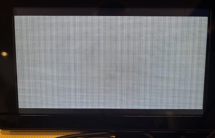
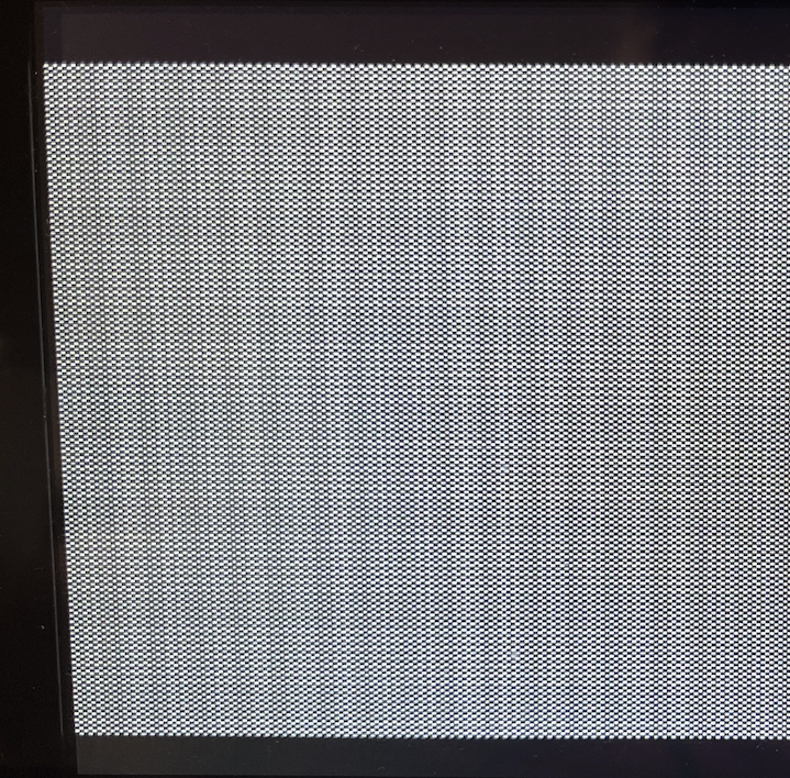
Can you load 240ptest and bring up the checkerboard screen?
Good to know - could well be something on the display side too - just a cheap LCD panel.
Yeah here it is in VGA mode with 3x and shows some aliasing pattern. But remember this is scaling as well on the panel too as it's 1024x600 panel.
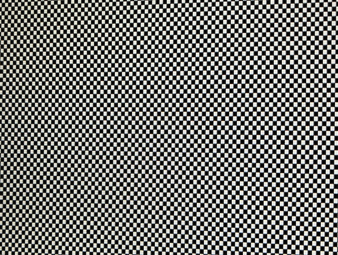
SUBMODE_2X looks far better when I zoom in - mainly vertical scaling going on but it's rather subtle in real life.
By the way the plasma wouldn't accept the 3X mode at all with VGA RGB. Yet to try other things but I need to go do other stuff now.
Also, because I had it running, I reconfirmed my memory that my ASUS PA248QV monitor supports Sync-on-Green for the VGA input (they still make/sell these, btw - can recommend buying it, great value).
As usual the Dell scales it beautifully.
SUBMODE_2X.
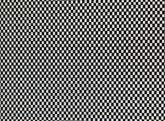
SUBMODE_3X.
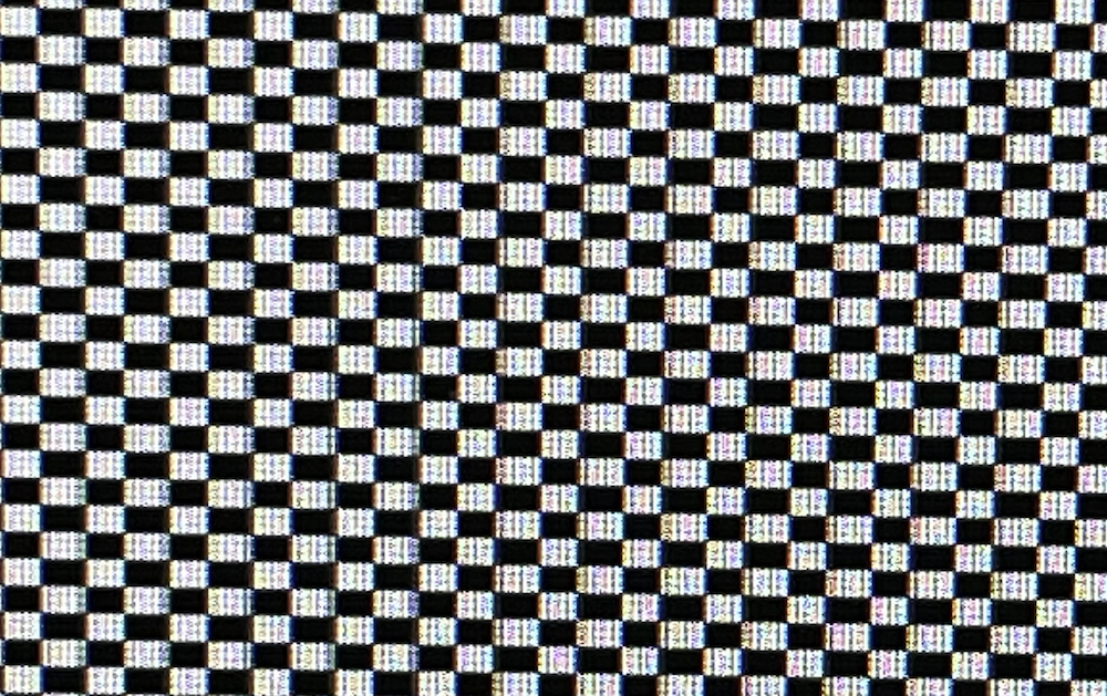
Here's the 3X mode in 1:1 pixels on the Dell (others were in fill aspect mode)
Now try either the Megadrive version of 240ptest (in MegaYume) with the 256x224 mode or the aforementioned Trials of Mana hires font stuff in MisoYume (I think I had you mess with that earlier, you should still have the file) - those deviate from standard sample rates, so it's interesting how those'd be handled.
Will do it later...
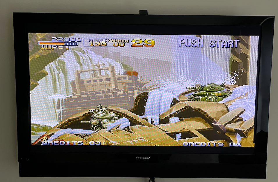
Just retested SUBMODE_3X on plasma TV after SUBMODE_2X worked. The 3X mode actually DOES work, I just had a poor connection at the 2x6 header initially. Once I wiggled it a bit it displayed a picture. It looks pretty good. Audio is also working on the plasma TV and it's reporting 1360x768 which it's happy with. Not sure if those diagonal colour artefacts are some sort of sampling issue from the TV to the camera. Audio levels were a bit low. I think I'll now change the coupling cap to 1uF and retry then short the 10k input resistor after that to see if that helps too.
EDIT: just changed audio caps to proper 1uF - now sounds way better with better bass. Prior circuit was just acting as a high pass filter. Levels okay for now without the resistor change.
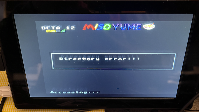
@Wuerfel_21 Tried latest MisoYume from master branch as of today in order to look at that Trials of Mana thing you wanted - this used to work with the SD card. But getting a bad SD access again for some reason. I have files in /MISOYUME folder on that card that used to get displayed and work from an older branch, but not for this latest fresh update from github. Config.spin2 modifications attached.
Uhhh, if it works on an older version, try bisecting where it stops working.
EDIT: Or just find an SD card that isn't cursed
Maybe the colorspace converter can automatically generate YPbPr?
That's the whole point of it. It's a highly flexible programmable block that can be configured to blend/modulate the four DAC level inputs to generate all the standard analog video formats: RGB, YPrPb, CVBS & Y+C.
Big problem with the CSC is that it can't do the opposite (convert YCbCr into RGB)
After messing about for a couple of hours on this with older MisoYume revisions etc, I have no clue why but by moving the DIP switches to making the P59 pullup high ON (all others left off), it now works and lets me read the folder. With the P59 pullup high switch left OFF it fails every time to even read the MISOYUME folder. NEOYUME and MEGAYUME worked fine without this DIP switch set like this on the very same micro SD card, and built with the same version of flexspin.
Must have something to do with having no electrical resistive load on this pin affecting the SD card (but at that specific named folder - weird). It's the DI pin so it would affect data going out to the card from the P2 output.
Any ran that Trials game and captured a couple of pics from the HDMI LCD. Seemed pretty readable/clean albeit stretched to fit the screen. RGBHV & SUBMODE_2X.