

Questions about PASM2 and register allocation (flexspin specific, maybe?)
 TMM
Posts: 22
TMM
Posts: 22
Hi there! I've been trying to work out how exactly PASM2 is supposed to work with regards to register allocation and such, and if there is a documented standard for this at all.
I have successfully written some relatively simple programs in p2asm, I've been using flexspin as the compiler if that matters, and I have several questions.
1) When assembling code at an orgh address, how does the assembler 'know' where it is going to be executed from? It could be cogexec'ed, hubexec'd, possibly copied into lut and executed from there. Are all p2asm jumps relative?
2) Similarly, how does the assembler "know" where to allocate the registers? If hubexec'ed then the location of the registers surely cannot be the same as if they are cogexec'ed? (I mean, they CAN be, but that'd be kinda silly, right? you'd be fragmenting the cog ram?)
I realize I could decode the binaries produced by flexspin to see what it does exactly. But I'd like to get some "non-empirical" information on this. Is there a spec on this? Is this all just implementation details?
I've attached a super dumb p2asm program I've been experimenting with to try and understand these details. (I realize I can use events for both loops ![]() this was just previously all in one loop for some other testing) The hubset / pin stuff at the top came mostly from the silicon docs, I hope I got that right. It does all seem to work.
this was just previously all in one loop for some other testing) The hubset / pin stuff at the top came mostly from the silicon docs, I hope I got that right. It does all seem to work.
Comments
orghassembles for hubexec,orgfor cogexec. If you use the wrong one, you might not immediately notice because most branches are relative by default and the binary code is compatible by-design.In your file you did it wrong because you're starting cog 1 in cogexec mode, but the code is assembled in orgh mode.
The registers are allocated where you want them to be (except for the special IN/OUT/DIR/PTR and such that are hardwired) in cog RAM.
I think you fundamentally didn't et itTM:
org Ndirective, it starts assembling code that could be loaded into cog RAM at address N (in cog RAM) - plainorgis the same asorg 0. This does NOT affect where in the hub image the code is placed, it just keeps on going.orghdirective, it starts assembling code for hubexec in-place.orgh Nwill attempt to zero-pad to address Norgh $1000to pad to that address and thenorg 0to start assembling cog codeorg). Any labels defined in cog mode evaluate to this cog address. (using the @ operator always gives the hub address where the label was assembled). Hub mode labels always evaluate to their hub addressVery much so! Thank you. That does make a bit more sense.
This isn't entirely clear to me yet. In my program I have 3 variables, and for instance
delay_countwhich is currently being used from code assembled for hubexec (thanks for that explanation! I had in fact not understood that either...) what cog ram address doesdelay_countend up in, and why? Based on what you said just now I'd expect it to be at 0 then? or is the address ofdelay_countactually just whatever address the end of the cog 0 (the stuff I called entry) code was?Alright, so the reason why the hubexec assembled code just happens to work in cogexec mode in my example is just that the jumps to
main_loop2anddelay_loopjust happen to be assembled as relative jumps then?Again thank you so much for taking the time to explain this. Where could I have learned this? I have been following the p2 assembly and spin2 documentation (the spin2 one mostly just for the constants tho), and it seems a bit light on these kind of low-level details.
The way you've written, yes, they end up after the code.
delay_countis at $020 (you can see this if you assemble with the -l flag to get a listing).Generally you'd use cog RAM like this: code first, initialized variables/data second, uninitialized variables last, then finish off with a
fitdirective. You can see this Data/code can really be mixed and are the same, but uninitialized registers (RES directive) must go at the end. This is obvious when you consider that the code/data part needs to be loaded in one contiguous block (either stopping at the end or loading unrelated data beyond the end). If RES is used in the middle, the cog address count and the assembler position desync and nothing makes sense anymore. (Flexspin will print a warning if it detects this). I've attached a file that's a good example of a typical Spin-usable PASM object that showcases this code/data/res layout.The use of delay_count in the second cog's code is erroneous, because $020 is only relevant to the first cog's memory layout. If you made that code any longer (remember, you're (also erroneously) starting into cogexec mode), you'd be overwriting one of your instructions that got loaded to $020. This is a general footgun hazard when having multiple different cog codes in the same asm file. If you look at big single file ASM projects I've done, you'll notice that all the labels have prefixes: https://github.com/IRQsome/NeoYume/blob/master/neoyume_lower.spin2 There has recently been a namespace feature added to flexspin to reduce the tedium, but I haven't gotten around to using it in a serious project yet.
Exactly.
Good question, honestly.
Do not cite the Deep Magic to me, Witch! I was there when it was written.-type situation.It's not trouble though for people who've done PASM on the P1, that one is the same but slightly less complicated due to lack of hubexec (everything is always executing from cog RAM).
TMM,
You're lucky those HUBSETs are working. Delete them all and use the special ASMCLK macro instead.
ORGH operates differently in pure pasm2. It actually places the binary at the specified hubRAM address, instead of just assembling for the target address. As Ada indicated, it will create padding in the assembled binary file. The binary file is loaded to hubRAM at address 0.
IMPORTANT: There is an explicit COGINIT instruction issued after the binary has loaded. Ether from the first stage ROM boot or from a second stage loader. The COGINIT copies the first 504 longwords from start of hubRAM into cogRAM of cog 0 then begins executing from register 0 of cog 0. This is why you are running in cogRAM from the start.
HubRAM execution (hubexec) is any simple branch away. There is no special setup for it. For program address space, hubexec goes from address $400 (2 kB) onwards. Cogexec from $0 to $3ff. Although there is something of a hole where the eight special registers are, $1f8 to $1ff. Putting code there would be tricky.
Data space is addressed differently. hubRAM is addressable from $0 onwards. CogRAM from $0 to $1ff. LutRAM from $0 to $1ff. HubRAM and lutRAM are both load/store access.
Generally yes, but I'm assuming they're in for the ✨educational✨ experience.
It actually loads 502 longs, as I said earlier. (this means if you're really strapped for space, you can extend your code into the interrupt vector area)
The more important distinction is that cog RAM and LUT RAM addresses have 32 bit granularity, but hubRAM addresses have the (more usual) 8 bit granularity. This has the odd effect that in cogexec mode, the PC increments by 1 every instruction, whereas in hubexec mode it increments by 4. (This granularity difference also causes some oddities with how relative branches are encoded to maintain that aforementioned property of relocateability)
Yeah, I fixed those and other issues. I do tend to make lots of those detail errors all the time. I don't double check myself until after posting. I guess it was the conceptual I was posting about. The details were added later.
Well you double corrected it to 504 loaded longs, which is infact correct. Those last 2 should not be used though, they're the PA/PB registers that are needed for other things (see also: https://p2docs.github.io/cog.html#cog-memory )
As for docs, Ada's transcriptions at https://p2docs.github.io/ are easier to load and browse than Chip's Google Docs. There is also the PDFs here - https://www.parallax.com/propeller-2/documentation/ The Assembly Language Manual is more fleshed out but still feels difficult to read.
Oops, looks like I still made a mistake back there. $400 is 1 k, not 2 k.
On that note, and adding to Ada's highlighting of byte vs longword granularity, when the COGINIT is issued it copies its 504 longwords from hubRAM address range of $0 to $7df. That's of course well beyond the minimum hubexec address of $400.
So you can get conflicts of ORGH $400 overlapping with the first ORG 0. Depends on how big that first pasm chunk is.
Hello @TMM, only for clarification, a register used on a P2 assembly instruction is always located in the cog RAM independent from the execution mode used.
You can show the generated memory locations by adding the option -l on the flexspin command to generate a list file (already mentioned by @Wuerfel_21). This shows you the addresses of your code in the program image after loading in hub RAM (first column), the addresses in the cog RAM (second column) and the generated code next to your source code.
As already mentioned by @evanh you can use the asmclk directive as first instruction in your code. This will generate the necessary hubset instructions like you did automatically by the compiler depending on _clkfreq in the CON block. Please don't use _clk_freq as name for the clock as it is not a known system constant and would not correct work with the asmclk directive and in general with all development tools. You can find this directive in the "Parallax Propeller 2 Documentation" hidden in some code examples. It was also discussed in the PNut/Spin2 thread.
Btw, you don't need a "hubset #0" to start your program, it is starting automatically after loading the program image into hub RAM.
Instead of using a hard coded address on coginit, you can add a label in the next line after "orgh $0600" and use this label with @, in your code example e.g. "coginit #1, ##@toggle".
Wow thank you all so much for the additional information. I think I largely understand what I didn't understand before now! This thread has given me some more questions tho...
Definitely true on the educational experience thing! But now that I looked into ASMCLK (which appears to only be documented in the SPIN2 doc?) I am confused as to how it works. I realize that just setting the The docs just say "The compiled clock mode, settable via HUBSET." It is unclear to me whether or not
_clckfreqconstant the compiler will magically do... something but even when runningflexpin -2 -lthe "something" includeshubset ##clkmode_ & !%11^Kwhat is##clkmode_where does it come from!ASMCLKwill use the external crystal or the internal one either. (I'm using the P2 platform from rayslogic) I guess I'd also have to set_xtlfreq?Does COGINIT always copy 504 longwords? The documentation just says it'll "start" I was vaguely assuming that there was some hidden magic to tell the cog how much data to copy. But reading the
COGINITpage in the PASM2 doc suggests you only give it a start address. I figured it "couldn't be that" because the docs say it completes in 2-9 instructions! How can copying 504 longwords only take so few instructions! But I'm guessing then that that is only the cost on the calling cog, and there will be some delay (presumably of 63 - 70 clocks?) before the new cog starts executing code?I'm trying to understand what is actually happening. Again thanks so much for all of your time, I realize that all of this is probably super old-hat for all of you.
_xtlfreqdefaults to 20_000_000. The compiler can automatically compute the correct clock mode based on target frequency and crystal frequency. Internal RC clock is fixed (not in PLL path) and also the default, so no need to set that specificallyYes, the cog being started will experience some delay. You can read the exact hardwired boot instruction sequence here: https://p2docs.github.io/mirror/p2silicon.html#boot-rom--debug-rom
Think asmclk adds three instructions to the start of the code to set the clock.
You can also do this yourself without using asmclk, but it’s a pain …
Yup, the macro was added when Spin2 was in early releases. There wasn't any separate assembly manual.
Chip has since depreciated having any explicit clock controls. It's actually now tacked on as an implicit prefixed chuck, but adding the ASMCLK is still allowed, afaik.
clkmode_andclkfreq_are nothing more than computed constants based on defaults and whatever values you specify in _clkfreq and _xinfreq/_xtlfreq. They're guaranteed to exist as constant symbols in the runtime, unlike _clkmode and _clkfreq.clkfreq_ will nominally be identical to any specified _clkfreq but can differ slightly when the crystal frequency (Defaults to 20 MHz but needs to be set with _xtlfreq or _xinfreq if a different crystal/oscillator is used) and the requested _clkfreq aren't an easy mult/div fraction.
Following all these instructions is mostly convention. In that the symbols are there for your convenience.
PS: There is a timing flaw in the sysclock PLL second divider selector when using DIVP=1 (%PPPP=%1111). HUBSET can lock up the Prop2 when not sequenced carefully. That's why I'd said you were luck you didn't have a problem at the outset. It's also why ASMCLK came into existence, albeit belatedly.
The old way was like this:
First this:
Then this:
DAT             org
origin
'
'
' Setup
'
'+-------[ Set Xtal ]----------------------------------------------------------+
' RJA:  New for real P2
                hubset  #0                              ' set 20MHz+ mode
                hubset  ##_SETFREQ                      ' setup oscillator
                waitx   ##20_000_000/100                ' ~10ms
                hubset  ##_ENAFREQ                      ' enable oscillator
'+-----------------------------------------------------------------------------+
Think you can see that ASMCLK is a lot easier...
That's broken too.
HUBSET #0placed first can't be counted on not to crash. If the second stage loader left you with %PPPP=%1111 then you're in trouble.And if you're already in RCFAST to begin with (power up state) then an initial HUBSET #0 has no use.
You're right, if you are using a board which has a different crystal than 20 MHz you need to set _xtlfreq with the used one.
Yes, for simplicity there will be always 504 longwords copied on COGINIT. The clocks mentioned in the doc are only for execution of the COGINIT instruction. You're right that there is some delay to load the data into the cog RAM and other overhead until the cog is starting with execution of code. In the docs I have not seen any time specification for this. Maybe @cgracey has it mentioned somewhere in a thread during development of P2.
Most users which are new to the P2 start programming with Spin2, therefore you're the exception. Such details you are asking for is more known by users programming mainly in assembly or C. Most of those users started with the P1 like me and therefore they know the differences in detail of both Propeller chips. Hence, for me it's more a repetition to recalling my knowledge. We all are learning always interesting news about the P2.
I like your questions and I'm happy to help. You're welcome.
COGINIT can also start at a hubRAM address directly as hubexec. There is a D operand bit to set for that. But the initial coginit doesn't use that option. Besides, having all the presets preloaded into registers is more compact anyway.
One solution that Chip really didn't want to do, for cost reasons, was to respin the design just for this. So he went with doing a software workaround. PS: He did technically sneak a rev C change but it wasn't a respin of the design. I believe he got away with it because it was a hand modification to one photo mask, someone was being nice.
Workarounds either do handovers in RCFAST or have a way to share clock mode setting. Those building the tools generally choose the latter since they are in control of both sides of the handover. It's not uncommon to have the clock mode already set for you.
There is also runtime system variables for
clkmodeandclkfreq(without any underscore) defined in both Spin and Spin2. Many other system developers have followed this convention. On the Prop1 there is explicit hubRAM addresses assigned for these system variables. On the Prop2, not so much, there are symbols that exist in hubRAM somewhere. There was quite a lot of discussions over this approach for the Prop2.For Spin2 it's the same for
clkmodeandclkfreqlike it is with Spin on Prop1. Here's from the Spin2 doc.That differs from what was actually agreed on. Everyone else, about a year earlier, followed a different location - That Chip had agreed to at the time. The end result is, as a user program, do not ever expect a specific address to be honoured. Use the symbols only.
PS: This stems partly from Spin2 being a late arrival to the Prop2. It isn't in the ROM the way it was with the Prop1.
Thanks everyone! That's a lot of useful information. For what I'm trying to do I kind of need to know where things end up in memory and such. (I'm trying to do a UNIX port to the P2, the ultimate goal is to run CDE on it. The basic idea is to have a unix kernel running natively on the cog, with userspace as a jitted vm that implements mmu and paging to extram and such)
I think based on all of this I have just one more question on this subject right now, when I look at
blink.lstafter switching toasmclkI seeBut what I don't see is what
##clkmode_is actually pointing to, or what actual bit pattern it is set to.Based on the further discussion on this thread I'm not sure now whether:
a) this is something that just for some reason doesn't show up in the listing, but is in fact a constant being put there by the assembler
b) this is a placeholder for a particular long in hubram that is used by convention, and is not spelled out
c) a combination of a, and b, where "some" location is picked in hubram, but it's not the same one per program but the name is
I think I understand everything else mentioned in this thread a lot better now. Thanks a lot everyone!
The ## means longword immediate operand via a prefixed AUGD instruction. So you're missing the first prefixing instruction.
I'm probably really missing something fundamental here, I understand that there's not enough room in a normal institution to encode more than 9 bits I think? So anything longer has to be loaded separately.
I just don't see in that assembly what the value of
clkmode_actually IS, regardless of how it eventually gets loaded into D for the hubset! 😄It is a brain twister. The hexadecimal format doesn't align nicely with 9 bits, and little endian doesn't help either.
Start with the easy one: WAITX ##20_000_000/100
200000 is 0b00000_000000000_110000110_101000000. I've divided it into lots of 9 bits (lsb justified) to help find this binary pattern in the two instructions. First one is the prefix, it contains the upper 32 - 9 = 23 bits in its lower 23 bits. An easy match of 0b00000_000000000_110000110
Second instruction contains the lower 9 bits: 101000000. But because it's the D operand then that's positioned from bit9 to bit17, which you can see here is a match
Keep in mind that the
clkmode_variable exists only during compilation in the compiler.What is confusing you is the missing assembly
augdinstruction in the listing. You can only see the generated code for it before thehubsetandwaitxinstruction. The indication for such instruction is the ## on an operand which means that the immediate value is greater than 9 bits.There exist also an
augsinstruction for an immediate value on the soure operand.Using the
augsoraugdinstruction you can provide a larger value to the following assembly instruction for the specific source or destination field. This is done by the compiler for you if you use ## on an operand. No need to write those instructions by yourself.The disadvantage is that you need two instructions to do this. Hence, additional two clocks necessary.
As alternative you can use a register in the variable area initialized with the value. Then you can reference it instead of using an immediate value,
Reversing the steps for clkmode_:
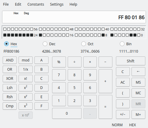
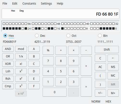
Prefixed AUGD of 0xff808007 for upper 23 bits 0b00000_001000000_000000111
Plus the HUBSET of 0xfd65f600 for lower 9 bits 0b011111011
Combined: 0b00000_001000000_000000111_011111011
Sysclock setting format:
E = %1 (PLL engaged and tracking XI)
C = %10 (XI/XO engaged, 15pF per pin)
S = %11 (PLL as clock source selected)
D = %000000 (Divide by 1)
M = %0000001110 (Multiply by 15)
P = %1111 (Divide by 1)
So, 20 MHz crystal assumed x 15 / 1 / 1 = 300 MHz sysclock.
Oh.... The very fundamental thing I missed was that the listing just kept some symbolic names ( the fact that it has
##20_000_000/100really should have been a hint)Thank you so much for your patient and excellent explanations. I really should have just manually decoded the hexedecimal instead of just reading the text and confusing myself. The implicit
augdand the fact that the literal just still has the symbolic name in the assembly listing really threw me off and it shouldn't have.Thank you so much! I will strive to ask better questions in the future
It's been a while since anyone new went straight to the metal.