I guess the VGA Hsync could be provided from the LCD Hsync. Big problem there is that this LCD uses weird timings that won't quite work for VGA. But having no external display/capture kinda blows, doesn't it?
Difficult problem. (The VGA hsync can be made to come from any DAC0 pin, btw)
@Wuerfel_21 said:
I guess the VGA Hsync could be provided from the LCD Hsync. Big problem there is that this LCD uses weird timings that won't quite work for VGA. But having no external display/capture kinda blows, doesn't it?
Difficult problem. (The VGA hsync can be made to come from any DAC0 pin, btw)
Yeah external would be nice - hard to solve though.
Ideally what I'd like to do is use USB-C instead of the PropPlug output and use that Alternate mode to carry HDMI but not enough P2 pins now unless I go down to 8 bit PSRAM and the cables all want to use the DP Alt Mode as an intermediate step - why!? Or I try to reuse some LCD pins for HDMI out - problem is the actual bus load for the HDMI as the LCD would still be connected to those pins and I don't really want to add extra buffer chips etc. I could use one of those Parallel RGB to to TMDS chips but there is really limited space and that chip is large. I could probably fit a micro HDMI connector in but I lose the ability to reprogram and/or download to the embedded SD card. I think I'd stick to just USB-C.
Ok I might still keep port A bits 0, 1 free. TBD. In fact I do have 3 free pins down there because DE is not required in this implementation. That would allow an analog VGA out if the sync pins are shared (as an either/or output due to restricted LCD timing). Again, what micro connector supports it? Actually a custom USB-C adapter to VGA perhaps could do that over a USB-C cable....hmm. Not as nice as direct cable to TV, but maybe better than nothing.
So something like this mapping could work out perhaps:
bit 0 - HSYNC
bit 1 - Blue
bit 2 - Green
bit 3 - Red
bit 4 - VSYNC
bit 5 - PIXELCLK
bit 6 - LEFT_PWM
bit 7 - RIGHT_PWM
This has an added advantage in that it is sort of compatible with the A/V breakout board pin mapping.
Custom cable it is I guess. For capture weird timings don't really matter, at least with those Datapath cards. Though I haven't been able to solve the annoying video offset problem. I think the Windows driver doesn't suffer it?
Yeah I'm gonna look into the USB-C with VGA as an option - only issue is it might possibly be a danger to plug a USB-C cable into a PC if VGA is being output at the time. RGB signals are limited to 0.7V or so but I still don't imagine the USB-C chips will be too happy with it, and I'd need to carry LVCMOS levels for syncs and possibly audio unless DACs are used (which may mess up internal audio though if amp is enabled or headphones are used). I could use the USB2 pins for those 3.3V signals I guess.
@Wuerfel_21 One possible way to get HDMI out might be those cheap VGA to HDMI converter boxes. If they worked with this tight video timing I guess we could try to use make use of that. Be cool if that chip fit inside this box, but I still need the connector space for it and it's at a premium. Might make more sense to use one externally even though not as nice a solution. https://goughlui.com/2019/02/02/quick-teardown-mini-vga2hdmi-converter/
Getting there on the next board. It's probably about 95% routed but that last 5% will of course take longer. I ended up adding USB-C to this which will allow programming and updating the internal SD card files via USB at some point - I have jumpers that can select paths via FTDI or through P62/P63 directly. I also added a bunch of solder jumpers for optionally sending VGA over a custom USB-C cable which may be helpful at some point. They are accessible on the bottom layer. Maybe a CM201 can be modified to accept input via USB-C connector and then output HDMI.
Here's the top layer - it's filling up a bit now, I just have some more USB-C routing to do and a general tidy up/DRC etc. I've also gone to 4 layers on the FireAnt board. With any luck the heat from the layers on the top P2 board can wick down via the grounded metal solder nuts and the two larger ground planes on my board will help dissipate the heat. But that's going to be an interesting test when we get to it - the P2 sitting above is facing outwards so adding some sort of external metal heatsink plate is still possible if needed. Hope it doesn't need an external fan!
@Wuerfel_21 , was chatting with @Tubular today and we talked about reversible USB-C cables carrying VGA signals. I wonder in your drivers whether we can make good use of Sync-on-Green as a way to deal with cable reversal or if there's any issue there. Looking at the colour channel mapping in the prior post's diagram, instead of using the TX2 pair for H/V syncs green is replicated on both TX1+/- as well as TX2+/- pins. Then if the USB-C cable is reversed then only red and blue colours would be swapped and this would be immediately visible but it would still work. Also L&R channels would be swapped but that's tolerable also. Another way to keep it working but avoiding sync-on-green is to use both CC1/CC2 pins for a single combined (H^V) sync single.
Note that doing this is obviously completely non-standard and is just for a customized breakout application using a USB-C interface cable to output VGA, not for normal USB-C operation. Ideally though it wouldn't interfere with a USB-A to USB-C cable at all and the D+/D- pins could still be used for a USB prop plug via the on-board FTDI chip. I could either use CC1/CC2 for combined sync, and the SBUS pins for audio or vice versa. Not sure which is better - perhaps SBUS is better for audio if no pull down resistors are present so the DAC mode can be used, but for this 5k1 resistor value it's unlikely to matter anyway.
Yes, I have support for Soggy Sync and C-Sync in my driver. Though to what extent monitors support it... IIRC my ASUS 1920x1200 monitor supports C-Sync, don't remember if it does soggy. The VisionRGB card certainly does all 3 (H/VSync, CSync, Soggy). Though it's certainly not universal. IIRC there's some issue with how soggy sync is generated (for both Sync-on-Green and YPbPr) that prevents it from running alongside HDMI (Csync is okay). Will have to figure out if that holds for LCD as well (which doesn't have that need to escape raw 10b codes)
EDIT: BTW, swapping red/blue (or Pb/Pr) in software is pretty ez.
Yeah I'll probably aim to target the C-sync way, at least as an option. All my monitors seem to accept that mode. My driver also does it as well. I believe C-sync can also be driven at video levels too. Am sort of hoping that the LCD without vsync might shut down and stop the internal amp so that would let us use DAC mode externally but not 100% sure yet.
UPDATE: with respect to the pinning of the cable and the audio/sync, I figured out it would need to be the combined HVSYNC on CC1 & CC2 with audio on SBUS because inside the USB-C cable there is only one CC line connected so stereo audio would not work there. So I'll just put the video sync on those pins. It means that CC1 and CC2 are shorted together after the socket (I'll populate only a single 5k1 resistor or possibly do 2x10k in parallel).
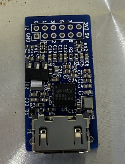
Whipped up another P2 related PCB since I'll be sending the P2 FireAnt one in a few days so I have an opportunity to make this as well. This one (if it works) will convert VGA to HDMI at up to 165MHz pixel clocks. The usual resolutions from 640x480 to 1920x1080 should be supported and stereo audio is encoded but some testing will be required to find the limits. The board is fairly densely packed now as I may have to hand solder some of it if component changes are needed because I'm using 0603's so I have some chance of doing so. But the 6x6mm QFN-48 is gonna be fun. Will be getting the stencil for sure and using the hotplate again. Probably should have chosen a smaller regulator but I'm just not sure how much current this will take and being linear and dropping 1.5V as heat, it could get quite hot. I do know it'll be less than 500mA as these converters can be USB powered.
I've added CEC as an option (solder jumper on back) for the spare pin after the 5 VGA pins then followed by left and right DAC pins so it's compatible with the A/V breakout to some extent. Just needs a bit of a touch up for the diff pairs and to sort out a few more DRCs then it'll be ready to go.
I haven't got any around the house to test, but I wouldn't trust these VGA digitizer chips to automatically detect the correct clock/phase even on standard modes. LCD monitors almost never get this 100% right in their auto-adjust feature either, unless you bring up a checkerboard pattern and then do it. This probably just guesstimates it on signal detect.
@Wuerfel_21 said:
Though I'd stick with just breaking VGA out. Then you can plug it into a VisionRGB or smth like that and dial it in for pixel-perfect capture.
I'm still going to do VGA on the P2 FireAnt. This board is something else I've been planning on making for a while and for P2-EVAL use.
What I might do though for the FireAnt use is retrofit a USB-C breakout board to this CM201 case and a 2x3 slide switch to select VGA from the external connector or USB_C pins and then I could use it to input VGA from the GPi Case 2W and convert to HDMI or flip the switch and then output VGA from the GPi Case 2W as well as audio. If I wire in the D-/D+ to the micro USB-B which powers it (currently unconnected) it would let me use that for PropPlug too, all over the same USB-C cable which is handy. I'll probably need a small RC filter to convert from PWM to DAC (or use DAC mode itself if the amp can be shutoff without VSYNC perhaps).
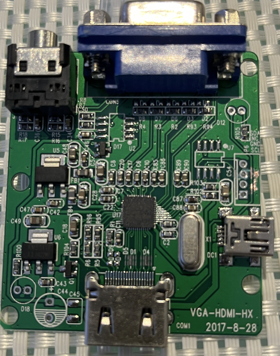
Here's what was inside my CM201 case when I opened it up. The unpopulated components seem to be a DDC EEPROM going to the VGA pins, a power LED & more caps, a LED for HPD indication, and another I2C which connects to the chip - maybe some sort of additional firmware for more HDMI features (HDCP encryption stuff perhaps?), plus a header for programming that.
The main P2 FireAnt PCB design is now done and passes DRC. Our plan now is that it will go out in the next day or so for manufacturing along with that other VGA2HDMI breakout board I've since completed as well.
I shielded the ~150MHz PSRAM clock with ground planes and ensured layers above and below had no other signal crossings and tried to make the same path length to each PSRAM device to minimize the clock skew although the data line lengths would still vary a little. Some of this work is probably moot as there is going to be some length variation from the board above that holds the P2 anyway, but whatever. I also added a series resistor in the clock line to try to match impedance if that helps sharpen rise times and improve signal integrity and performance with 64MB fitted (which has 2 PSRAM chip loads on each data pin, and 8 loads on the clock pin). We'll see if that helps or hinders it. Might have to run at sysclk/3 in the worst case.
DAC based VGA (along with audio) is output to the USB-C high speed data pins and secondary bus channels by default but can be removed by cutting some jumpers. USB-C should still be reversible and something would display but red/blue would be flipped along with audio channels (in theory this could be reversed in software to accommodate that).
Update: This reminds me, still need to doublecheck the pixel clock can be generated by a SmartPin on the same pins already controlled by the COG driving the video from its streamer. If that fails this board needs a pin adjustment.
EDIT: just tried it on bit4 of portA which currently also outputs H/V/DE in the same byte and it seems to work.
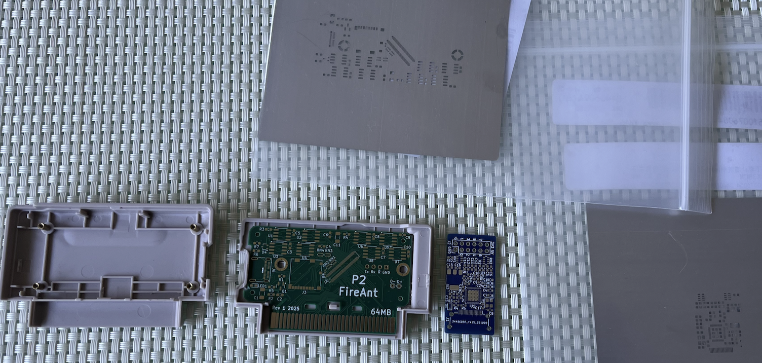
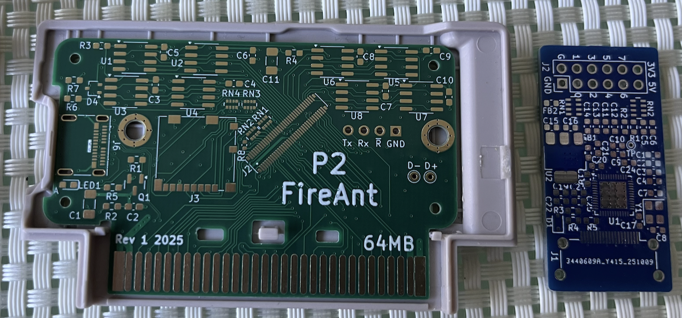
Boards arrived today. Still waiting on some parts before we can start to assemble but happy with the outcome. The ENIG finish looks nice on the 4 layer FireAnt board and final dimensions are all good with things lining up where they should. Not looking forward to soldering down the fine pitched (0.4mm?) mezz connector and full USB-C port connector but I did order the metal stencil for it. The upper board is also done but that's Tubular's creation to reveal at some point.
The other separate VGA2HDMI breakout is gonna be fun to make and try out, except it's little QFN.
It also makes sense to see if a P2 chip could fit roughly where the mezz connector is and see if it is routable with 4 layers - may not be, not sure. The uSD & associated resnets etc could all be moved over to the right side and the space that leaves along with the unused solder nut holes could be occupied by the extra flash/regulator parts and routing required. I might have a play with layout there too while I wait for my parts to arrive to see if anything is viable to fit in the gap. But this first version will be tested with the mezz board fitted which has all been designed to work together assuming we can get the connectors soldered down nicely. The good thing is the signals around the mezz essentially follow the same pin ordering of a P2 so a general routing change for that may not be too hard to do. Without an upper board there is probably a lot of room for a metal heatsink plate also, if required.
Did a test place and it would be a challenge but it might be possible to squeeze in the P2. Would still need regs, the zillion bypass caps and boot flash, plus an FTDI/serial chip or go native USB serial via a boot flash image. The top row of the P2 would route pretty nicely to the PSRAM as is. More existing components on the left would move closer to the SD freeing more space. Solder nuts would not be required either although they could be good to mount a metal heatsink plate on top of the P2 if needed. If this is routable on a 4 layer board I'm interested in trying it down the line as it makes things simpler to construct.
Some progress over the weekend although I've not been able to use the forums much due to lots of 504 Gateway Timeout errors this week. Parts arrived and I soldered up the board. Now waiting for Lachlan's board to be assembled to test further.
Some pics of assembly and final outcome of the hotplate soldering which I'm really happy with. The 0402 resistor R8 was tricky but just achievable - same as the resnets.
Very impressed by your soldering results. This could be super useful where you want to power the P2 at lower clock frequencies to save power, rather than 297 MHz to get HDMI.
It also provides a 'legit' HDMI claim, which is good from a manufacturer point of view (to be able to claim proper compliance)
Yes, my board... I'll get to it, maybe tomorrow, otherwise on the long weekend.
Haha, HDMI compliance. I think I misread some of the docs when I made my driver, tried to go for an unfortunate optimization with the preamble timing and that made it not work right on a very select subset of TVs. I think the way to go with this sort of thing is to just conspiciously avoid ever mentioning "HDMI" in the documentation/marketing and just say "Digital A/V port" or something. Like how a lot of products have a "TF card" slot.
Probably the main benefit for me is being able to output digital video at higher resolutions up to 1080p60 from the P2 using the small breakout directly - although external options are already available to do that too (e.g. Simplecom CM201). Also I plan to make another variant for the FireAnt handheld that can output HDMI and VGA simultaneously from the USB-C source and provide a USB2.0 path to the PropPlug inside for downloads/debug/power.
I'm yet to test the audio encoding capability. My fussy Plasma is probably a good test of that.
Also, like the point Ada mentioned, in the MS9288A chip product page they just call it a "HD transmitter" so I'm not even sure they've even claimed any HDMI compliance.
Spent the arvo out at @Tubular 's , and he made up his P2 board that mates to the mezzanine connector of my FireAnt - so it's now ready to test in earnest. Preliminary tests got the P2 detected over a USB cable via pogo pins and my USB-C connector and we also know both regulators are working. Very happy with the soldering outcome and fine placement he has achieved - no shorts seen at all. So far there has only been one minor problem found - an ordering snafu with the crystal oscillator which turned out to be 64MHz instead of 20MHz but we can probably work around this until the correct one arrives and we rework it.
Lachlan will post details of his board soon in another thread and I believe there is a presentation planned for next week's Prop live forum.
Apologies for this really poor lighting photo (it's night here now) which shows it attached to my board underneath - the extra resistor was just for initial clip on power testing when running as a standalone setup and will get removed soon. It fits nicely with the cartridge case closed too.
Still need to test out flash and then the P2 IO, the 32MB of PSRAM and my SD mode SD card circuit, plus the GPi Case 2W's VGA/audio/game controller interface and also see if it works up at 340MHz and the thermals. If some heat transfer is needed there is room for a heatsink plate above the P2. We are sort of hoping with the large number of layers on his board and through to my own board once solder nuts are attached will help spread the heat from the P2 and transfer some away.
Does anyone know the limits of the XIN clock mode for the P2? I have this 64MHz oscillator module feeding the P2 (instead of 20MHz by mistake) and am having issues trying to switch to it and use it. It seems to be running at a really low frequency and the PLL can't really use it correctly either which is weird. If I manually run this snippet which is waitx delay tuned to toggle a LED pin at something around 1 Hz I can then estimate the operating frequency. I've tried different settings for the P2 clock source including RCSLOW, RCFAST, XIN, and XIN+PLL.
For RCSLOW I get around 20kHz as expected
hubset #1 ' enable rcslow
rep #3, #0
waitx ##10000 ' 1/2 second rcslow
drvnot #54 ' LED pin
For RCFAST I see the P2 operating around 24MHz as expected
hubset #1 ' enable rcslow
rep #3, #0
waitx ##12000000 ' 1/2 second rcslow
drvnot #54 ' LED pin
For XIN (cc=01, ss=10) I see it operates about 100kHz!
hubset  ##%0_000000_0000000000_0000_01_10   ' cc=01, ss=10
rep #3, #0
waitx ##50000 ' 1/2 second
drvnot #54 ' LED pin
For XIN (cc=10, ss=10) I see it operates about 40kHz!
hubset  ##%0_000000_0000000000_0000_10_10   ' cc=10, ss=10
rep #3, #0
waitx ##20000 ' 1/2 second
drvnot #54 ' LED pin
For XIN (cc=11, ss=10) I see it operates about 30kHz!
hubset  ##%0_000000_0000000000_0000_11_10   ' cc=11, ss=10
rep #3, #0
waitx ##15000 ' 1/2 second
drvnot #54 ' LED pin
Then if I enable the PLL I can see the frequency rises but still not to where I'd expect. Again the cc bits seem to affect the frequency. The PPPP bits also affect it, as expected by their dividing ratios but the MM..M and DD..D bits don't seem to have any real effect at all and I varied them both by quite a bit looking for changes which were not observed.
E.g When PPPP=1111 I see the P2 operates around 2.56MHz with cc=01 - and it also changes similar to the above when varying cc bits.
hubset #$0                                 'set 20 MHz+ (RCFAST)
hubset ##%1_001111_0001100111_1111_01_00   'enable crystal+PLL, stay in RCFAST mode
hubset ##40_000_000/100                    'wait ~10ms for crystal+PLL to stabilize
hubset ##%1_001111_0001100111_1111_01_11   'now switch to PLL
rep #3, #0
waitx ##1280000 ' 1/2 second
drvnot #54 ' LED pin
When PPPP=0000 I see the P2 running around 1.28MHz with cc=01
hubset #$0                                 'set 20 MHz+ (RCFAST)
hubset ##%1_001111_0001100111_0000_01_00   'enable crystal+PLL, stay in RCFAST mode
hubset ##40_000_000/100                    'wait ~10ms for crystal+PLL to stabilize
hubset ##%1_001111_0001100111_0000_01_11   'now switch to PLL
rep #3, #0
waitx ##640000 ' 1/2 second
drvnot #54 ' LED pin
Don't really understand what is happening here unless it's just a bad signal getting into the P2 or the P2 tops out a smaller input frequency below 64MHz. @evanh I think you've done some work examining the P2 clocking - do you know what the XIN pin can take or if I'm missing something important based on the results above? I was sort of hoping that I could divide down the input by 64 and multiply by 252 with PPPP=1111 to get 252MHz for testing. But I can't reach any real high frequencies.
Maybe we have issues with the input impedance at the XIN pin given the variation of cc bits affecting load capacitance seems to be changing the outcome. The oscillator module feeds the P2 via a zero ohm series resistor straight into the XIN pin, i.e. DC coupled. We probed it yesterday and saw a reasonable sinusoid approximation feeding the series resistor at 64MHz swinging widely above 3.3V and below 0V as some overshoot was noticed. So it was a strong signal - hopefully not too strong!
Not sure if I can make progress with this oscillator unless I'm doing something silly with the P2 clock settings. May just have to test with RCFAST I guess.
@Tubular said:
Hmm. Well, we can always put a 20 MHz xtal there while we wait for 20 MHz osc
Yeah we may have to if I can't resolve the clock settings. With RCFast I did just try talking to the flash chip and it seems to be erasing and reprogramming a sector with a counting pattern, so that's something. Also I buzzed out all P2 IO to the gold edge fingers from the pin pads on your board and they connect so the mezz is passing these signals though okay. I can probably try the PSRAM at RCFast for basic signal connectivity but it's not an ideal test. I can also probably try out the SD with RCFAST to prove wiring is routed through. After that not sure we can do much with RCFast. I could perhaps try a VGA to the handheld screen running at ~24MHz LOL. It may work.
EDIT: I wonder if the VCCIO bypass cap for the PLL is ok or if shorted to ground - maybe that could mess up the PLL operation?
@rogloh said:
Does anyone know the limits of the XIN clock mode for the P2? I have this 64MHz oscillator module feeding the P2 (instead of 20MHz by mistake) ...
Hardware manual specs (page 9) says 0-180 MHz. So basically the full operating range of the Prop2 itself.
@Tubular said:
Hmm. Well, we can always put a 20 MHz xtal there while we wait for 20 MHz osc
Yeah we may have to if I can't resolve the clock settings. With RCFast I did just try talking to the flash chip and it seems to be erasing and reprogramming a sector with a counting pattern, so that's something. Also I buzzed out all P2 IO to the gold edge fingers from the pin pads on your board and they connect so the mezz is passing these signals though okay. I can probably try the PSRAM at RCFast for basic signal connectivity but it's not an ideal test. I can also probably try out the SD with RCFAST to prove wiring is routed through. After that not sure we can do much with RCFast. I could perhaps try a VGA to the handheld screen running at ~24MHz LOL. It may work.
EDIT: I wonder if the VCCIO bypass cap for the PLL is ok or if shorted to ground - maybe that could mess up the PLL operation?
I doubt it, but you can toggle P28 or P29 and make sure it goes high.
P30 and P31 have a serial resistor, we just put 0 R shorts on there. All those 4 GPIO are on easy to access pins/pads
@rogloh said:
Does anyone know the limits of the XIN clock mode for the P2? I have this 64MHz oscillator module feeding the P2 (instead of 20MHz by mistake) ...
Hardware manual specs (page 9) says 0-180 MHz. So basically the full operating range of the Prop2 itself.
Yeah so it should be possible to make it work at least at 64MHz. But it seems to run far slower than that which is really strange. I wonder about whether the signal is getting in fully - will have to check those resistor paths and that the IO in that nibble works.


Comments
I guess the VGA Hsync could be provided from the LCD Hsync. Big problem there is that this LCD uses weird timings that won't quite work for VGA. But having no external display/capture kinda blows, doesn't it?
Difficult problem. (The VGA hsync can be made to come from any DAC0 pin, btw)
Yeah external would be nice - hard to solve though.
Ideally what I'd like to do is use USB-C instead of the PropPlug output and use that Alternate mode to carry HDMI but not enough P2 pins now unless I go down to 8 bit PSRAM and the cables all want to use the DP Alt Mode as an intermediate step - why!? Or I try to reuse some LCD pins for HDMI out - problem is the actual bus load for the HDMI as the LCD would still be connected to those pins and I don't really want to add extra buffer chips etc. I could use one of those Parallel RGB to to TMDS chips but there is really limited space and that chip is large. I could probably fit a micro HDMI connector in but I lose the ability to reprogram and/or download to the embedded SD card. I think I'd stick to just USB-C.
Ok I might still keep port A bits 0, 1 free. TBD. In fact I do have 3 free pins down there because DE is not required in this implementation. That would allow an analog VGA out if the sync pins are shared (as an either/or output due to restricted LCD timing). Again, what micro connector supports it? Actually a custom USB-C adapter to VGA perhaps could do that over a USB-C cable....hmm. Not as nice as direct cable to TV, but maybe better than nothing.
So something like this mapping could work out perhaps:
bit 0 - HSYNC
bit 1 - Blue
bit 2 - Green
bit 3 - Red
bit 4 - VSYNC
bit 5 - PIXELCLK
bit 6 - LEFT_PWM
bit 7 - RIGHT_PWM
This has an added advantage in that it is sort of compatible with the A/V breakout board pin mapping.
Custom cable it is I guess. For capture weird timings don't really matter, at least with those Datapath cards. Though I haven't been able to solve the annoying video offset problem. I think the Windows driver doesn't suffer it?
Yeah I'm gonna look into the USB-C with VGA as an option - only issue is it might possibly be a danger to plug a USB-C cable into a PC if VGA is being output at the time. RGB signals are limited to 0.7V or so but I still don't imagine the USB-C chips will be too happy with it, and I'd need to carry LVCMOS levels for syncs and possibly audio unless DACs are used (which may mess up internal audio though if amp is enabled or headphones are used). I could use the USB2 pins for those 3.3V signals I guess.
@Wuerfel_21 One possible way to get HDMI out might be those cheap VGA to HDMI converter boxes. If they worked with this tight video timing I guess we could try to use make use of that. Be cool if that chip fit inside this box, but I still need the connector space for it and it's at a premium. Might make more sense to use one externally even though not as nice a solution.
https://goughlui.com/2019/02/02/quick-teardown-mini-vga2hdmi-converter/
Getting there on the next board. It's probably about 95% routed but that last 5% will of course take longer. I ended up adding USB-C to this which will allow programming and updating the internal SD card files via USB at some point - I have jumpers that can select paths via FTDI or through P62/P63 directly. I also added a bunch of solder jumpers for optionally sending VGA over a custom USB-C cable which may be helpful at some point. They are accessible on the bottom layer. Maybe a CM201 can be modified to accept input via USB-C connector and then output HDMI.
Here's the top layer - it's filling up a bit now, I just have some more USB-C routing to do and a general tidy up/DRC etc. I've also gone to 4 layers on the FireAnt board. With any luck the heat from the layers on the top P2 board can wick down via the grounded metal solder nuts and the two larger ground planes on my board will help dissipate the heat. But that's going to be an interesting test when we get to it - the P2 sitting above is facing outwards so adding some sort of external metal heatsink plate is still possible if needed. Hope it doesn't need an external fan!
@Wuerfel_21 , was chatting with @Tubular today and we talked about reversible USB-C cables carrying VGA signals. I wonder in your drivers whether we can make good use of Sync-on-Green as a way to deal with cable reversal or if there's any issue there. Looking at the colour channel mapping in the prior post's diagram, instead of using the TX2 pair for H/V syncs green is replicated on both TX1+/- as well as TX2+/- pins. Then if the USB-C cable is reversed then only red and blue colours would be swapped and this would be immediately visible but it would still work. Also L&R channels would be swapped but that's tolerable also. Another way to keep it working but avoiding sync-on-green is to use both CC1/CC2 pins for a single combined (H^V) sync single.
Note that doing this is obviously completely non-standard and is just for a customized breakout application using a USB-C interface cable to output VGA, not for normal USB-C operation. Ideally though it wouldn't interfere with a USB-A to USB-C cable at all and the D+/D- pins could still be used for a USB prop plug via the on-board FTDI chip. I could either use CC1/CC2 for combined sync, and the SBUS pins for audio or vice versa. Not sure which is better - perhaps SBUS is better for audio if no pull down resistors are present so the DAC mode can be used, but for this 5k1 resistor value it's unlikely to matter anyway.
Yes, I have support for Soggy Sync and C-Sync in my driver. Though to what extent monitors support it... IIRC my ASUS 1920x1200 monitor supports C-Sync, don't remember if it does soggy. The VisionRGB card certainly does all 3 (H/VSync, CSync, Soggy). Though it's certainly not universal. IIRC there's some issue with how soggy sync is generated (for both Sync-on-Green and YPbPr) that prevents it from running alongside HDMI (Csync is okay). Will have to figure out if that holds for LCD as well (which doesn't have that need to escape raw 10b codes)
EDIT: BTW, swapping red/blue (or Pb/Pr) in software is pretty ez.
Yeah I'll probably aim to target the C-sync way, at least as an option. All my monitors seem to accept that mode. My driver also does it as well. I believe C-sync can also be driven at video levels too. Am sort of hoping that the LCD without vsync might shut down and stop the internal amp so that would let us use DAC mode externally but not 100% sure yet.
UPDATE: with respect to the pinning of the cable and the audio/sync, I figured out it would need to be the combined HVSYNC on CC1 & CC2 with audio on SBUS because inside the USB-C cable there is only one CC line connected so stereo audio would not work there. So I'll just put the video sync on those pins. It means that CC1 and CC2 are shorted together after the socket (I'll populate only a single 5k1 resistor or possibly do 2x10k in parallel).
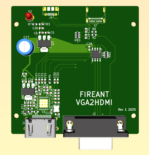
Whipped up another P2 related PCB since I'll be sending the P2 FireAnt one in a few days so I have an opportunity to make this as well. This one (if it works) will convert VGA to HDMI at up to 165MHz pixel clocks. The usual resolutions from 640x480 to 1920x1080 should be supported and stereo audio is encoded but some testing will be required to find the limits. The board is fairly densely packed now as I may have to hand solder some of it if component changes are needed because I'm using 0603's so I have some chance of doing so. But the 6x6mm QFN-48 is gonna be fun. Will be getting the stencil for sure and using the hotplate again. Probably should have chosen a smaller regulator but I'm just not sure how much current this will take and being linear and dropping 1.5V as heat, it could get quite hot. I do know it'll be less than 500mA as these converters can be USB powered.
I've added CEC as an option (solder jumper on back) for the spare pin after the 5 VGA pins then followed by left and right DAC pins so it's compatible with the A/V breakout to some extent. Just needs a bit of a touch up for the diff pairs and to sort out a few more DRCs then it'll be ready to go.
I haven't got any around the house to test, but I wouldn't trust these VGA digitizer chips to automatically detect the correct clock/phase even on standard modes. LCD monitors almost never get this 100% right in their auto-adjust feature either, unless you bring up a checkerboard pattern and then do it. This probably just guesstimates it on signal detect.
I've had some success with this working out ok on the CM201 product I have here, but you might be right it may not be perfect at all times.
Though I'd stick with just breaking VGA out. Then you can plug it into a VisionRGB or smth like that and dial it in for pixel-perfect capture.
I'm still going to do VGA on the P2 FireAnt. This board is something else I've been planning on making for a while and for P2-EVAL use.
What I might do though for the FireAnt use is retrofit a USB-C breakout board to this CM201 case and a 2x3 slide switch to select VGA from the external connector or USB_C pins and then I could use it to input VGA from the GPi Case 2W and convert to HDMI or flip the switch and then output VGA from the GPi Case 2W as well as audio. If I wire in the D-/D+ to the micro USB-B which powers it (currently unconnected) it would let me use that for PropPlug too, all over the same USB-C cable which is handy. I'll probably need a small RC filter to convert from PWM to DAC (or use DAC mode itself if the amp can be shutoff without VSYNC perhaps).
Here's what was inside my CM201 case when I opened it up. The unpopulated components seem to be a DDC EEPROM going to the VGA pins, a power LED & more caps, a LED for HPD indication, and another I2C which connects to the chip - maybe some sort of additional firmware for more HDMI features (HDCP encryption stuff perhaps?), plus a header for programming that.
The main P2 FireAnt PCB design is now done and passes DRC. Our plan now is that it will go out in the next day or so for manufacturing along with that other VGA2HDMI breakout board I've since completed as well.
I shielded the ~150MHz PSRAM clock with ground planes and ensured layers above and below had no other signal crossings and tried to make the same path length to each PSRAM device to minimize the clock skew although the data line lengths would still vary a little. Some of this work is probably moot as there is going to be some length variation from the board above that holds the P2 anyway, but whatever. I also added a series resistor in the clock line to try to match impedance if that helps sharpen rise times and improve signal integrity and performance with 64MB fitted (which has 2 PSRAM chip loads on each data pin, and 8 loads on the clock pin). We'll see if that helps or hinders it. Might have to run at sysclk/3 in the worst case.
DAC based VGA (along with audio) is output to the USB-C high speed data pins and secondary bus channels by default but can be removed by cutting some jumpers. USB-C should still be reversible and something would display but red/blue would be flipped along with audio channels (in theory this could be reversed in software to accommodate that).
Update: This reminds me, still need to doublecheck the pixel clock can be generated by a SmartPin on the same pins already controlled by the COG driving the video from its streamer. If that fails this board needs a pin adjustment.
EDIT: just tried it on bit4 of portA which currently also outputs H/V/DE in the same byte and it seems to work.
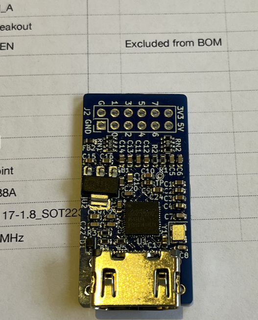
Boards arrived today. Still waiting on some parts before we can start to assemble but happy with the outcome. The ENIG finish looks nice on the 4 layer FireAnt board and final dimensions are all good with things lining up where they should. Not looking forward to soldering down the fine pitched (0.4mm?) mezz connector and full USB-C port connector but I did order the metal stencil for it. The upper board is also done but that's Tubular's creation to reveal at some point.
The other separate VGA2HDMI breakout is gonna be fun to make and try out, except it's little QFN.
It also makes sense to see if a P2 chip could fit roughly where the mezz connector is and see if it is routable with 4 layers - may not be, not sure. The uSD & associated resnets etc could all be moved over to the right side and the space that leaves along with the unused solder nut holes could be occupied by the extra flash/regulator parts and routing required. I might have a play with layout there too while I wait for my parts to arrive to see if anything is viable to fit in the gap. But this first version will be tested with the mezz board fitted which has all been designed to work together assuming we can get the connectors soldered down nicely. The good thing is the signals around the mezz essentially follow the same pin ordering of a P2 so a general routing change for that may not be too hard to do. Without an upper board there is probably a lot of room for a metal heatsink plate also, if required.
Did a test place and it would be a challenge but it might be possible to squeeze in the P2. Would still need regs, the zillion bypass caps and boot flash, plus an FTDI/serial chip or go native USB serial via a boot flash image. The top row of the P2 would route pretty nicely to the PSRAM as is. More existing components on the left would move closer to the SD freeing more space. Solder nuts would not be required either although they could be good to mount a metal heatsink plate on top of the P2 if needed. If this is routable on a 4 layer board I'm interested in trying it down the line as it makes things simpler to construct.
Some progress over the weekend although I've not been able to use the forums much due to lots of 504 Gateway Timeout errors this week. Parts arrived and I soldered up the board. Now waiting for Lachlan's board to be assembled to test further.
Some pics of assembly and final outcome of the hotplate soldering which I'm really happy with. The 0402 resistor R8 was tricky but just achievable - same as the resnets.
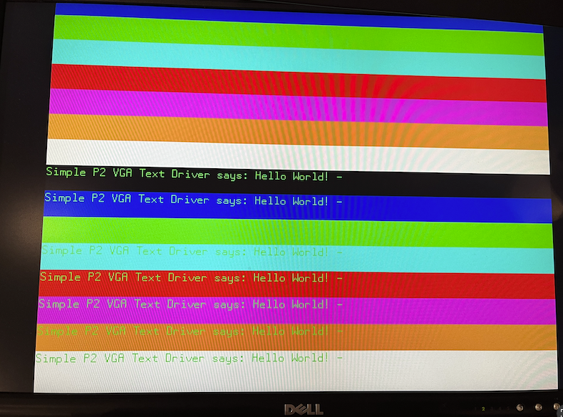
Also made that VGA2HDMI board and it worked first go which I'm pleased with.
Pasted and ready to cook
Hotplate cooked
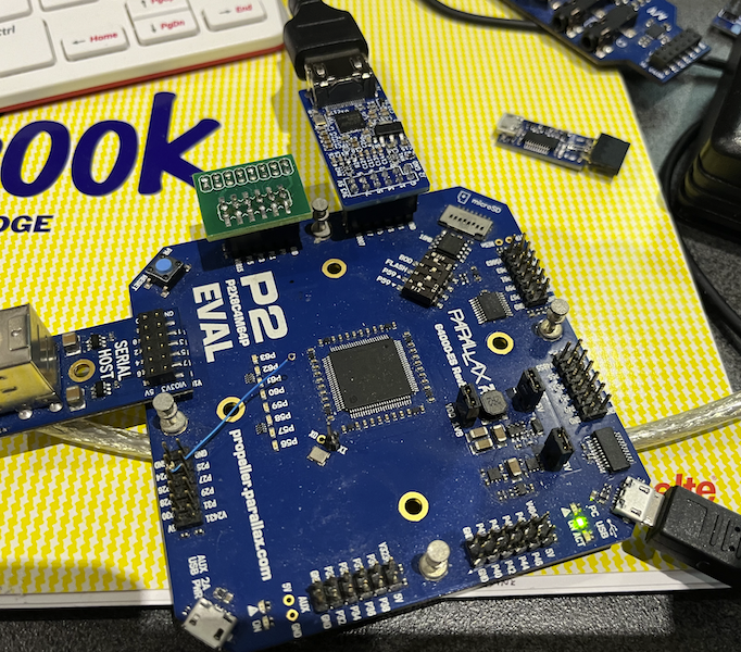
Test setup
Board feeding DVI input of my monitor from P2 VGA source converted to digital video
Very impressed by your soldering results. This could be super useful where you want to power the P2 at lower clock frequencies to save power, rather than 297 MHz to get HDMI.
It also provides a 'legit' HDMI claim, which is good from a manufacturer point of view (to be able to claim proper compliance)
Yes, my board... I'll get to it, maybe tomorrow, otherwise on the long weekend.
Haha, HDMI compliance. I think I misread some of the docs when I made my driver, tried to go for an unfortunate optimization with the preamble timing and that made it not work right on a very select subset of TVs. I think the way to go with this sort of thing is to just conspiciously avoid ever mentioning "HDMI" in the documentation/marketing and just say "Digital A/V port" or something. Like how a lot of products have a "TF card" slot.
Probably the main benefit for me is being able to output digital video at higher resolutions up to 1080p60 from the P2 using the small breakout directly - although external options are already available to do that too (e.g. Simplecom CM201). Also I plan to make another variant for the FireAnt handheld that can output HDMI and VGA simultaneously from the USB-C source and provide a USB2.0 path to the PropPlug inside for downloads/debug/power.
I'm yet to test the audio encoding capability. My fussy Plasma is probably a good test of that.
Also, like the point Ada mentioned, in the MS9288A chip product page they just call it a "HD transmitter" so I'm not even sure they've even claimed any HDMI compliance.
Spent the arvo out at @Tubular 's , and he made up his P2 board that mates to the mezzanine connector of my FireAnt - so it's now ready to test in earnest. Preliminary tests got the P2 detected over a USB cable via pogo pins and my USB-C connector and we also know both regulators are working. Very happy with the soldering outcome and fine placement he has achieved - no shorts seen at all. So far there has only been one minor problem found - an ordering snafu with the crystal oscillator which turned out to be 64MHz instead of 20MHz but we can probably work around this until the correct one arrives and we rework it.
Lachlan will post details of his board soon in another thread and I believe there is a presentation planned for next week's Prop live forum.
Apologies for this really poor lighting photo (it's night here now) which shows it attached to my board underneath - the extra resistor was just for initial clip on power testing when running as a standalone setup and will get removed soon. It fits nicely with the cartridge case closed too.
Still need to test out flash and then the P2 IO, the 32MB of PSRAM and my SD mode SD card circuit, plus the GPi Case 2W's VGA/audio/game controller interface and also see if it works up at 340MHz and the thermals. If some heat transfer is needed there is room for a heatsink plate above the P2. We are sort of hoping with the large number of layers on his board and through to my own board once solder nuts are attached will help spread the heat from the P2 and transfer some away.
Does anyone know the limits of the XIN clock mode for the P2? I have this 64MHz oscillator module feeding the P2 (instead of 20MHz by mistake) and am having issues trying to switch to it and use it. It seems to be running at a really low frequency and the PLL can't really use it correctly either which is weird. If I manually run this snippet which is waitx delay tuned to toggle a LED pin at something around 1 Hz I can then estimate the operating frequency. I've tried different settings for the P2 clock source including RCSLOW, RCFAST, XIN, and XIN+PLL.
For RCSLOW I get around 20kHz as expected
For RCFAST I see the P2 operating around 24MHz as expected
For XIN (cc=01, ss=10) I see it operates about 100kHz!
For XIN (cc=10, ss=10) I see it operates about 40kHz!
For XIN (cc=11, ss=10) I see it operates about 30kHz!
Then if I enable the PLL I can see the frequency rises but still not to where I'd expect. Again the cc bits seem to affect the frequency. The PPPP bits also affect it, as expected by their dividing ratios but the MM..M and DD..D bits don't seem to have any real effect at all and I varied them both by quite a bit looking for changes which were not observed.
E.g When PPPP=1111 I see the P2 operates around 2.56MHz with cc=01 - and it also changes similar to the above when varying cc bits.
When PPPP=0000 I see the P2 running around 1.28MHz with cc=01
Don't really understand what is happening here unless it's just a bad signal getting into the P2 or the P2 tops out a smaller input frequency below 64MHz. @evanh I think you've done some work examining the P2 clocking - do you know what the XIN pin can take or if I'm missing something important based on the results above? I was sort of hoping that I could divide down the input by 64 and multiply by 252 with PPPP=1111 to get 252MHz for testing. But I can't reach any real high frequencies.
Maybe we have issues with the input impedance at the XIN pin given the variation of cc bits affecting load capacitance seems to be changing the outcome. The oscillator module feeds the P2 via a zero ohm series resistor straight into the XIN pin, i.e. DC coupled. We probed it yesterday and saw a reasonable sinusoid approximation feeding the series resistor at 64MHz swinging widely above 3.3V and below 0V as some overshoot was noticed. So it was a strong signal - hopefully not too strong!
Not sure if I can make progress with this oscillator unless I'm doing something silly with the P2 clock settings. May just have to test with RCFAST I guess.
Hmm. Well, we can always put a 20 MHz xtal there while we wait for 20 MHz osc
Yeah we may have to if I can't resolve the clock settings. With RCFast I did just try talking to the flash chip and it seems to be erasing and reprogramming a sector with a counting pattern, so that's something. Also I buzzed out all P2 IO to the gold edge fingers from the pin pads on your board and they connect so the mezz is passing these signals though okay. I can probably try the PSRAM at RCFast for basic signal connectivity but it's not an ideal test. I can also probably try out the SD with RCFAST to prove wiring is routed through. After that not sure we can do much with RCFast. I could perhaps try a VGA to the handheld screen running at ~24MHz LOL. It may work.
EDIT: I wonder if the VCCIO bypass cap for the PLL is ok or if shorted to ground - maybe that could mess up the PLL operation?
Hardware manual specs (page 9) says 0-180 MHz. So basically the full operating range of the Prop2 itself.
I doubt it, but you can toggle P28 or P29 and make sure it goes high.
P30 and P31 have a serial resistor, we just put 0 R shorts on there. All those 4 GPIO are on easy to access pins/pads
Yeah so it should be possible to make it work at least at 64MHz. But it seems to run far slower than that which is really strange. I wonder about whether the signal is getting in fully - will have to check those resistor paths and that the IO in that nibble works.
Roger.