What went wrong with the original plug? Was it just lots of use wore it out?
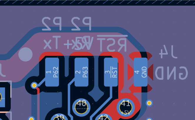
These male PropPlug pins on the FireAnt were always problematic and I did some silly things.
1) I used SMD instead of Through Hole - tried to ameliorate this by putting some in pad vias (not shown here in this variant but was in the final gerbers sent to manufacturing), but not on the ground pad due to 5V directly below. I should have just moved the 5V net to make room and used through hole pins which are always stronger and just trimmed the top surface where the Edge connector hits the pins.
2) I removed the small black plastic stiffener between the 4 pins to allow the boards to sandwich closer and fit the cartridge - should have just filed the plastic down a bit
3) I cut the pins down a couple of mm as they stuck out farther than I wanted and kept spiking me
4) I used a heavy USB cable on the PropPlug which stressed it a lot moving it around on my desk.
5) I yanked the PropPlug out a lot during testing to move this device about and into more comfortable positions to use
6) I pushed onto the GND pin for a probe earth for the scope and this stressed it more and ripped out the GND pin
7) superglue debacle
and so on...
I probably did more harm to the PropPlug than the FireAnt though.
@rogloh said:
I will do when I can retest again. I actually want to test without inversion now for sync pins.
What I mean is that it's now a mask in the cmode thing, so it's easy to toggle it.
Yeah I saw the code you changed in that area, good move. I do wonder if the CLK PIN should also have that possibility too and also something to adjust its phase in general clock granular units for tweaking.
I want to say the current setup is supposed to sync up perfectly, but it could also just be "ok this worked for LCD6 testing that's good enough" and I forgot to fix it later. I did definitely do perfect clock phase for my LCD816 demo driver, need to check that later (currently busy in other endeavours)
The edge might be centered in the middle of a bit but the device might want a positive clock or a negative clock. The GPi seems to want negative edges. In some situations a slight tweak might be helpful if the clock path on a board is loaded down or something, but I'd agree the polarity setting is more important than absolute phase.
I just checked, the LCD816 thing was more complicated.
So really need to get that logic probe setup going (problem is that this will want the hueg P2Edge breakout and at the moment I have everything full of other P2 boards and sewing utensils and also VHS I'm supposed to transfer)
You should see my desk - it's literally overflowing right now, everything I touch falls off the desk. I have too much going on and need a day off just to cleanup.
Ok, PropPlug is working again and I'm back in business.
From what I've tried out today I just can't make the DE signal have any effect whatsoever, positive or negative, with HSYNC/VSYNC either floating or high or low. The DE signal is definitely present on the scope, and also fixing it high or low has zero effect also. If I have floating H/V pins the screen will draw weird pixels and vertical lines randomly, it just won't sync to it. I'm suspecting the LCD in this GPi device is somehow strapped or fixed internally to just use V+H syncs and the back porch sizes are known by the controller. I did discover that you can allocate more pixels/lines across both sync intervals and front porches, but the back porch of both vertical and horizontal must be fixed to 2 lines and 20 pixels respectively in order to center the screen correctly. Weird.
So far it's not a show stopper at least for NeoYume, and in fact it looks like NeoYume already adds top/bottom black bars it so even if you need to add several more VSYNC lines you probably can and the screen would still be fully visible on the display, just shifted down slightly.
I still want to test my own driver with these timing restrictions to check there won't be issues. I know my text driver is working okay with this timing, but not sure about graphics modes, especially with PSRAM which might need to have a couple of blanking lines prior to the first drawn line in order to pipeline the graphics - it might be right at the limit. Similar with a mouse sprite active and horizontal blanking. Although supporting my existing video driver is not a real priority here, more so having some emulation working.
Update: changed wxpin value used by OPN audio cog to 5 from 10 for NCO_DUTY parameter. Seems to not buzz or have audio issues and sounds decent.
Now I just need to convince myself I can layout a board that will run ok at 340MHz in this enclosure, with 64MB PSRAM.
There is a bit more space than a P2 Edge inside. I could probably gain about 5mm height and 10mm width. But these are next level layout skills I may not yet possess.
But if I could fit an existing P2-Edge inside that'd be a game changer.
Aww no DE auto-alignment.
What timing values are you using now? Any further code mods from my NeoYume branch? (other than the audio thing). I can try porting the display stuff to the other VNG driver variants (MegaYume, MisoYume, Tempest, P1Classics). Need to think harder about how to best handle audio stuff going forward, so you're on your own there for a bit.
Also @Rayman can probably share what he did for the P2Platform to make the layout work. Then just imagine that, but with the smaller PSRAM chips.
(Or maybe find and utilize the mythical 64Mx8 HyperRAM)
So here we ended up getting a 1/16 divider (even lower clock speed)
There's always black bars and the video is limited to a 8:7 window (no power left to scale it up with acceptable quality)
Try a game with HiRes modes (Trials of Mana uses Mode 5 heavily - check if the text is readable. Make sure you have the newer ~6MB collection ROM or the japenese original - the older ~4MB english patch versions don't actually have hires fonts)
I now remember why this VNG variant was WIP and not merged into the main p2port branch
Same timings as NeoYume (copy-paste mentality - but the port has way different timing from the original anyways - it actually manages to hit full frame rate rather consistently)
For LCD6 I had dithering here because the 18bpp banding was atrocious, not sure if enough time to run this at 640x480, so currently absent.
Aww no DE auto-alignment.
What timing values are you using now? Any further code mods from my NeoYume branch? (other than the audio thing). I can try porting the display stuff to the other VNG driver variants (MegaYume, MisoYume, Tempest, P1Classics). Need to think harder about how to best handle audio stuff going forward, so you're on your own there for a bit.
I have been messing with lots of random values in different video tests so I can't say I've settled on any specific values except for keeping back porches fixed at 2 and 20 for V&H respectively. For example this is the timing as it exists right now...but it can also be changed to the extreme of just one sync pulse for H&V and all the extra pixels shoved into the front porch. For a laugh I should test the extreme of 1 FP pixel, all extra pixels in HSYNC, and 20 BP pixels. Maybe that works too LOL.
timing_lcd24_640x480
long VIDEO_CLKFREQ  ' CLKFREQ
long 2              ' active line multiplier
long 5-2+2-1+12 '12          ' V front porch
long 30 '2              ' V sync
long 2 ' 34             ' V back porch
long 0              ' extra pillar
long 640            ' blank line
long 16'+55'+36             ' H front porch
long 37+55 '1'56             ' H sync
long 20 '56             ' H back porch
long $0924924a      ' Sync NCO
long $0924924a>>1   ' Pixel NCO
long 0              ' Alt-res NCO
long 14 + (14>>1)<<16 ' pixel clock pulses
long 1
I do need to take your latest NeoYume code from a fully clean slate without all my own hacks and see what else was needed to make it work. For example I think I drove the audio pins low so the pins don't float before they are initialized - otherwise there are bad noises output. The NCO_DUTY Smartpin change (from DAC) is also needed and I use WXPIN of 5 as you recommended.
Plus at some point it'd be good to hook that extra "menu" pin on the console to restart (as well as the safe powerdown option). We could have it polling whether some controller button down "pattern" matches in usbnew for a second or two, then it takes this action. The RasPi running Recalbox makes you press the menu and start buttons at the same time for about 1/2 second and then it will go back to the menu. You'd not really ever do that by mistake in a game so it's pretty safe.
By the way, I found that I can re-download a new test program serially with loadp2 after a prior session and avoiding the SD mount error instead of power cycling the whole SD card as I was doing before. I just need to wait maybe a few seconds after a PropPlug reset (when exiting from the console in loadp2) for the capacitance to discharge or something and the SD card to recover itself once it's pins float. Haven't tried another SD card yet, but I'm happy that this is possible. It's a PITA to power off every time I download otherwise.
@Wuerfel_21 said:
Also @Rayman can probably share what he did for the P2Platform to make the layout work. Then just imagine that, but with the smaller PSRAM chips.
Yeah they'll need to be small chips for 64MB.
(Or maybe find and utilize the mythical 64Mx8 HyperRAM)
That is an idea, would use less pins too, but probably needs more testing prior to committing to such a thing.
As to testing all your other systems, I'll try to take a look through when I get time and see what I can run as that appears to be a whole lot of stuff to try right now and I've got other priorities/projects ongoing as well. If your other emulators do also work, I think it'd be cool to have a selection option screen for a front end - I vaguely thought you had discussed such a thing already, although I also think I recall you mentioning that the code was not really restartable at one point quite a while ago. Perhaps some flash or SD emulator selection app could make a nice front end (or better yet, remembers your prior emulator selection and directly loads that app, unless some button is held in which case it presents a full list of emulators you can run). Just musing here about what would make a great standalone environment for a portable device like this.
By the way are you planning to try something like this too yourself and pick up a GPi Case 2W now we know NeoYume can be run on it or do you want to know if the other emulators work first? It can always be run with a Pi Zero / 2W if you have issues, so all is not lost after purchasing one - but that is a slower system to boot compared to your emulators. The Gerbers I posted can be utilised with cheap PCB manufacturers like JLCPCB or PCBWay etc if you wanted to make a PCB and do what I did to a spare cartridge. Only tricky part is the USB connector to solder, may need hot air gun for that or fine soldering iron tip.
I don't know if/how long a full blow FireAnt P2 variant will take to make, could be a while, if it's even attempted. Almost tempted to try to squeeze a real P2-Edge inside using folded flat flex to solder directly onto the P2 Edge pins as an alternative pathway which might be much faster and more available to other people interested in such a thing...TBD.
Aww no DE auto-alignment.
What timing values are you using now? Any further code mods from my NeoYume branch? (other than the audio thing). I can try porting the display stuff to the other VNG driver variants (MegaYume, MisoYume, Tempest, P1Classics). Need to think harder about how to best handle audio stuff going forward, so you're on your own there for a bit.
I have been messing with lots of random values in different video tests so I can't say I've settled on any specific values except for keeping back porches fixed at 2 and 20 for V&H respectively. For example this is the timing as it exists right now...but it can also be changed to the extreme of just one sync pulse for H&V and all the extra pixels shoved into the front porch. For a laugh I should test the extreme of 1 FP pixel, all extra pixels in HSYNC, and 20 BP pixels. Maybe that works too LOL.
I kept that in mind when I calculated all the new timings for the variants
timing_lcd24_640x480
long VIDEO_CLKFREQ  ' CLKFREQ
long 2              ' active line multiplier
long 5-2+2-1+12 '12          ' V front porch
long 30 '2              ' V sync
long 2 ' 34             ' V back porch
long 0              ' extra pillar
long 640            ' blank line
long 16'+55'+36             ' H front porch
long 37+55 '1'56             ' H sync
long 20 '56             ' H back porch
long $0924924a      ' Sync NCO
long $0924924a>>1   ' Pixel NCO
long 0              ' Alt-res NCO
long 14 + (14>>1)<<16 ' pixel clock pulses
long 1
I do need to take your latest NeoYume code from a fully clean slate without all my own hacks and see what else was needed to make it work. For example I think I drove the audio pins low so the pins don't float before they are initialized - otherwise there are bad noises output. The NCO_DUTY Smartpin change (from DAC) is also needed and I use WXPIN of 5 as you recommended.
I wanted to do audio soft-start at some point, anyways... To avoid pops on the DAC out. Someone posted a code snippet for this once, need to find that again... was that you, @evanh or am I misremembering?
So that can be rolled into wherever I put that.
It definitely doesn't belong in the video init code.
Plus at some point it'd be good to hook that extra "menu" pin on the console to restart (as well as the safe powerdown option). We could have it polling whether some controller button down "pattern" matches in usbnew for a second or two, then it takes this action. The RasPi running Recalbox makes you press the menu and start buttons at the same time for about 1/2 second and then it will go back to the menu. You'd not really ever do that by mistake in a game so it's pretty safe.
[...]
As to testing all your other systems, I'll try to take a look through when I get time and see what I can run as that appears to be a whole lot of stuff to try right now and I've got other priorities/projects ongoing as well. If your other emulators do also work, I think it'd be cool to have a selection option screen for a front end - I vaguely thought you had discussed such a thing already, although I also think I recall you mentioning that the code was not really restartable at one point quite a while ago. Perhaps some flash or SD emulator selection app could make a nice front end (or better yet, remembers your prior emulator selection and directly loads that app, unless some button is held in which case it presents a full list of emulators you can run). Just musing here about what would make a great standalone environment for a portable device like this.
The other two emulators can return to their ROM select menu (hold Start+Down), NeoYume doesn't because it doesn't have enough RAM left to keep the menu resident.
Remember that the emulators can take argv values though, so you could have a launcher that lists all the games and just loads them up appropriately (launch console ROMs in appropriate emulator, launch .BIX directly, etc).
I talked before about making one like that, but it's kind of difficult thinking about what the scope for that should be and where to start. I think a dedicated loader like that should have some flair, you know. Or wether to design it for low-res 320x240 or high-res 640x480 screen (or both~?)
By the way are you planning to try something like this too yourself and pick up a GPi Case 2W now we know NeoYume can be run on it or do you want to know if the other emulators work first? It can always be run with a Pi Zero / 2W if you have issues, so all is not lost after purchasing one - but that is a slower system to boot compared to your emulators. The Gerbers I posted can be utilised with cheap PCB manufacturers like JLCPCB or PCBWay etc if you wanted to make a PCB and do what I did to a spare cartridge. Only tricky part is the USB connector to solder, may need hot air gun for that or fine soldering iron tip. I don't know if/how long a full blow FireAnt P2 variant will take to make, could be a while, if it's even attempted. Almost tempted to try to squeeze a real P2-Edge inside using folded flat flex to solder directly onto the P2 Edge pins as an alternative pathway which might be much faster and more available to other people interested in such a thing...TBD.
Right now I already have enough projects on my plate (and only one EC32MB)
If a dedicated board appears I'd definitely take one, even if just to keep the collection complete. 4-bit SD on that would make it boot up in the blink of an eye.
By the way, I found that I can re-download a new test program serially with loadp2 after a prior session and avoiding the SD mount error instead of power cycling the whole SD card as I was doing before. I just need to wait maybe a few seconds after a PropPlug reset (when exiting from the console in loadp2) for the capacitance to discharge or something and the SD card to recover itself once it's pins float. Haven't tried another SD card yet, but I'm happy that this is possible. It's a PITA to power off every time I download otherwise.
(Or maybe find and utilize the mythical 64Mx8 HyperRAM)
That is an idea, would use less pins too, but probably needs more testing prior to committing to such a thing.
Would be great if someone with BGA soldering equipment would solve that mystery for us.
@Wuerfel_21 said:
I wanted to do audio soft-start at some point, anyways... To avoid pops on the DAC out. Someone posted a code snippet for this once, need to find that again... was that you, @evanh or am I misremembering?
Not me AFAIK.
So that can be rolled into wherever I put that.
It definitely doesn't belong in the video init code.
Agree, just my own hacks.
I talked before about making one like that, but it's kind of difficult thinking about what the scope for that should be and where to start. I think a dedicated loader like that should have some flair, you know. Or wether to design it for low-res 320x240 or high-res 640x480 screen (or both~?)
Yeah flair is the right word, it'd look decent to do a graphical screen like the other front ends such as RetroPie/Recalbox do etc .
If a dedicated board appears I'd definitely take one, even if just to keep the collection complete. 4-bit SD on that would make it boot up in the blink of an eye.
I imagine having something fully finished like this you could just hand someone would be a great way for you to easily take to show off your wares to people. The "I made this" sort of thing.
Yes a 4 bit SD interface is preferable. I think I could re-jig things to include one next time (plus it won't be able to interfere with the boot flash that way which is killer). I also want to test putting the video clock pin on port A but am hoping it won't mess with the streamer. Probably sending zeroes would be OR'd with the Smartpin pixel CLK output but I'd need to confirm which one overrides which in the same COG. That would let us free up the 8 least significant pins used on port B for my "P2 standard" 4 bit SD reference interface, if the pin gaps are re-used on Port A for audio, USB and power control instead. Got to think about multiple chip selects for PSRAM though. Probably need to keep two pins contiguous for that if your code wants that (P56/57?) and maybe a PSRAM clock could also be output on port A's free pins in the first byte - or repurpose the SD activity LED pin for that.
Would be great if someone with BGA soldering equipment would solve that mystery for us.
@Wuerfel_21 said:
I wanted to do audio soft-start at some point, anyways... To avoid pops on the DAC out. Someone posted a code snippet for this once, need to find that again... was that you, @evanh or am I misremembering?
Not me AFAIK.
So that can be rolled into wherever I put that.
It definitely doesn't belong in the video init code.
Agree, just my own hacks.
I talked before about making one like that, but it's kind of difficult thinking about what the scope for that should be and where to start. I think a dedicated loader like that should have some flair, you know. Or wether to design it for low-res 320x240 or high-res 640x480 screen (or both~?)
Yeah flair is the right word, it'd look decent to do a graphical screen like the other front ends such as RetroPie/Recalbox do etc .
Have you ever turned a PS2 on without a game inserted? The OSDSYS screens make me feel things.
The problem is thinking about what the aesthetic for this should be and how to implement that. Only half-related to programming it.
If a dedicated board appears I'd definitely take one, even if just to keep the collection complete. 4-bit SD on that would make it boot up in the blink of an eye.
I imagine having something fully finished like this you could just hand someone would be a great way for you to easily take to show off your wares to people. The "I made this" sort of thing.
People usually are shook with awe already when I pull up a ~8000 line ASM file I wrote on my cell phone.
But I'm in a love-hate relationship with The Cell Phone. That thing has lore. Possibly the only phone to ever have 2 headphone jacks! That's double-infinite better than an iPhone! But it's old and keeps doing weird stuff... And I refuse to buy a new one until I can get one that can run an open OS (and isn't instant e-waste garbolium otherwise).
Maybe the P2 menu program could even grow a text file reader.
Yes a 4 bit SD interface is preferable. I think I could re-jig things to include one next time (plus it won't be able to interfere with the boot flash that way which is killer).
I also want to test putting the video clock pin on port A but am hoping it won't mess with the streamer. Probably sending zeroes would be OR'd with the Smartpin pixel CLK output but I'd need to confirm which one overrides which in the same COG. That would let us free up the 8 least significant pins used on port B for my "P2 standard" 4 bit SD reference interface, if the pin gaps are re-used on Port A for audio, USB and power control instead.
Streamer is OR'd with the OUTA/OUTB state, that's before any of the smart pin stuff. All of that is masked by DIRA/DIRB, so if the video driver never sets that bit (e.g. USB), it'll be totally unaffected. Mind here that RGB24 DMA can and will set states on the RGB gap pins and I'm not sure where I'd love to move certain features in the future. E.g. I can imagine a video driver also handling audio. I was thinking about making it like that for the 3D audio code that'll go along with the 3D renderer (the work cogs would buffer up samples in ambisonic b-format and then the video driver streams those out while also doing the downmix to whatever speaker configuration). Soft power, IDK, shouldn't worry about that. Should be handled in Spin. NeoYume doesn't have a Spin cog, but does have unused space in it's graphics rendering cogs. But the extra blanking pins in P0..P7 are safe for anything. (Consider moving HSYNC/VSYNC/DE down to P0 - do we even need DE anymore? Maybe good to keep it anyways?)
Got to think about multiple chip selects for PSRAM though. Probably need to keep two pins contiguous for that if your code wants that (P56/57?) and maybe a PSRAM clock could also be output on port A's free pins in the first byte - or repurpose the SD activity LED pin for that.
Yep, select pins want to be in ascending order. This allows a blasé ALTS to select which bank gets activated.
Clock on a different port might cause FUN timing oddities. I remember this being an issue on P1. See picture. (though in that case it was about signals getting corrupted by too many gates in the way - if designing a P1 board, always keep audio pins on P0..P15 (or really just do P10/P11, that's the standard), thank me later)
@Wuerfel_21 said:
Have you ever turned a PS2 on without a game inserted? The OSDSYS screens make me feel things.
The problem is thinking about what the aesthetic for this should be and how to implement that. Only half-related to programming it.
No haven't played a PS2, only PS3. But I know that fun effects such as background scrolling and transparency would be a nice thing to make use of, also physics acceleration/inertia when you swipe or press up/down/left/right to transition screens etc. Most of that is doable with the P2 at high-res with external memory. For example my video driver has those different regions which can be independently sourced from different addresses and can resize grow/shrink per frame. So plenty of opportunities for effects if you were to use something like that - however it's not setup to do all the things your driver does. A well coded sprite driver can probably do much of this too with per scanline effects etc.
Maybe the P2 menu program could even grow a text file reader.
Something could be certainly written that could browse through or load text files on the SD card and scroll through them - bring your reading glasses though LOL, bigger fonts would be nice. Make a nice true-type font renderer and a file reader could be good.
Streamer is OR'd with the OUTA/OUTB state, that's before any of the smart pin stuff. All of that is masked by DIRA/DIRB, so if the video driver never sets that bit (e.g. USB), it'll be totally unaffected. Mind here that RGB24 DMA can and will set states on the RGB gap pins and I'm not sure where I'd love to move certain features in the future. E.g. I can imagine a video driver also handling audio.
[...]
But the extra blanking pins in P0..P7 are safe for anything. (Consider moving HSYNC/VSYNC/DE down to P0 - do we even need DE anymore? Maybe good to keep it anyways?)
I had started with those 3 sync pins high up at P5-P7 so the lower pins would be contigous and freed for later use eg, nibble for SD mode SD card in P0-P3. But perhaps the pixel clock and audio should be moved there - I do still want to test the Smartpin+streamer thing out for myself just to be sure. At to those 6 free pins of gaps, in my next system I'll probably just put power pins there and not audio in case other systems ever want to generate all 8 bits per colour (a truecolor LCD), and you do end out doing audio output in your video COG. That probably works out something like this (in groups of 8 IO bits):
Result is 1 pin free on port A LSB, which could be used for a DE signal one day if needed on other LCDs or for a USB PWREN? If that 64MB mythical HyperRAM is used it could free more pins on port B and it would be totally awesome if a micro-HDMI out alternative was then a possibility too. So if you plugged a HDMI cable into it and restarted it would use HDMI output instead and just the USB controller would be active, not the LCD. Now there's a mythical little system.
Hopefully your DIGITAL_BASEPIN repo pin thing when no_HDMI is present can safely be mapped to P16 or P24 otherwise I'd move USB to one set of spare pins in PortA and leave P0 free. I'm confused as the the actual requirements there in your drivers if HDMI is not present.
@Wuerfel_21 said:
I wanted to do audio soft-start at some point, anyways... To avoid pops on the DAC out. Someone posted a code snippet for this once, need to find that again... was that you, @evanh or am I misremembering?
Not me AFAIK.
I did do something using pin mode settings at one stage, it was an aside to what I was doing at the time. I think it was using the ADC as a centre bias before engaging the DAC ... something like that ...
EDIT: No, it might have been after I tried out a music player and thought I could eliminate the start pops it had. I vaguely remember not being entirely successful. The trick helped quite a lot but not completely. It may have needed a capacitor coupling in the circuit added maybe.
Yeah, here we go, it was reSound.spin2 by Ahle. Here's the init routine I modified:
PUB init(sysClock, mixingFrequency, forceHq, nrInputs_, leftPin, rightPin, commonEffectsMask, enableAttention, hubRegPtr) | lcal, rcal, lhigh, rhigh
'
' Initialize reSound according to the parameters given in stereo mode
'
    ' @sysClock          - The Parallax P2 system clock in Hz
    ' @mixingFrequency   - The mixing frequency that reSound should run at
    ' @forceHq           - This forces the sample period to be a multiple of 256 to enable the HQ PWM smart pin output mode
    ' @nrInputs          - The number of inputs buffers to process by the reSound mixer
    ' @leftPin           - The smart pin number that should output the left audio signal
    ' @rightPin          - The smart pin number that should output the right audio signal
    ' @commonEffectsMask - Sets wich common effects should be enabled, such as reverb, lowpass filter, etc
    ' @enableAttention   - Enable cog attention events
    ' @hubRegPtr         - A pointer to hub RAM where reSound should store its data (this memory chunk needs to be "big enough")
'

  left := leftPin
  right := rightPin

  pinstart( leftPin, P_ADC_VIO | P_ADC, %00_1001, 0 )    ' Measure VIO rail
  pinstart( rightPin, P_ADC_VIO | P_ADC, %00_1001, 0 )
  waitms(1)
  lhigh := rdpin( leftPin )
  rhigh := rdpin( rightPin )

  wrpin( leftPin, P_ADC_GIO | P_ADC )    ' Measure GIO rail
  wrpin( rightPin, P_ADC_GIO | P_ADC )
  waitms(1)
  lcal := rdpin( leftPin )
  rcal := rdpin( rightPin )

  lcal += (lhigh - lcal) * 10 / 33    ' Calculate the centre 1.0 volt level
  rcal += (rhigh - rcal) * 10 / 33    ' Calculate the centre 1.0 volt level

  wrpin( leftPin, P_ADC_1X | P_ADC )    ' Slow slew up of pin, 1X input is 537 kR to VIO/2
  repeat until rdpin( leftPin ) > lcal
  wrpin( leftPin, P_ADC_1X | P_ADC | P_OE | P_LOW_10UA )    ' Slow slew down of pin
  repeat until rdpin( leftPin ) < lcal
  pinclear( leftPin )

  wrpin( rightPin, P_ADC_1X | P_ADC )    ' Slow slew up of pin, 1X input is 537 kR to VIO/2
  repeat until rdpin( rightPin ) > rcal
  wrpin( rightPin, P_ADC_1X | P_ADC | P_OE | P_LOW_10UA )    ' Slow slew down of pin
  repeat until rdpin( rightPin ) < rcal
  pinclear( rightPin )

  initExplicit(sysClock, mixingFrequency, forceHq, nrInputs_, 2, @left, commonEffectsMask, enableAttention, hubRegPtr)
@Wuerfel_21 , I tried out MisoYume today. It doesn't seem to get the menu screen right at the start and the right side seems missing. Is there a pixel doubling effect going on or something here? Also there is a large black bar at the left side despite only setting the back porch as 20 pixels. Maybe if half the screen is missing that could be why too. Is there a submode parameter needed or other timing parameters to be setup for the 24 bit LCD test mode?
here's my relevant config.spin2 settings:
VIDEO_MODE = vconst.MODE_LCD24
VIDEO_SUBMODE = 0 ' Not used (yet)

ANALOG_BASEPIN = -1 ' Not used
VSYNC_PIN = 38 ' is DOTCLK for this purpose
DIGITAL_BASEPIN = 0
DIGITAL_REVERSED = false ' Not used


AUDIO_LEFT  = 32
AUDIO_RIGHT = AUDIO_LEFT + 1

'' Uncomment ONLY ONE of the below
#define INPUT_USE_USB


'' USB Keyboard/gamepad pins.
USB0_BASEPIN = 32
ENABLE_PIN   = 7              ' USB object enables port voltage protection
DM_PIN       = 2              ' Add to BASEPIN
Here's the current LCD timing (slightly altered from your defaults but no improvement)
timing_lcd24_640x480
long VIDEO_CLKFREQ  ' CLKFREQ
long 2              ' active line multiplier
long 41             ' V front porch
long 1             ' V sync
long 2              ' V back porch
long 64             ' extra pillar
long 640            ' blank line
long 21             ' H front porch
long 1              ' H sync
long 20             ' H back porch
long $08000000      ' Sync NCO
long $08000000>>1   ' Pixel NCO
long 0              ' Alt-res NCO
long 16 + (16>>1)<<16 ' pixel clock pulses
long 1
Oh, of course, you need to set pixel NCO = sync NCO (no driver-level pixel doubling). Try changing everything else back to normal. As previously mentioned, black bars are normal, actual active area is 512x448.
Ok thanks, will try that and report back here shortly...
UPDATE: Yeah that fixes the pixel problem with the menu screen. Tried a couple of games P&R starts up only very occaisonally and then hangs after intro screen with blank screen, but mostly black screen after selecting the game. Prince doesn't even start - just black screen. I sort of wonder if my PSRAM settings are right or marginal, though they worked with MS on NeoYume. Maybe for MisoYume they need adjustment if the frequency changed a little. Will try tweaking a bit there.
' Enable one of these to select the exmem type to use
#define USE_PSRAM16
'#define USE_PSRAM8
'#define USE_PSRAM4
'#define USE_HYPER

' For PSRAM (either type)
PSRAM_CLK = 56
PSRAM_SELECT = 57
PSRAM_BASE = 40
PSRAM_BANKS = 1 ' Only used to stop further banks from interfering

PSRAM_WAIT  = 5
PSRAM_DELAY = 14
PSRAM_SYNC_CLOCK = false
PSRAM_SYNC_DATA = true

' Uncomment for slower memory clock
'#define USE_PSRAM_SLOW
EDIT: just grabbed this quickly before it hangs. Seemed like audio was about to start then too. Heard a couple of clicks before it went black.
Tweaked PSRAM_DELAY a little (tried 15,14,13,12, and also set PSRAM_SYNC_CLOCK to true for 14). Seems the current settings above are about right and further values can cause more immediate failures with grey screen.
This is about as far as I can get with P&R before it will hang after I start - I wonder if it is audio related which I've not touched. Apologies for poor focus, I had to take it quickly before hanging. At least the video seems good now.
@Wuerfel_21 , no those values just gives me the immediate grey screen upon loading any game. It's best around a DELAY of 14 or so, maybe with SYNC clock enabled, not sure, they are both still flakey.
Roger.
EDIT: what in the audio area might cause it to hang, more PSRAM activity?
@Wuerfel_21 said:
Don't forget to enable slow mode
Aha! That seemed to be it. It's running now the game without locking up.
UPDATE: oh man, need to fix audio now, it's just scratchy crackles. Game seems cool.
Have fun with that audio driver, it's mildly funny and kinda relies on the DAC buffering, since the actual code timing is subject to lots of jitter based on what instructions are running; I think divide is one of the slowest.
EDIT: Though I think in the usual good cases, it ought to run out of CPU to run before the next sample is due - but this part of code really needs rework to enable tighter sync with the main 65816, so my mind on that is a bit scattered with all the planned rework.
(Incidentally, what was causing that to crash at the title screen specifically was most likely not the audio, but the Mode 7 effect - I think the FIFO restart trick (which is used to implement Mode 7) consumes a lot of chip power)
@Wuerfel_21 said:
Have fun with that audio driver, it's mildly funny and kinda relies on the DAC buffering, since the actual code timing is subject to lots of jitter based on what instructions are running; I think divide is one of the slowest.
Yeah I'm having a few issues- first attempts failed badly but found I could set WXPIN to about 20 and it sounded decent. Was hoping I could use CLKFREQ/SAMPLERATE again like SNEcog but it sounds Smile that way. My theory was the Smartpin change would only take effect this many times per second and execution jitter due to polling waitct1 event wouldn't have much real effect.
The problem with this change is that I'm having a few scan line glitches when running the game with the changed audio though. I wonder if the audio COG timing is critical if it also does video stuff? My audio mods have increased the time taken by 3 instructions in dsp_dosample so if that part was timing critical it might explain why - I guess I should remove the dsp_dpin repo mode stuff to compensate...? EDIT: yep! that fixed it - I just yanked the 4 instructions (one of mine uses ## so it need 8 clocks saved to compensate) Now the sound is nice and the gameplay seems okay too (so far). Actually not quite, still a few glitches now and again on the text lines at the bottom with P&R but it does seem better. It's pretty nice game on this IPS LCD (colourful )
.no_spcload
              }
              ' setup pins (MEGA TODO FOR TIMING)
              ' Use PWM mode despite non-multiple-of-256 period
              ' It's just better.
              'wrpin ##P_DAC_75R_2V|P_OE|P_DAC_DITHER_PWM,dsp_lpin
              'wrpin ##P_DAC_75R_2V|P_OE|P_DAC_DITHER_PWM,dsp_rpin
              wrpin ##P_NCO_DUTY|P_OE,dsp_lpin
              wrpin ##P_NCO_DUTY|P_OE,dsp_rpin
              'wxpin ##(_CLKFREQ/DSP_SAMPLE_RATE),dsp_lpin
              'wxpin ##(_CLKFREQ/DSP_SAMPLE_RATE),dsp_rpin
              wxpin #20,dsp_lpin
              wxpin #20,dsp_rpin
              wypin ##$8000_0000,dsp_lpin
              wypin ##$8000_0000,dsp_rpin
              drvl dsp_lpin
              drvl dsp_rpin
              ' Setup event on left pin ready
              mov pa,#%001_000000
              add pa,dsp_lpin
              setse1 pa
              getct audio_timestamp
              addct1 audio_timestamp, ##_CLKFREQ/DSP_SAMPLE_RATE


[also]

dsp_dosample
              ' Output last sample to DAC, then compute next one
              mov pa,dsp_daccenter
              scas dsp_lsample,dsp_dacscas
              setword pa,0-0, #1
              mov pb,dsp_daccenter
              scas dsp_rsample,dsp_dacscas
              setword pb,0-0, #1
              bitnot pa, #31
              bitnot pb, #31
              wypin pa,dsp_lpin
              wypin pb,dsp_rpin
              setword pa,dsp_lsample,#0
              setword pa,dsp_rsample,#1
              cmps dsp_dpin,#0 wc
        if_nc wxpin pa,dsp_dpin
              addct1 audio_timestamp, ##_CLKFREQ/DSP_SAMPLE_RATE
dsp_run_ptch  jmp #\dsp_run

[also]

DAT ' SPCcog cog code
              orgh
sp_cogblob
              org 0
sp_nextop
              jct1 #dsp_dosample
              tjs sp_cycles,#sp_nextop
EDIT: Though I think in the usual good cases, it ought to run out of CPU to run before the next sample is due - but this part of code really needs rework to enable tighter sync with the main 65816, so my mind on that is a bit scattered with all the planned rework.
If it did run out and I was using jct1 and addct1 the way I do I would think the audio would stop for the counter wrap around time, wouldn't it?
(Incidentally, what was causing that to crash at the title screen specifically was most likely not the audio, but the Mode 7 effect - I think the FIFO restart trick (which is used to implement Mode 7) consumes a lot of chip power)


Comments
These male PropPlug pins on the FireAnt were always problematic and I did some silly things.
1) I used SMD instead of Through Hole - tried to ameliorate this by putting some in pad vias (not shown here in this variant but was in the final gerbers sent to manufacturing), but not on the ground pad due to 5V directly below. I should have just moved the 5V net to make room and used through hole pins which are always stronger and just trimmed the top surface where the Edge connector hits the pins.
2) I removed the small black plastic stiffener between the 4 pins to allow the boards to sandwich closer and fit the cartridge - should have just filed the plastic down a bit
3) I cut the pins down a couple of mm as they stuck out farther than I wanted and kept spiking me
4) I used a heavy USB cable on the PropPlug which stressed it a lot moving it around on my desk.
5) I yanked the PropPlug out a lot during testing to move this device about and into more comfortable positions to use
6) I pushed onto the GND pin for a probe earth for the scope and this stressed it more and ripped out the GND pin
7) superglue debacle
and so on...
I probably did more harm to the PropPlug than the FireAnt though.
What I mean is that it's now a mask in the cmode thing, so it's easy to toggle it.
Yeah I saw the code you changed in that area, good move. I do wonder if the CLK PIN should also have that possibility too and also something to adjust its phase in general clock granular units for tweaking.
I want to say the current setup is supposed to sync up perfectly, but it could also just be "ok this worked for LCD6 testing that's good enough" and I forgot to fix it later. I did definitely do perfect clock phase for my LCD816 demo driver, need to check that later (currently busy in other endeavours)
The edge might be centered in the middle of a bit but the device might want a positive clock or a negative clock. The GPi seems to want negative edges. In some situations a slight tweak might be helpful if the clock path on a board is loaded down or something, but I'd agree the polarity setting is more important than absolute phase.
I just checked, the LCD816 thing was more complicated.
So really need to get that logic probe setup going (problem is that this will want the hueg P2Edge breakout and at the moment I have everything full of other P2 boards and sewing utensils and also VHS I'm supposed to transfer)
You should see my desk - it's literally overflowing right now, everything I touch falls off the desk. I have too much going on and need a day off just to cleanup.
Ok, PropPlug is working again and I'm back in business.
From what I've tried out today I just can't make the DE signal have any effect whatsoever, positive or negative, with HSYNC/VSYNC either floating or high or low. The DE signal is definitely present on the scope, and also fixing it high or low has zero effect also. If I have floating H/V pins the screen will draw weird pixels and vertical lines randomly, it just won't sync to it. I'm suspecting the LCD in this GPi device is somehow strapped or fixed internally to just use V+H syncs and the back porch sizes are known by the controller. I did discover that you can allocate more pixels/lines across both sync intervals and front porches, but the back porch of both vertical and horizontal must be fixed to 2 lines and 20 pixels respectively in order to center the screen correctly. Weird.
So far it's not a show stopper at least for NeoYume, and in fact it looks like NeoYume already adds top/bottom black bars it so even if you need to add several more VSYNC lines you probably can and the screen would still be fully visible on the display, just shifted down slightly.
I still want to test my own driver with these timing restrictions to check there won't be issues. I know my text driver is working okay with this timing, but not sure about graphics modes, especially with PSRAM which might need to have a couple of blanking lines prior to the first drawn line in order to pipeline the graphics - it might be right at the limit. Similar with a mouse sprite active and horizontal blanking. Although supporting my existing video driver is not a real priority here, more so having some emulation working.
Update: changed wxpin value used by OPN audio cog to 5 from 10 for NCO_DUTY parameter. Seems to not buzz or have audio issues and sounds decent.
Hehe, so it's using the syncs as a combined DE. It makes sense to have fixed values. Cool that you identified exact numbers.
Now I just need to convince myself I can layout a board that will run ok at 340MHz in this enclosure, with 64MB PSRAM.
There is a bit more space than a P2 Edge inside. I could probably gain about 5mm height and 10mm width. But these are next level layout skills I may not yet possess.
But if I could fit an existing P2-Edge inside that'd be a game changer.
@rogloh
Aww no DE auto-alignment.
What timing values are you using now? Any further code mods from my NeoYume branch? (other than the audio thing). I can try porting the display stuff to the other VNG driver variants (MegaYume, MisoYume, Tempest, P1Classics). Need to think harder about how to best handle audio stuff going forward, so you're on your own there for a bit.
Also @Rayman can probably share what he did for the P2Platform to make the layout work. Then just imagine that, but with the smaller PSRAM chips.
(Or maybe find and utilize the mythical 64Mx8 HyperRAM)
@rogloh I tried porting the LCD24 patch over to all variants (branch name is
lcd24-testin all cases), please test and report back:NeoYume ( https://github.com/IRQsome/NeoYume or https://git.sr.ht/~wuerfel_21/NeoYume )
MegaYume ( https://github.com/IRQsome/MegaYume or https://git.sr.ht/~wuerfel_21/MegaYume )
MisoYume ( https://github.com/IRQsome/MisoYume or https://git.sr.ht/~wuerfel_21/MisoYume )
P1 Classics Collection ( https://git.sr.ht/~wuerfel_21/p2gameports )
Tempest 2000 ( https://github.com/Wuerfel21/tempest2k )
p2portbranchmikodsp.spin2if you couldn't tellI have been messing with lots of random values in different video tests so I can't say I've settled on any specific values except for keeping back porches fixed at 2 and 20 for V&H respectively. For example this is the timing as it exists right now...but it can also be changed to the extreme of just one sync pulse for H&V and all the extra pixels shoved into the front porch. For a laugh I should test the extreme of 1 FP pixel, all extra pixels in HSYNC, and 20 BP pixels. Maybe that works too LOL.
I do need to take your latest NeoYume code from a fully clean slate without all my own hacks and see what else was needed to make it work. For example I think I drove the audio pins low so the pins don't float before they are initialized - otherwise there are bad noises output. The NCO_DUTY Smartpin change (from DAC) is also needed and I use WXPIN of 5 as you recommended.
Plus at some point it'd be good to hook that extra "menu" pin on the console to restart (as well as the safe powerdown option). We could have it polling whether some controller button down "pattern" matches in usbnew for a second or two, then it takes this action. The RasPi running Recalbox makes you press the menu and start buttons at the same time for about 1/2 second and then it will go back to the menu. You'd not really ever do that by mistake in a game so it's pretty safe.
By the way, I found that I can re-download a new test program serially with loadp2 after a prior session and avoiding the SD mount error instead of power cycling the whole SD card as I was doing before. I just need to wait maybe a few seconds after a PropPlug reset (when exiting from the console in loadp2) for the capacitance to discharge or something and the SD card to recover itself once it's pins float. Haven't tried another SD card yet, but I'm happy that this is possible. It's a PITA to power off every time I download otherwise.
Yeah they'll need to be small chips for 64MB.
That is an idea, would use less pins too, but probably needs more testing prior to committing to such a thing.
As to testing all your other systems, I'll try to take a look through when I get time and see what I can run as that appears to be a whole lot of stuff to try right now and I've got other priorities/projects ongoing as well. If your other emulators do also work, I think it'd be cool to have a selection option screen for a front end - I vaguely thought you had discussed such a thing already, although I also think I recall you mentioning that the code was not really restartable at one point quite a while ago. Perhaps some flash or SD emulator selection app could make a nice front end (or better yet, remembers your prior emulator selection and directly loads that app, unless some button is held in which case it presents a full list of emulators you can run). Just musing here about what would make a great standalone environment for a portable device like this.
By the way are you planning to try something like this too yourself and pick up a GPi Case 2W now we know NeoYume can be run on it or do you want to know if the other emulators work first? It can always be run with a Pi Zero / 2W if you have issues, so all is not lost after purchasing one - but that is a slower system to boot compared to your emulators. The Gerbers I posted can be utilised with cheap PCB manufacturers like JLCPCB or PCBWay etc if you wanted to make a PCB and do what I did to a spare cartridge. Only tricky part is the USB connector to solder, may need hot air gun for that or fine soldering iron tip.
I don't know if/how long a full blow FireAnt P2 variant will take to make, could be a while, if it's even attempted. Almost tempted to try to squeeze a real P2-Edge inside using folded flat flex to solder directly onto the P2 Edge pins as an alternative pathway which might be much faster and more available to other people interested in such a thing...TBD.
I kept that in mind when I calculated all the new timings for the variants
I wanted to do audio soft-start at some point, anyways... To avoid pops on the DAC out. Someone posted a code snippet for this once, need to find that again... was that you, @evanh or am I misremembering?
So that can be rolled into wherever I put that.
It definitely doesn't belong in the video init code.
The other two emulators can return to their ROM select menu (hold Start+Down), NeoYume doesn't because it doesn't have enough RAM left to keep the menu resident.
Remember that the emulators can take argv values though, so you could have a launcher that lists all the games and just loads them up appropriately (launch console ROMs in appropriate emulator, launch .BIX directly, etc).
I talked before about making one like that, but it's kind of difficult thinking about what the scope for that should be and where to start. I think a dedicated loader like that should have some flair, you know. Or wether to design it for low-res 320x240 or high-res 640x480 screen (or both~?)
Right now I already have enough projects on my plate (and only one EC32MB)
If a dedicated board appears I'd definitely take one, even if just to keep the collection complete. 4-bit SD on that would make it boot up in the blink of an eye.
Would be great if someone with BGA soldering equipment would solve that mystery for us.
Not me AFAIK.
Agree, just my own hacks.
Yeah flair is the right word, it'd look decent to do a graphical screen like the other front ends such as RetroPie/Recalbox do etc .
I imagine having something fully finished like this you could just hand someone would be a great way for you to easily take to show off your wares to people. The "I made this" sort of thing.
Yes a 4 bit SD interface is preferable. I think I could re-jig things to include one next time (plus it won't be able to interfere with the boot flash that way which is killer). I also want to test putting the video clock pin on port A but am hoping it won't mess with the streamer. Probably sending zeroes would be OR'd with the Smartpin pixel CLK output but I'd need to confirm which one overrides which in the same COG. That would let us free up the 8 least significant pins used on port B for my "P2 standard" 4 bit SD reference interface, if the pin gaps are re-used on Port A for audio, USB and power control instead. Got to think about multiple chip selects for PSRAM though. Probably need to keep two pins contiguous for that if your code wants that (P56/57?) and maybe a PSRAM clock could also be output on port A's free pins in the first byte - or repurpose the SD activity LED pin for that.
Indeed.
Have you ever turned a PS2 on without a game inserted? The OSDSYS screens make me feel things.
The problem is thinking about what the aesthetic for this should be and how to implement that. Only half-related to programming it.
People usually are shook with awe already when I pull up a ~8000 line ASM file I wrote on my cell phone.
But I'm in a love-hate relationship with The Cell Phone. That thing has lore. Possibly the only phone to ever have 2 headphone jacks! That's double-infinite better than an iPhone! But it's old and keeps doing weird stuff... And I refuse to buy a new one until I can get one that can run an open OS (and isn't instant e-waste garbolium otherwise).
Maybe the P2 menu program could even grow a text file reader.
Streamer is OR'd with the OUTA/OUTB state, that's before any of the smart pin stuff. All of that is masked by DIRA/DIRB, so if the video driver never sets that bit (e.g. USB), it'll be totally unaffected. Mind here that RGB24 DMA can and will set states on the RGB gap pins and I'm not sure where I'd love to move certain features in the future. E.g. I can imagine a video driver also handling audio. I was thinking about making it like that for the 3D audio code that'll go along with the 3D renderer (the work cogs would buffer up samples in ambisonic b-format and then the video driver streams those out while also doing the downmix to whatever speaker configuration). Soft power, IDK, shouldn't worry about that. Should be handled in Spin. NeoYume doesn't have a Spin cog, but does have unused space in it's graphics rendering cogs. But the extra blanking pins in P0..P7 are safe for anything. (Consider moving HSYNC/VSYNC/DE down to P0 - do we even need DE anymore? Maybe good to keep it anyways?)
Yep, select pins want to be in ascending order. This allows a blasé ALTS to select which bank gets activated.
Clock on a different port might cause FUN timing oddities. I remember this being an issue on P1. See picture. (though in that case it was about signals getting corrupted by too many gates in the way - if designing a P1 board, always keep audio pins on P0..P15 (or really just do P10/P11, that's the standard), thank me later)
No haven't played a PS2, only PS3. But I know that fun effects such as background scrolling and transparency would be a nice thing to make use of, also physics acceleration/inertia when you swipe or press up/down/left/right to transition screens etc. Most of that is doable with the P2 at high-res with external memory. For example my video driver has those different regions which can be independently sourced from different addresses and can resize grow/shrink per frame. So plenty of opportunities for effects if you were to use something like that - however it's not setup to do all the things your driver does. A well coded sprite driver can probably do much of this too with per scanline effects etc.
Something could be certainly written that could browse through or load text files on the SD card and scroll through them - bring your reading glasses though LOL, bigger fonts would be nice. Make a nice true-type font renderer and a file reader could be good.
I had started with those 3 sync pins high up at P5-P7 so the lower pins would be contigous and freed for later use eg, nibble for SD mode SD card in P0-P3. But perhaps the pixel clock and audio should be moved there - I do still want to test the Smartpin+streamer thing out for myself just to be sure. At to those 6 free pins of gaps, in my next system I'll probably just put power pins there and not audio in case other systems ever want to generate all 8 bits per colour (a truecolor LCD), and you do end out doing audio output in your video COG. That probably works out something like this (in groups of 8 IO bits):
D-, D+, left, right, PIXELCLK ,V,H, ?
PWR_EN, !PWRDN, B2, B3,B4,B5,B6,B7
?, ?, G2,G3,G4,G5,G6,G7
?, ?, R2,R3,R4,R5,R6,R7
8 bit SD interface (RAM clock overriding Activity LED?)
D0-D7 PSRAM (or HDMI)
D8-D15 PSRAM (or HyperRAM data bus)
RAMCS1 (or HyperRAM RWDS), RAMCS2 (or HyperRAM CS), Flash,Flash,Flash,Flash, TX, RX
Result is 1 pin free on port A LSB, which could be used for a DE signal one day if needed on other LCDs or for a USB PWREN? If that 64MB mythical HyperRAM is used it could free more pins on port B and it would be totally awesome if a micro-HDMI out alternative was then a possibility too. So if you plugged a HDMI cable into it and restarted it would use HDMI output instead and just the USB controller would be active, not the LCD. Now there's a mythical little system.
Hopefully your DIGITAL_BASEPIN repo pin thing when no_HDMI is present can safely be mapped to P16 or P24 otherwise I'd move USB to one set of spare pins in PortA and leave P0 free. I'm confused as the the actual requirements there in your drivers if HDMI is not present.
I did do something using pin mode settings at one stage, it was an aside to what I was doing at the time. I think it was using the ADC as a centre bias before engaging the DAC ... something like that ...
EDIT: No, it might have been after I tried out a music player and thought I could eliminate the start pops it had. I vaguely remember not being entirely successful. The trick helped quite a lot but not completely. It may have needed a capacitor coupling in the circuit added maybe.
Yeah, here we go, it was
reSound.spin2by Ahle. Here's the init routine I modified:PUB init(sysClock, mixingFrequency, forceHq, nrInputs_, leftPin, rightPin, commonEffectsMask, enableAttention, hubRegPtr) | lcal, rcal, lhigh, rhigh ' ' Initialize reSound according to the parameters given in stereo mode ' ' @sysClock - The Parallax P2 system clock in Hz ' @mixingFrequency - The mixing frequency that reSound should run at ' @forceHq - This forces the sample period to be a multiple of 256 to enable the HQ PWM smart pin output mode ' @nrInputs - The number of inputs buffers to process by the reSound mixer ' @leftPin - The smart pin number that should output the left audio signal ' @rightPin - The smart pin number that should output the right audio signal ' @commonEffectsMask - Sets wich common effects should be enabled, such as reverb, lowpass filter, etc ' @enableAttention - Enable cog attention events ' @hubRegPtr - A pointer to hub RAM where reSound should store its data (this memory chunk needs to be "big enough") ' left := leftPin right := rightPin pinstart( leftPin, P_ADC_VIO | P_ADC, %00_1001, 0 ) ' Measure VIO rail pinstart( rightPin, P_ADC_VIO | P_ADC, %00_1001, 0 ) waitms(1) lhigh := rdpin( leftPin ) rhigh := rdpin( rightPin ) wrpin( leftPin, P_ADC_GIO | P_ADC ) ' Measure GIO rail wrpin( rightPin, P_ADC_GIO | P_ADC ) waitms(1) lcal := rdpin( leftPin ) rcal := rdpin( rightPin ) lcal += (lhigh - lcal) * 10 / 33 ' Calculate the centre 1.0 volt level rcal += (rhigh - rcal) * 10 / 33 ' Calculate the centre 1.0 volt level wrpin( leftPin, P_ADC_1X | P_ADC ) ' Slow slew up of pin, 1X input is 537 kR to VIO/2 repeat until rdpin( leftPin ) > lcal wrpin( leftPin, P_ADC_1X | P_ADC | P_OE | P_LOW_10UA ) ' Slow slew down of pin repeat until rdpin( leftPin ) < lcal pinclear( leftPin ) wrpin( rightPin, P_ADC_1X | P_ADC ) ' Slow slew up of pin, 1X input is 537 kR to VIO/2 repeat until rdpin( rightPin ) > rcal wrpin( rightPin, P_ADC_1X | P_ADC | P_OE | P_LOW_10UA ) ' Slow slew down of pin repeat until rdpin( rightPin ) < rcal pinclear( rightPin ) initExplicit(sysClock, mixingFrequency, forceHq, nrInputs_, 2, @left, commonEffectsMask, enableAttention, hubRegPtr)@Wuerfel_21 , I tried out MisoYume today. It doesn't seem to get the menu screen right at the start and the right side seems missing. Is there a pixel doubling effect going on or something here? Also there is a large black bar at the left side despite only setting the back porch as 20 pixels. Maybe if half the screen is missing that could be why too. Is there a submode parameter needed or other timing parameters to be setup for the 24 bit LCD test mode?
here's my relevant config.spin2 settings:
Here's the current LCD timing (slightly altered from your defaults but no improvement)
Oh, of course, you need to set pixel NCO = sync NCO (no driver-level pixel doubling). Try changing everything else back to normal. As previously mentioned, black bars are normal, actual active area is 512x448.
Ok thanks, will try that and report back here shortly...
UPDATE: Yeah that fixes the pixel problem with the menu screen. Tried a couple of games P&R starts up only very occaisonally and then hangs after intro screen with blank screen, but mostly black screen after selecting the game. Prince doesn't even start - just black screen. I sort of wonder if my PSRAM settings are right or marginal, though they worked with MS on NeoYume. Maybe for MisoYume they need adjustment if the frequency changed a little. Will try tweaking a bit there.
EDIT: just grabbed this quickly before it hangs. Seemed like audio was about to start then too. Heard a couple of clicks before it went black.
Tweaked PSRAM_DELAY a little (tried 15,14,13,12, and also set PSRAM_SYNC_CLOCK to true for 14). Seems the current settings above are about right and further values can cause more immediate failures with grey screen.
This is about as far as I can get with P&R before it will hang after I start - I wonder if it is audio related which I've not touched. Apologies for poor focus, I had to take it quickly before hanging. At least the video seems good now.
Try these
@Wuerfel_21 , no those values just gives me the immediate grey screen upon loading any game. It's best around a DELAY of 14 or so, maybe with SYNC clock enabled, not sure, they are both still flakey.
Roger.
EDIT: what in the audio area might cause it to hang, more PSRAM activity?
Don't forget to enable slow mode
Aha! That seemed to be it. It's running now the game without locking up.
UPDATE: oh man, need to fix audio now, it's just scratchy crackles. Game seems cool.
Have fun with that audio driver, it's mildly funny and kinda relies on the DAC buffering, since the actual code timing is subject to lots of jitter based on what instructions are running; I think divide is one of the slowest.
EDIT: Though I think in the usual good cases, it ought to run out of CPU to run before the next sample is due - but this part of code really needs rework to enable tighter sync with the main 65816, so my mind on that is a bit scattered with all the planned rework.
(Incidentally, what was causing that to crash at the title screen specifically was most likely not the audio, but the Mode 7 effect - I think the FIFO restart trick (which is used to implement Mode 7) consumes a lot of chip power)
Yeah I'm having a few issues- first attempts failed badly but found I could set WXPIN to about 20 and it sounded decent. Was hoping I could use CLKFREQ/SAMPLERATE again like SNEcog but it sounds Smile that way. My theory was the Smartpin change would only take effect this many times per second and execution jitter due to polling waitct1 event wouldn't have much real effect.
The problem with this change is that I'm having a few scan line glitches when running the game with the changed audio though. I wonder if the audio COG timing is critical if it also does video stuff? My audio mods have increased the time taken by 3 instructions in dsp_dosample so if that part was timing critical it might explain why - I guess I should remove the dsp_dpin repo mode stuff to compensate...? EDIT: yep! that fixed it - I just yanked the 4 instructions (one of mine uses ## so it need 8 clocks saved to compensate) Now the sound is nice and the gameplay seems okay too (so far). Actually not quite, still a few glitches now and again on the text lines at the bottom with P&R but it does seem better. It's pretty nice game on this IPS LCD (colourful )
)
.no_spcload } ' setup pins (MEGA TODO FOR TIMING) ' Use PWM mode despite non-multiple-of-256 period ' It's just better. 'wrpin ##P_DAC_75R_2V|P_OE|P_DAC_DITHER_PWM,dsp_lpin 'wrpin ##P_DAC_75R_2V|P_OE|P_DAC_DITHER_PWM,dsp_rpin wrpin ##P_NCO_DUTY|P_OE,dsp_lpin wrpin ##P_NCO_DUTY|P_OE,dsp_rpin 'wxpin ##(_CLKFREQ/DSP_SAMPLE_RATE),dsp_lpin 'wxpin ##(_CLKFREQ/DSP_SAMPLE_RATE),dsp_rpin wxpin #20,dsp_lpin wxpin #20,dsp_rpin wypin ##$8000_0000,dsp_lpin wypin ##$8000_0000,dsp_rpin drvl dsp_lpin drvl dsp_rpin ' Setup event on left pin ready mov pa,#%001_000000 add pa,dsp_lpin setse1 pa getct audio_timestamp addct1 audio_timestamp, ##_CLKFREQ/DSP_SAMPLE_RATE [also] dsp_dosample ' Output last sample to DAC, then compute next one mov pa,dsp_daccenter scas dsp_lsample,dsp_dacscas setword pa,0-0, #1 mov pb,dsp_daccenter scas dsp_rsample,dsp_dacscas setword pb,0-0, #1 bitnot pa, #31 bitnot pb, #31 wypin pa,dsp_lpin wypin pb,dsp_rpin setword pa,dsp_lsample,#0 setword pa,dsp_rsample,#1 cmps dsp_dpin,#0 wc if_nc wxpin pa,dsp_dpin addct1 audio_timestamp, ##_CLKFREQ/DSP_SAMPLE_RATE dsp_run_ptch jmp #\dsp_run [also] DAT ' SPCcog cog code orgh sp_cogblob org 0 sp_nextop jct1 #dsp_dosample tjs sp_cycles,#sp_nextopIf it did run out and I was using jct1 and addct1 the way I do I would think the audio would stop for the counter wrap around time, wouldn't it?