

The P2 Thing
 MXX
Posts: 25
MXX
Posts: 25
Dear All,
let me introduce the latest (final?) version of my P2 board, You can find the first version at P2EDGE gaming/standalone breakout discussion.
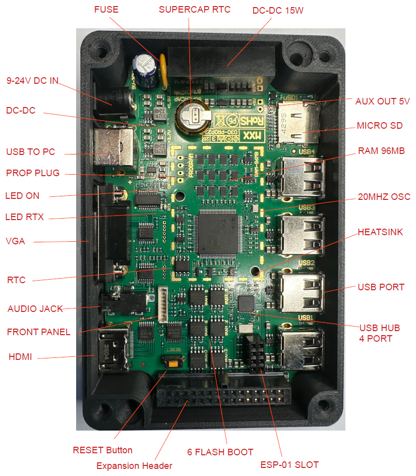
It briefly consists of:
- 96 MB RAM with 16bit Bus (previous 8 bit bus)
- USB port for programming and power supply (USB type B )
- Additional PROP PLUG header
- Additional 9 - 24 V power supply input (for 5V 15 W)
- Additional leds for power supply and rtx signal (previous rtx only)
- Front panel connector
- High precision RTC (supercap backed up)
- Selectable boot from 6 different flashes (previous 4 flashed)
- SD card high speed 4 wire bus (previous slow mode)
- USB hub 4 ports for joystick, keyboard and mouse (previous 2 ports)
- VGA connector
- Stereo Analog audio out (headphones or line)
- HDMI connector (previous not available)
- ESP-01 or ESP-01S connector (previous not available)
- Shared 16 bit expansion connector (previous not shared)
- ESD protection
- Optional dedicated heatsink Code 345-1744-ND (previous not available)
- 6 Layer PCB (previous 4 layer)
A major difference compared to previous PCB is about heat dissipation. The two additional layers increase heat transfer to external connectors (acting as heatsink).
I designed this board in an attempt to reduce the connections mess between P2 and the various peripherals typically used.
Furthermore, this board will make it easy to experiment with all those fantastic software related to the world of retro consoles and audio-video systems in general.
Special thanks to:
@rogloh
@evanh
@Rayman
@Wuerfel_21
@JonnyMac
@ersmith
@pik33
@cgracey
for the efforts put on the P2 platform, this board is based on and inspired by their work .
Another difference is the front panel which is now interchangeable with various options such as the 3.5" display and the 4.3" display which will be coming soon.
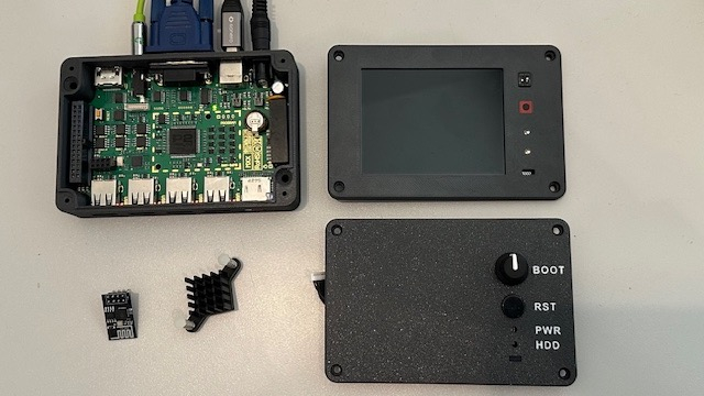
In the photo we can also see other accessories such as the heatsink and the ESP-01 module....
The LCD display is driven with 16 wires but in 24bit RGB configuration thanks to the help of latches so it does not require any initialization.

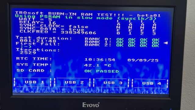
I also prepared a modified version of the Burn-in RAM test software created by Werfel_21 in order to quickly test the other peripherals on board.
Comments
Looks good!
Neat-o!") This is a very feature rich platform and looks like there's gonna be a lot of things in there to test as it's a big upgrade from before.
This is a very feature rich platform and looks like there's gonna be a lot of things in there to test as it's a big upgrade from before.
What do you have working so far? I see the front panel parallel LCD is already working in your youtube vid and it's responding quickly, and your test software screen looks useful. Any tricky problems you had to resolve or is it all coming up nicely?
I have one of these and can vouch for it as a great unit! If I've not given much feedback on it, it's because it's just been so good to me. (though I never tried messing with the RTC or the ESP module)
I've been using it as my main development system lately, it's just so nice and tidy. Did most of the work for MisoYume beta 11, P1 Classics Collection and this silly music thing on there. (and the Teapot demo on the previous version)
Maybe we can workshop, like, a catchy name for this capital-T Thing? I've just kinda been calling it the "MXX box" or something to that extent. (Because I need
Nice re-use of the RAM tester text driver thing!
(BTW, I think(?) the version of the FUNSCII font there has the full set of Parallax P1 ROM font PUA glyphs, so you can draw fully connected boxes if you want - you may need to add
--charset=oemto the compiler command line if not already there to get 8-bit extended characters, otherwise it will attempt to use UTF-8)Wow, Massimo, that is really nice. Congratulations.
But that's Massimo, Marco is @macca , you need to get your Italians straight.
OK, I need to get my Italians straight
@Wuerfel_21 Are your emulators going to work with this LCD?
IDK I don't have one or any specs. I think we talked about this once in some e-mails, but who knows what of that made it to the final product. (My influence did result in upgrading to 16 bit wide PSRAM)
Thanks again to everyone for the feedback!
Most of the hardware is tested and working as expected so far. One thing left to try is the fast 4 bit SD card interface, some help needed here.
The LCD panel responds quickly because it was inserted "hot" with the firmware already running...... also, perhaps by mistake, I compiled the demo with FlexProp that's why it's very fast (about 10x compared to propeller tool).
LCD test software is thanks to @Rayman, I only adapted the pasm LCD driver to fit my circuit.
No big issues in running the LCD panel as it's a raw 24 bit RGB parallel interface, (latched as 8 bit R / 8 bit G / 8 bit B to save some pins).
I would say PSRAM block was a bit tricky.
We used Marco yuotube account to post the video.
I'm going to share the schematics soon, it's something similar to the LCD 6 bit interface already present in NeoVGA but with 8 bits instead of six plus some syncing signals. Would be great to have the emulators running on the LCD but I really need help fo this.
Hope you can get the 24-bit latched LCD working with the emulators. Also have some dual latched boards here that can plug into eval/edge headers.
Think @Wuerfel_21 and myself decided that 16-bit with one latch was better at some point, but then just dropped the ball on it.
Think it was when realized could just use an hdmi panel for similar cost...
Oh carp! 🐟
I just realized the NeoYume you pre-loaded isn't using 4bit and when I build with that it doesn't work!
Uuhhh, I think that's a problem. I apologize profusely for forgetting to test it. (I was in a total rut for a few months...)
>
RBG latches cause ProblemsTM> I recall, was taling with Ray about a similar thing. The main problem is that when you build up the data bus gradually with latches, you'll very easily violate the hold timing constraints for the parts you latch first/last. But can't recall that now, need to troubleshoot that SD thing rather asap.
Lots of Italians to keep track of. Good to clear up any and all confusion.
Okay, so I've narrowed it down a bit:
The problem seems to be with the card power switch.
If I set the following config to disable it, SD4 is working:
But the expected problem of only being able to mount the card reliably on cold-boot appears. Launching any other program that puts the SD card into SPI mode needs a power or insert cycle afterwards.
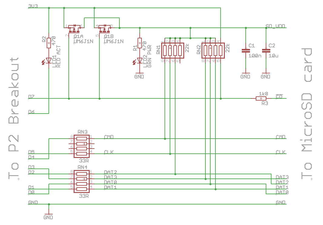
Relevant bit of schematic:

Building with -DSD_DEBUG begets us
Error: Stuck high at SD power-down.I think I see the problem! The actual power switch does work, but you've routed the pull-up resistors to VIO (pre-switch), but they must go to VDDSD (post-switch) instead. The driver tries to make sure the power is actually off by sampling the CLK pin with the P2's voltage comparator. This doesn't work if the pull-up is always high instead of being referenced to the SD power.
This is the correct setup as seen in the reference schematic:
Luckily this is a software issue that can be worked around! ( @evanh will try to kick me, I'm sure )
Go into
sdsd.c(included in NeoYume inblkdrvrdirectory) around line 242 and changeif( samples ) { #ifdef SD_DEBUG __builtin_printf(" Error: Stuck high at SD power-down\n"); #endif releasepins(); return 0; }to
    if( samples ) {
#ifdef SD_DEBUG
        __builtin_printf("  Warning: Stuck high at SD power-down\n");
#endif
        //releasepins();
        //return 0;
    }
(Then of course use the proper config with
SD4_PPWR = 23)EDIT: I've also pushed this nasty patch to the bundled SDSD driver to NeoYume's GitHub/SourceHut repos
EDIT2: fixed some wording
EDIT3: added ref. schematic
There's also another problem I noticed earlier, forgot about and just encountered again, I can't seem to flash large binaries properly. @MXX somehow got them on there, so I don't think it's impossible, but my loadp2 doesn't wanna, neither with the explicit flashloader or the new
-SPIoption. Need to check tomorrow if this is a general issue with all boards, I rarely use flash.What does help is enabling executable compression (
--compressflag to flexspin), which I am astonished I still haven't done by default everywhere.@Wuerfel_21 Think @ersmith said something about needing to switch to proploader for binaries?
Think just creating a fake .spin2 file with the binary in a dat section works usually though...
Correct. It is intended to comply with the SD spec of requiring a power cycle to be below 0.5 volts on VDDSD for at least 1.0 millisecond.
A software workaround for a hardware issue, thank you very much!
You're now relying on a 500 ms delay for the capacitors to discharge and just assuming it works without confirmation. The routine could be notably reduced in size ...
//-----------------------------------------------------------------------
// Simple power cycling of the SD Card, optional - if pin defined
//-----------------------------------------------------------------------

static int  sdcard_power( void )
{
    unsigned  PIN_CLK = clkpin;
    unsigned  PIN_CMD = cmdpin;
    unsigned  PIN_DAT = dat0pin | 3<<6;
    unsigned  PIN_PWR = pwrpin;    // pin number of power switch (-1 == not defined)
    uint32_t  samples, threshold;
    int32_t  tmr, timeout;

    releasepins();    // SD spec 6.4.2

    _pinl(PIN_CMD);
    _pinl(PIN_DAT);
    _waitus(1);
    _pinf(PIN_CMD);
    _pinf(PIN_DAT);
    _waitus(1);    // wait for pull-up resistors to act

    if( PIN_PWR == PIN_CLK ) {    // power switch not present
        if( _pinr(PIN_CMD) )
            if( _pinread(PIN_DAT) == 15 )
                return 1;    // pull-up resistors are present
#ifdef SD_DEBUG
        __builtin_printf(" Error: CMD/DAT pull-up resistors are missing\n");
#endif
        return 0;
    }

    if( _pinr(PIN_PWR) ) {    // An inserted card will pull this down against the 22k ohm pull-up
#ifdef SD_DEBUG
        __builtin_printf(" Error: SD Card not detected\n");
#endif
        return 0;
    }
#ifdef SD_DEBUG
    __builtin_printf(" Card detected ... 500 ms power cycle of SD card\n");
#endif

// Overpower the pull-ups so that the SD card can be powered down
    _pinl(PIN_CLK);
    _pinl(PIN_CMD);
    _pinl(PIN_DAT);
// Use blind 500 ms delay for SD supply to fall below the requisite 0.5 Volt
    _pinh(PIN_PWR);    // power off the SD card by overpowering the 1800 ohm Card Detect
    _waitms(500);

    releasepins();    // and power back on
    _waitms(1);

    return 1;
}
EDIT: Added the 1 ms power up delay too.
EDIT2: Added overpowering of the pull-ups
It is still problematic. The whole power cycling sequence still may not be working because all those pull-ups will be supplying power to the SD card.
You'll need to get a scope on the SDVDD power rail to see what is really happening.
EDIT: I've changed the routine above to hopefully drain the capacitor by overpowering all the pull-up resistors. I guess it's not too different to the original sequence since most of the pull-ups were driven low there too. Just the CLK pin extra now.
I've updated the releasepins() function too. Placed the power switch release at the end instead of beginning.
//----------------------------------------------------------------------- // Orderly clean up of pin and smartpin modes //----------------------------------------------------------------------- static void releasepins( void ) { unsigned PIN_CLK = clkpin; unsigned PIN_CMD = cmdpin; unsigned PIN_DAT = dat0pin | 3<<6; unsigned PIN_PWR = pwrpin; unsigned PIN_LED = ledpin >> 8; // Doubles up as SDSC byte addressing flag in bit0 _pinf(PIN_CLK); // stop SD clock _pinf(PIN_CMD); _pinf(PIN_DAT); _wrpin(PIN_CMD, 0); _wrpin(PIN_DAT, 0); _waitus(1); // wait for pull-up resistors to act _wrpin(PIN_CLK, 0); // release clock pin if( PIN_LED != PIN_CLK ) { // activity LED is present _pinf(PIN_LED); _wrpin(PIN_LED, 0); } if( PIN_PWR != PIN_CLK ) { // power switch is present _pinf(PIN_PWR); _wrpin(PIN_PWR, 0); } _waitus(1); // wait for pull-up to act }That's why I'm keeping the crappy patch for now. I'd hope this can be fixed in future board revs.
Good boards can enjoy not having to wait the full 500ms timeout.
Though If you think you have a nicer version, feel free to post it as a whole sdsd.c
Hard ask because the whole thing has no test points (see photos in top post)
Thanks @Wuerfel_21 and @evanh for trobleshooting this SD issue, meanwhile we found 2 things:
I made a crappy patch on the board to move the pullups after the switch, a quite easy task hopefully.
Now 4 bit SD driver is working and is blazing fast! (see video, 700 MB in 5s, impressing)
I checked with scope before the modification and in fact the SDVDD signal was not dropping low enogh (probably due to pullups always high).
This is the patch one trace cut and a wire added
The next board revision will include this fix for sure.
Tidy fix, good to see!
Thanks for posting the scope screenshot too. Good to see how bad it was.
You're right. Having two routines just makes it even bigger.
I probably could throw away the voltage rising check though. It is entirely extra code and since once the power is back on it charges the caps much more predictably than the discharging.
Okay, so I've adopted making that error into a warning that doesn't fail. And removed the subsequent power up level check.
PS: It's untested as a warning. Massimo, if you've still got a board that can trigger the warning then that'd be great to verify on.
PPS: It's roughly tested now - Using an adaptor without a power switch. I told it the power switch existed and added a pull-down resistor to get passed the card-detect check.
That 700 is in MBits not MBytes by the way. So it's transferring all that game data at an average rate of ~17.5MByte/s. I think @evanh's raw code can actually go faster now but there's always other overheads and delays involved. Maybe some fragmentation of the filesystem or the overall rate is being constrained by NeoYume's processing or clock requirements.
Default clock divider also is sysclock/4. It can be runtime set to use /3 or /2 using an ioctl() call. Data writes aren't effective beyond sysclock/3 because the concurrent CRC calculating takes that many clock ticks for each written block but data reads can approach sysclock/2 speeds by also turning off the read CRC checking - Another ioctl().
So, yep, I've successfully doubled that speed during tests previously.
You can see that the big graphics data ("Type 6",
LOAD_CROM) is much slower to load than the other data. This is because it has to read from 2 files and interleave the data. This means it's reading disjoint 16K blocks instead of a nice contiguous file. The interleave code also probably becomes significant at that point. See also: https://git.sr.ht/~wuerfel_21/NeoYume/tree/master/item/neoyume_upper.spin2#L442 (I think the code is fairly optimized, but those block reads might still have some wiggle room for optimizing stall cycles)Oh, multiple open files is something I never compared when I added the lazy CMD12. All testing has been one file at a time ...
Thanks, I've succesfully tested on an unpatched board and it works!
@ersmith I had to use loadp2 version 0.072 (Jun 10 2024, from flexspin 6.9.9 package), at some point loadp2 stopped woking with more recent flexspin versions.
I think my previous bundled SDSD was really old, but a quick test seems to indicate everything still works with the new 1.7 dropped in as-is. I pushed that to both git remotes.
Yeah it's just like that.
To elaborate what happens in that code I linked (from memory, maybe an error there):
The way they're stored in the ROM dumps is incredibly cursed:
The code I wrote loads a 16K chunk of both files, then processes it into a 32K interleaved buffer
This all is basically an artifact of MAME being the most popular arcade emulator and its developers like using raw ROM dumps (like you'd get from pulling the chips and reading them out), so that just became the de-facto format for NeoGeo ROMs.
Interesting. I use Linux and you use Windows, right? Strange that issues happen with both, but also that regular RAM loading works regardless, it's only flashing that fails.
Also BTW I gave the Live Forum guys a quick look at my Thing and they all want one now :P