

ServoSpy: tuning without PC software
 ManAtWork
Posts: 2,355
ManAtWork
Posts: 2,355
I just started another small hardware project with the P2. I have to tune the control loops of Chinese servo drives. The cheaper ones don't support autotuning and there is often no PC software provided. Or if it is it's only in Chinese language and the manuals are really poor.
But fortunatelly, for the P2 it's no big deal to simply tap the Step/Dir command signals and the encoder cable. The idea is to compare both position values and provide some sort of scope display of nominal vs. actual velocity and following error.
Step/Dir is simple, there's a smart pin mode for this (%01101 = P_REG_UP_DOWN). The absolute encoder signal is a bit more tricky but not really hard to hack. I found out that the magnetic 23-bit absolute encoders use the same protocol as some older optical encoders from Tamagawa Seiki I already knew. It's called "SmartAbs" and uses a 2.5MBd serial communication via an RS485 line.
CON
  _xtlfreq = 25_000_000         ' KISS board Xtal
  _clkfreq = 200_000_000        ' clock frequency

  pinDp     = 33  ' RS485 D+
  pinDm     = 32  ' RS485 D-
  pinOut    = 31  ' Test output

  pinStep   = 41  ' Step input
  pinDir    = 40  ' Dir input


VAR
  byte  rxCog
  long  stepCmd

OBJ

PUB main ()
  wrpin (pinDir, P_SCHMITT_A)
  pinstart (pinStep, P_REG_UP_DOWN + P_MINUS1_B + P_SCHMITT_A, 0, 0)
  rxCog:= coginit (NEWCOG, @StartRx, @dataRq)
  repeat
    eofSig:= 1
    repeat while eofSig>0
    stepCmd:= rdpin (pinStep)
    debug (UHEX_BYTE_ARRAY (@dataRq, 7), UHEX_LONG (encPos), UHEX_LONG (stepCmd))
    waitms (100)

DAT
' SmartAbs Encoder Data transmitted over RS485 line @2.5MBd
' See Tamagawa Seiki docs for TS5700N8501 (17 bit or 23 bit)
dataRq        byte 0      ' request byte
dataCf        byte 0      ' control field
dataSf        byte 0      ' status field
dataDf        byte 0,0,0  ' position data
dataCrc       byte 0      ' CRC field
eofSig        byte 0      ' end of frame signal
encPos        long 0

DAT
  ORG
StartRx       fltl   #pinDp        ' reset smart pin
              wrpin  ModeRx,#pinDp ' async serial RX
              wxpin  BaudRx,#pinDp ' 2.5MBd 8N1
              drvl   #pinDp

newFrame      mov    rxCnt,#7
              mov    ptrb,ptra
newByte       mov    time,Timeout ' timeout 50us
waitRx        testp  #pinDp wc
        if_nc djnz   time,#waitRx
        if_nc jmp    #newFrame    ' if timeout -> start over
              rdpin  rx,#pinDp
              shr    rx,#24
              rolbyte newPos,rx,#0
              wrbyte rx,ptrb++    ' write byte to buffer
              djnz   rxCnt,#newByte
              movbyts newPos,#%00011011
              shl    newPos,#9    ' 23 bits -> 32 bits left justified
              sub    newPos,oldPos
              add    oldPos,newPos
              sar    newPos,#9
              add    pos,newPos   ' handle rollover/multi-turn
              wrlong pos,ptra[2]  ' write 32 bit position
              wrbyte #0,ptra[7]   ' write EOF flag

dropByte      mov    time,Timeout ' timeout 50us
waitGap       testp  #pinDp wc
        if_nc djnz   time,#waitGap
        if_nc jmp    #newFrame
              rdpin  rx,#pinDp    ' ignore more bytes until inter-frame gap
              jmp    #dropByte


ModeRx  long  P_ASYNC_RX + P_MINUS1_B + P_COMPARE_AB
BaudRx  long  80<<16 + 7 ' 2.5MBd 8N1
Timeout long  200*50/8 ' timeout 50us
oldPos  long  0
pos     long  0

rxCnt   RES 1
rx      RES 1
time    RES 1
newPos  RES 1
This little program can at least display the nominal and actual position. The next challange is to do proper scaling and offset correction. The servo uses some sort of so called "electronic gear" to scale 10,000 step pulses per revolution to 2^23 encoder counts.
Comments
@ManAtWork
I have been looking at the Chinese drives and might be about to pull the trigger on a couple; a 2KW and a 4.5KW.
I see that they are available with analogue input which is what I prefer and they have a simulated encoder output.
What I am aiming for is to simplify everything. A servo-drive, configured for "torque mode" (current command) requires minimal setup, literally a transconductance and commutating module.
I prefer to handle everything else on the P2 but I'm curious about why you are going with pulse & direction?
Craig
The step+dir signals have historical reasons. I had and still have a lot of customers who use stepper motors or want to use their own drives. Another reason is simplicity. I don't need (simulated incremental) encoder signals.
Be careful, not all Chinese drives support them. I think, the dirt cheap ones from HLTNC and PFDE don't. Those from JMC and Lichuan do.
I don't know how many times in my life I have programmed some sort of bresenham interpolator or electronic gear. They all work very similar but according to murphy there is always at least one reason why I can't use one of the existing implementations. This time it needs to be 64 bits and signed. After the usual mistakes of taking the wrong register or forgetting to set the right flag it finally works.
 ")
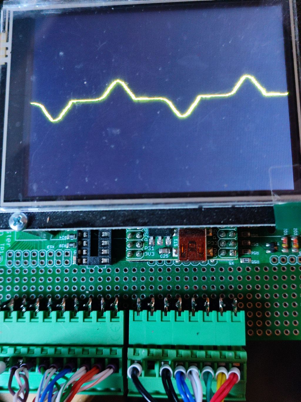
'' Servo Spy: Servo tuning by comparing nominal vs. actual position
'' Monitor Step/Dir command and absolute encoder serial data communication

' bene 16-Aug-2025 first test
' bene 18-Aug-2025 + scope window


CON
  _xtlfreq = 25_000_000         ' KISS board Xtal
  _clkfreq = 200_000_000        ' clock frequency

  pinDp     = 33  ' RS485 D+
  pinDm     = 32  ' RS485 D-
  pinOut    = 31  ' Test output

  pinStep   = 41  ' Step input
  pinDir    = 40  ' Dir input

VAR
  byte  rxCog
  long  stepCmd
  long  encOffs
  long  lastPos

OBJ

PUB main () | np, ap, la, ln
  wrpin (pinDir, P_SCHMITT_A + P_INVERT_IN)
  pinstart (pinStep, P_REG_UP_DOWN + P_MINUS1_B + P_SCHMITT_A, 0, 0)
  rxCog:= coginit (NEWCOG, @StartRx, @dataRq)
  encOffs:= GetEncPos ()
  la:= GetEncPos ()
  ln:= 0
  debug (`SCOPE Motion SIZE 500 330 SAMPLES 500)
  debug (`Motion 'NomVel' -1000 1_000 300 10 15 GREEN)
  debug (`Motion 'ActVel' -1000 1_000 300 10 15 YELLOW)
  debug (`Motion 'PosErr' -1000 1_000 300 10 15 RED)
  debug (`Motion TRIGGER 0 -5 5 350)
  repeat
    np:= stepCmd:= rdpin (pinStep)
    ap:= GetEncPos ()
    'debug (UHEX_BYTE_ARRAY (@dataRq, 7), UHEX_LONG (GetEncPos ()), UHEX_LONG (stepCmd))
    debug (`Motion `(np-ln, ap-la, np-ap))
    la:= ap
    ln:= np
    waitms (10)

PRI GetEncPos (): p
  eofSig:= 1
  repeat while eofSig>0
  return encPos - encOffs


DAT
' SmartAbs Encoder Data transmitted over RS485 line @2.5MBd
' See Tamagawa Seiki docs for TS5700N8501 (17 bit or 23 bit)
dataRq        byte 0      ' request byte
dataCf        byte 0      ' control field
dataSf        byte 0      ' status field
dataDf        byte 0,0,0  ' position data
dataCrc       byte 0      ' CRC field
eofSig        byte 0      ' end of frame signal
encPos        long 0

DAT
  ORG
StartRx       fltl   #pinDp        ' reset smart pin
              wrpin  ModeRx,#pinDp ' async serial RX
              wxpin  BaudRx,#pinDp ' 2.5MBd 8N1
              drvl   #pinDp

newFrame      mov    rxCnt,#7
              mov    ptrb,ptra
newByte       mov    time,Timeout ' timeout 50us
waitRx        testp  #pinDp wc
        if_nc djnz   time,#waitRx
        if_nc jmp    #newFrame    ' if timeout -> start over
              rdpin  rx,#pinDp
              shr    rx,#24
              rolbyte newPos,rx,#0
              wrbyte rx,ptrb++    ' write byte to buffer
              djnz   rxCnt,#newByte
              movbyts newPos,#%00011011
              shl    newPos,#9     ' 23 bits -> 32 bits left justified
              sub    newPos,oldPos
              add    oldPos,newPos ' handle rollover/multi-turn
              sar    newPos,#9     ' right justified 23 bits
              abs    x,newPos wc
              qmul   x,GearMul
              testb  rem,#31 xorc
              modz   _C wz         ' Z = signs of rem and newPos differ
              abs    rem
              getqx  x
              getqy  y
        if_nz add    x,rem wc
        if_nz addsx  y,#0  wc
        if_z  sub    x,rem wc      ' add/sub remainder
        if_z  subsx  y,#0  wc
        if_c  add    x,GearDiv     ' if YX<0 then YX+=GearMul..
        if_c  mov    y,#0

              setq   y
              qdiv   x,GearDiv
              getqx  x
              getqy  rem
        if_c  sub    x,#1          ' ...and result-=1
              abs    y,newPos wc
              negc   rem           ' set sign of remainder
              sumc   pos,x
              wrlong pos,ptra[2]  ' write 32 bit position
              wrbyte #0,ptra[7]   ' write EOF flag

dropByte      mov    time,Timeout ' timeout 50us
waitGap       testp  #pinDp wc
        if_nc djnz   time,#waitGap
        if_nc jmp    #newFrame
              rdpin  rx,#pinDp    ' ignore more bytes until inter-frame gap
              jmp    #dropByte


ModeRx  long  P_ASYNC_RX + P_MINUS1_B + P_COMPARE_AB
BaudRx  long  80<<16 + 7 ' 2.5MBd 8N1
Timeout long  200*50/8   ' timeout 50us
GearMul long  625        ' 10_000 / 2^23
GearDiv long  524288

oldPos  long  0
pos     long  0
rem     long  0

rxCnt   RES 1
rx      RES 1
time    RES 1
newPos  RES 1
x       RES 1
y       RES 1
The servo repeatedly moves forth and back by 10mm with this little NC program.
The tuning is terrible (default factory settings) and the following error is more than 0.5mm (1000 steps = 1mm). But with this little tool I hopefully can improve it in a convenient way, soon. While the NC program runs in the background I can simply move the feed override slider to adjust the speed, set parameters over the MODBUS and watch the results in realtime.
Of course, for the promise in the title "without PC software" to be true the scope traces have to be dispayed on the P2 board instead of the PC screen.
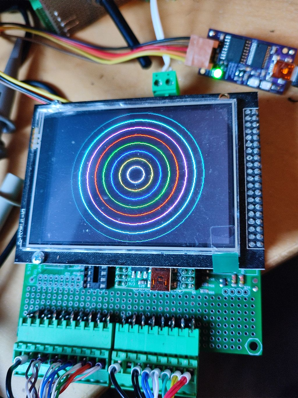
The plan is to use this little board with a KISS module and an LCS screen.
It works!") But drawing the lines with the standard IL9341 LCD driver is way too slow. I need to draw to a RAM buffer, first, and then copy the bitmap data to the screen at once.
But drawing the lines with the standard IL9341 LCD driver is way too slow. I need to draw to a RAM buffer, first, and then copy the bitmap data to the screen at once.
I send via Bluetooth to an Android device: