

Towards a P2 controlled Embroidery Machine?
 Christof Eb.
Posts: 1,539
Christof Eb.
Posts: 1,539
Hi,
for some time I have been wondering, if I should try an embroidery machine. This should not be extremely difficult, I think. You need a sewing machine, some electronics to start and stop it, and an XY-table plus some sort of synchronising, because you need to move the table only when the needle is up. Actually you can find some fine projects in the net.
Like: https://lordovervolt.com/embroidery
So it's possible to do it.
At the moment I am at some brainstorming stage and I have not yet decided to really do it. (Only thing is, that I learned, that I have to start earlier than last year, if I want to make Christmas presents....)
Has anyone here tried this?
Comments, suggestions?
Christof
Comments
Seems to be a good idea, to look at the entire CAD/CAM chain. There are some tools available: https://inkstitch.org/
Machine has to be able to process the output format of inkstitch.
Hm, these existing concepts all use linear movements. But as the needle is round, orientation is not important. And support of the vertical axis is given by the sewing machine. So I am thinking about two rotating axis like a robot arm holding the frame. Frame shall be 180mmx180mm. This area lies in a circle of diameter 255mm.
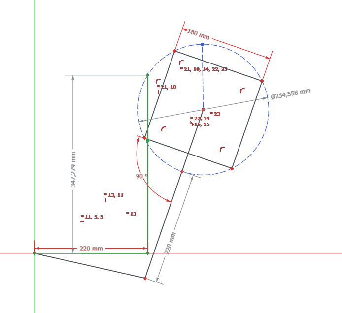
Length of 220mm for each lower and upper arm should be sufficient.
Movement shall be done with a step motor and a belt drive for each axis.
Thanks to P2's cordic, conversion of coordinates should be easy?
[citation needed]
I think you might get a kinda funky radial pattern to the stitches from moving like that?
Certainly interesting idea. Real embroidery machines are really expensive.
There seems to be some misunderstanding here. For embroidery only the position of the stitch is important. Way of movement between stitches have no importance. So if coordinates are converted properly, there should be no "funky pattern". The relative rotation of the needle between two stiches will be small. There are 2 degrees of freedom here: A shoulder joint and an elbow joint. Together they give X+Y. Perhaps this picture is better:
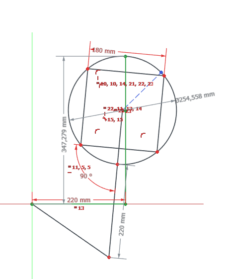
Green lines give position of needle to shoulder.
Will it be a "real" embroidery machine? Yes, I hope so. :-) Of course it can do only one colour at a time.... The expensive part is the sewing machine.
Depending on arm length and gear ratio I hope to chieve 0,2mm resolution. The big gear is to be printed ABS. 240 teeth. Linear axis would give higher resolution.
What i meant is don't think the direction of the stitch is entirely immaterial, though IDK to what extent we'd care.
(I know about manual embroidery and machine sewing, but I never did machine embroidery....)
Hm, I cannot imagine that the Direction of the needle has importance, because when the needle has left the hole, the thread can move freely. (Edit: Though the other thread will hinder this.) Also for the length of a stitch of perhaps 5mm, the angle of misalignement will perhaps be 3 degrees.
I think, I will risk this.
But thanks for the input, there is much to learn here for me. Which is part of the fun, of course.
With rotating axes it looks, if I only need to buy very few parts. And I can use the same printed parts twice.
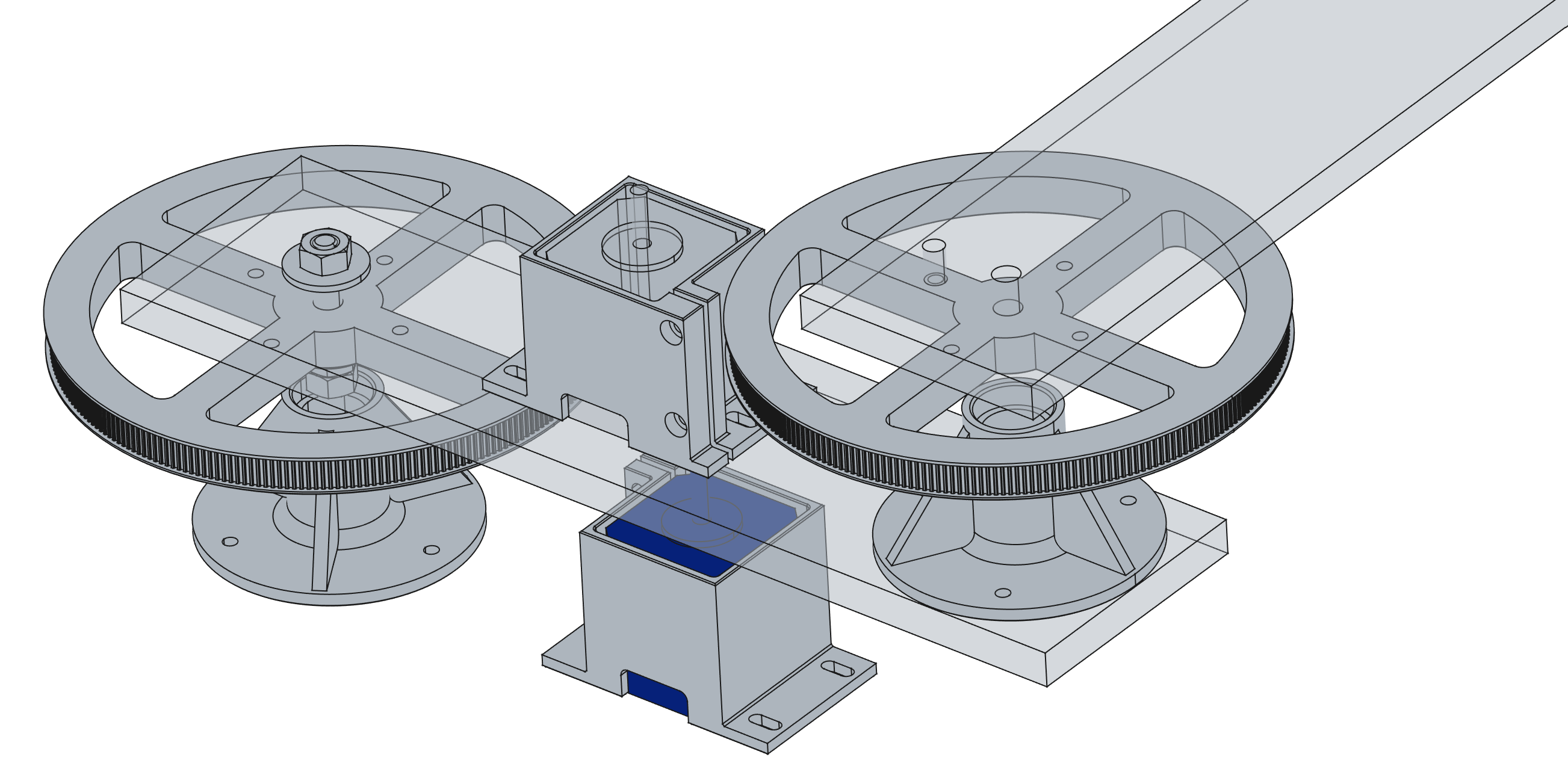
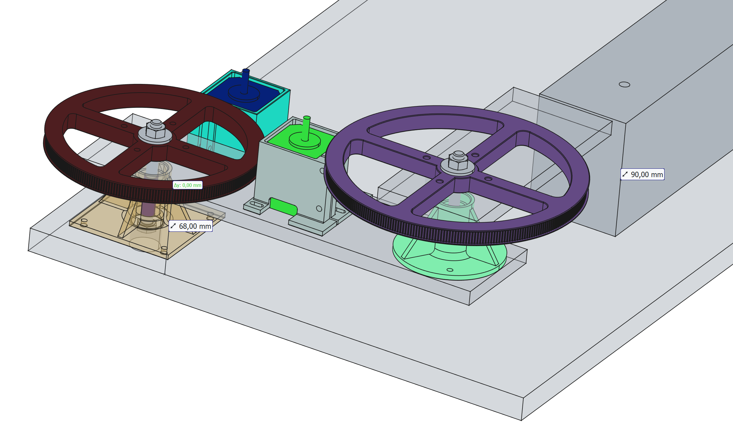
The design changed a little bit mainly to get the right hight and no, I was not able to use identical parts twice. Good News: The printed wheels do fit to the timing belt. :-)
There was a "funny" finding though: I had used a free internet calculator to get the centre distance for a given length 610mm of the belt. When the belt arrived and I tried to mount, the real centre distance was about 160mm instead of calculated 128mm!
So to keep the length of the arm I made a new wheel for the upper arm with 288 teeth instead of 240. I also found a better calculator..... Never trust anything on the net....
Some effort was put into the bearing units to make them precise. They each use two 8x22x7 608ZZ ball bearings, which you can buy easily because they are used for skaters. The axle is a bolt M8x80. As it's shaft diameter is too small, I used some adhesive tape to increase the diameter. Also the bearing chair has a press fit. There is a sleeve between the bearings on the bolt, so one nut can hold everything together.
The block on the right side of the picture indicates the sewing bed of the machine, which has a height of 90mm. The circle is the needle position.
So now the next steps will be to try to control the sewing machine.
This is a very nicely built Bernina 810, which is almost 50 years old but in very good condition. This machine is fully mechanic. I do not want to wreck it and I do want to be able to reconvert it to it's original form. It comes with a very special Y-cable (for the pedal) with special connectors.
Unfortunately I did not find proper schematics, but I have opened the starter pedal and it contains a series of resistors, which are shunted one by one, if you press the pedal. It starts at 700Ohms. There is also a "slow" switch at the machine itself, no idea how this works. Machine is rated 100W.
At the moment I plan to try first a solid state relay only to switch on and off with a fixed position of the pedal. That relay is based on 1565E module with zero cross start. I have found some schematics for more sophisticated controllers with high voltage MosFet PWM, but I am not sure.
For synchronisation I have ordered some AS5600 magnetic position encoders. Idea is to fix the magnet on the centre of the hand wheel. We need the machine to be able to stop, when the needle is up and after the thread is tightened. And also we need the frame only to move, when the needle is up. I hope that the AS5600 will give sufficient information. It should be much better than a mark at the outer diameter of the handwheel for a reflex light sensor. I have read, that it gives a practical resolution of 2 from 360 degrees. The user must fix the handwheel clutch at the right position.
Next difficult question will be, if I use Taqoz, which has everything, that is needed, or if I use P2XCForth, where I must develop tool and application at the same time....
Christof
If someone is wondering, what is the goal: https://ia800708.us.archive.org/2/items/singerinstructio00sing/singerinstructio00sing.pdf

You always wanted to have that on your shopping bag! It's from 1911. I wonder how they did the colour printing from a photo then?
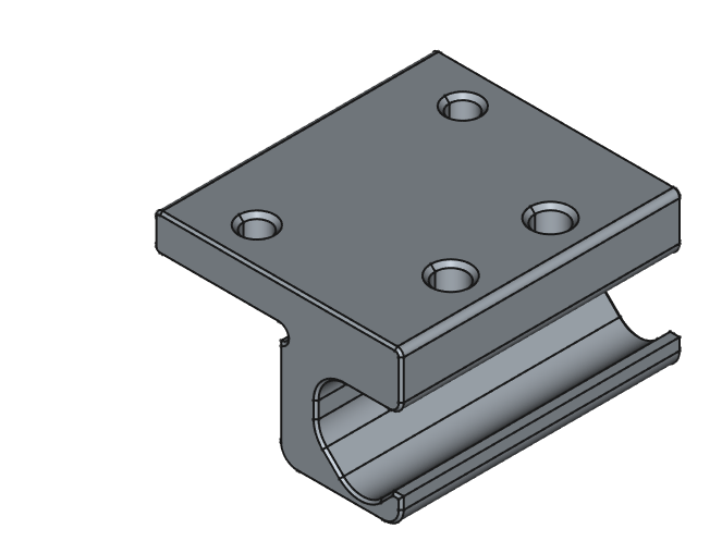
As5600 magnetic encoders have arrived and I was able to get a voltage with my Multimeter. I think, this is a very interesting item for such projects. Designed a sensor holder.
I can switch on and off the motor of the sewing machine with the solid state relay. Acceleration is probably too high with this setup.
Magnet and sensor in position. Centricity has to be well aligned to get a proper signal.
( @Rayman perhaps this sort of encoder might be helpful for your balancing robot to overcome play? There are some similar ones AS5048 with even 14 bits resolution. )
Ordered some module, that can control a TRIAC via isolated 1...500Hz PWM signal for the motor. The problem is, that the motor must be controlled around perhaps 1/10th of it's full speed. The load seems to vary quite a lot during one stitch.
Also ordered some 500Ohms, 50W resistors as a second option.
While I am waiting for the new pwm controller, I was able to calculate speed from the magnetic encoder. Using the voltage output. Had decided to use P2XCForth. Nice to be able to use code from obex. Thanks to @evanh for adc sar! Also to @JonnyMac for pwm!
Also got some crude speed control working.
Funny, when I was googling about motor control for a universal motor, a good hit was the very first schematic in https:///discussion/164638/controlling-ac-universal-motor-blower-with-a-propeller/p1
This circuit limits speed due to back emv.
As control of speed turns out to be rather difficult, I am wondering about the allowed timing window to move the fabric.
When the needle goes up and has left the fabric, there is a phase, when the yarn is pulled tight. This completes the stitch.
Of course when the needle enters the fabric, we need to be at the stable correct position. But when can we start to move?
At the risk of explaining the obvious, just watch when in the cycle the feed dogs come up. I would assume they're designed to use the broadest time window available to make the movement smoother?
Aaahhh So you can't stop the machine at a defined needle position....
There is good news and bad news with the pwm triac module.
Good news is that with it we can control motor speed and dim the sewing light accordingly. Bad news is that it has a big latency. It seems to update only once a second or so.
So it looks as if I will have to use one cog to directly control an isolated triac synchronised to mains. Or experiment with some resistors.
Yes, good idea to watch normal sewing operation.

Diagram shows rotation of handwheel counter clock wise.
Outer ring: Needle enters fabric at 0 and leaves it 193 degrees. Top position of needle is at 294 degrees, lowest position is 145 degrees.
Middle ring: Thread puller begins pulling at 244 and ends pulling at 348
Inner ring: Mover (feed dogs) begin at 255 and end at 356, just before needle re-enters fabric.
So both pulling and movement of fabric happen at the same time and not immediately, when the needle has left the fabric.
The universal motor can now be controlled via a RobotDyn Dimmer Module, as described here: https://forums.parallax.com/discussion/comment/1568487#Comment_1568487
It is still rather difficult to control the motor speed though.
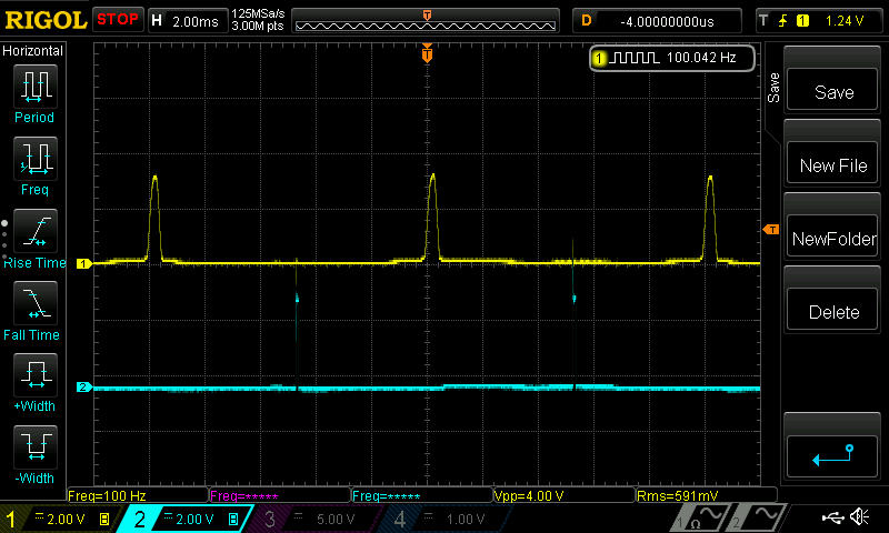
The triac trigger (blue) is about in the middle of the zero-crosses (yellow) when the sewing machine is at that tiny spot between stopping due to friction and starting to gallop.
Also I now learned, that the magnetic position signal is disturbed, when you connect the machine to mains. Some grounding of the machine seems to lessen this.
Ha!")
Got slow speed control running! Better centre alignment of the magnet, averaging magnet position, grounding the machine housing, a control loop at every mains cycle (100Hz) and a large P- factor does the trick. :-)
Speed is not completely even but it will be possible to stop at a useful window around needle top.
Machine hums and groans heavily.
Edit: yes, single stitch is possible now.
cool!
Today seems to be the day, when things fall into place. (???)
Was able to port the stepper code from my EggBot and it is now possible to move the arms. Not yet with coordinate transformation. And just constant speed.
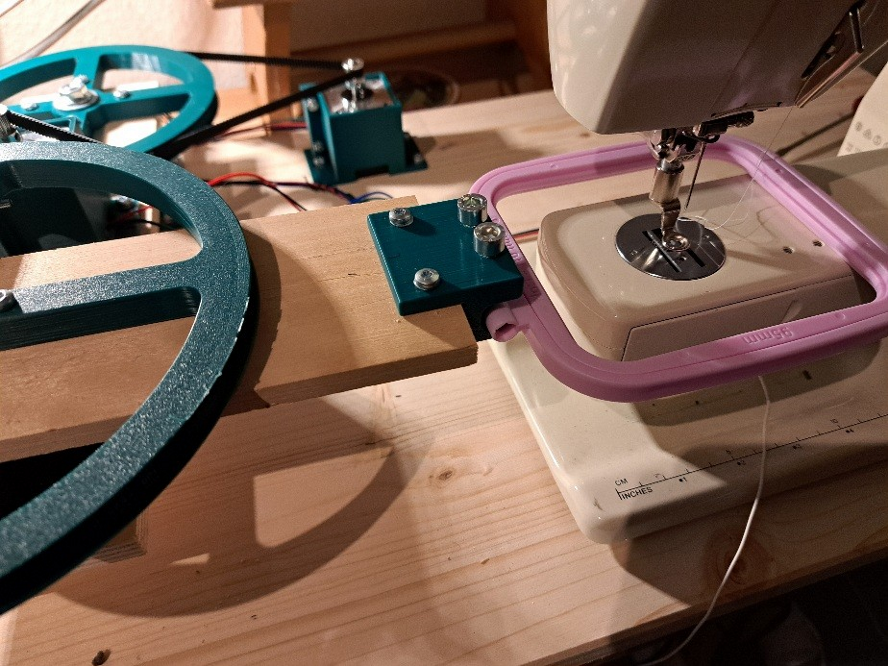
Adaption of the frame to the arm was simpler than thought. There are 2 M6 bolts in threaded bores to clamp the frame. I had bought a set of 3 frames of different size. This is medium.
We will see, if we can do some first stitches tomorrow?
Oh oh oh, finish of "things fall into their places".
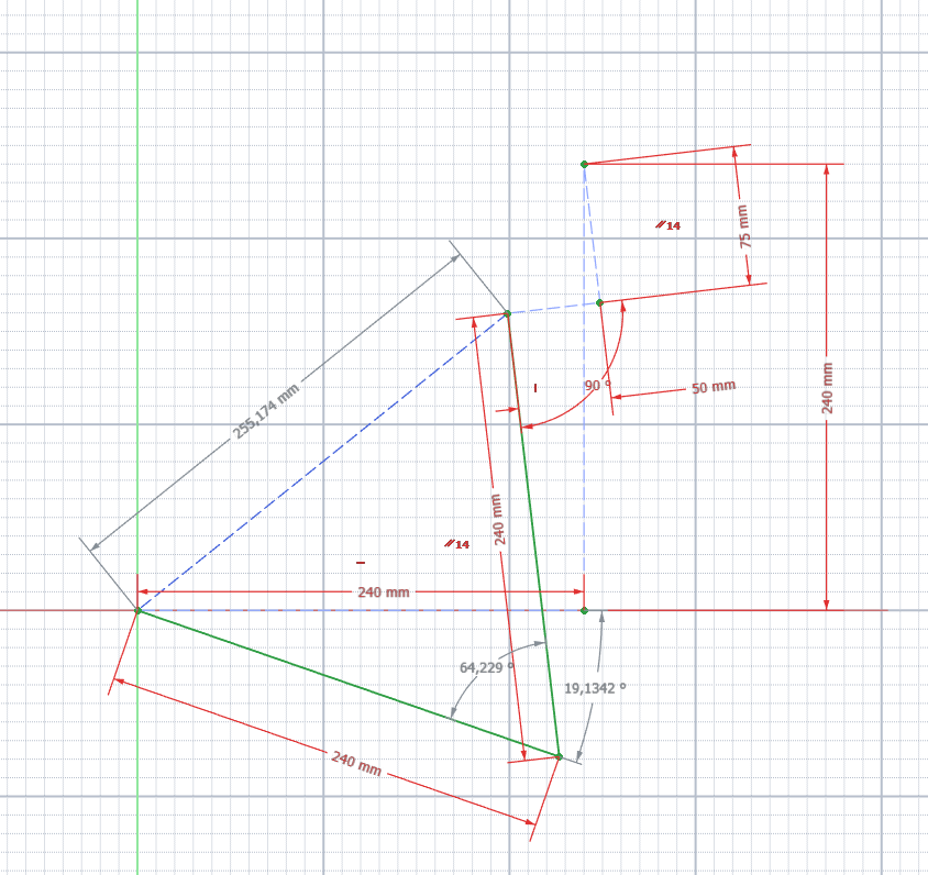
I have now begun to do the coordinate transformation. While Freecad can solve this easily, the solution for P2 "is not obvious to me". (To say the least.)
Given: X=50, Y=75 and the geometry
Wanted: The two angles Wu=19,13° and Wo=64,23°
The keyword there is "Inverse Kinematics"
Thanks for the correct wording, this is often helpful.
I already had some idea how to use the rules of cosines here. But I then realised, that my original coordinates X Y are also rotating. These give an offset to the wrist.
Forward calculation with given angles seems simpler.
Perhaps I will try some 2 dimensional iteration or some sort of interpolation in a 2 dimensional table.
Edit after some sleep: Well at least the study of https://de.wikipedia.org/wiki/Inverse_Kinematik brought, that it is not a trivial problem. I also think, I have some strategy, perhaps not the most efficient but hopefully doable: I will try iteration using 2 times cordic rotations for the forward calculation.
Ha, forward calculation and iteration works, needs about 60 ms for 120 Iterations.
")
Thanks to cordic rotation by P2 hardware!
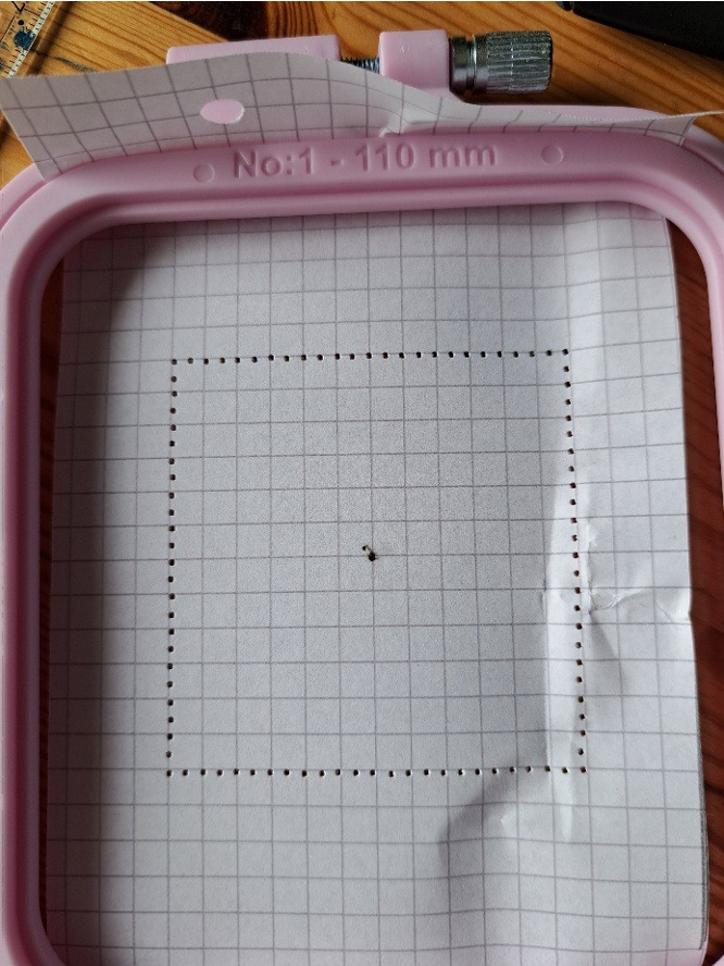
This is a 60x60mm square with 2,5mm stitches, done as one program. The paper grid is quite accurate.
Why is one iteration taking you 500µs, that seems slightly excessive?
Hi,
There is a whole bunch of things, that can be done, to make it faster.
It's done in Forth. So shifting it to C would help a lot.
It uses a lot of words, which are implemented using the trap mechanism. I have not yet dared to use the new absolute address operator to call a function. A few more words could be implemented in the xbyte machine.
Probably the number of iterations can be optimised also.
On the other hand I am quite glad, that the approach works at all, as I was standing before Inverse Kinematics "wie der Ochs vorm Berg". 60 ms is no killer.
I am curious, how precision will be with real stitches with thread. The whole mechanical concept is still not really proven.....
Edit: Due to better starting point and faster narrow down, I got the number of iterations reduced to about 35 and 17ms. Even with better accuracy due to better scaling. :-)
Well, perhaps the prove of concept is there") :
:
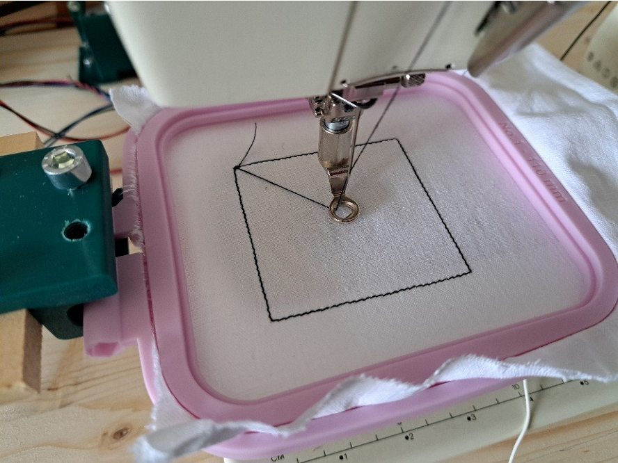
Stitch length reduced to 2.0 mm. 60x60mm square. Speed without any optimization is 1400ms per stitch. So around 42 stitches per minute. At the moment this is good, as we want to watch it. Well, a top notch Brother 880E (~ 1500 €) can do up to 850 stitches per minute....
Back from summer break and resumed project.")
Added a state machine for a single stitch to cog 2, which controls the triac for the sewing motor.
Also added speed ramping for the steppers and assigned cog 3 to control the movement of the fabric. Cog 0 does the coordination. So coordinate conversion can now be precalculated by cog 0 and the movement of the fabric can then start during the vertical upward movement of the needle.
Also I did some measurements and learned some things:
1. When the yarn is pulled, then an additional yarn break is activated. This is no problem for small movements like normal sewing stitches but it is not good to do large movements, so it is better to start movement before.
2. The sewing machine has a light bulb lamp. As in my setup the whole machine is controlled by the triac, this light bulb is in parallel to the sewing motor and sees the same voltage. It is very effective as a break-resistor and helps a lot to tame the dynamics of the drive of the sewing machine. - I do not really understand, what happens to the magnetic field, when the triac is off, because the field winding of the motor then is also switched off. In any case the back emv voltage seems still be to be generated. The light bulb will also act as a massive snubber.
A cycle is 0...2550 angle units of the handwheel.
0 needle enters fabric
1200 needle leaves fabric
1350 start of stepper fabric movement, next stitch will be only scheduled, after this positioning is completed
(1550 start of yarn pulling)
1800 if next stitch not pending then stop needle motor else continue directly with this next stitch
(1930...2110 machine will come to halt, if switched off at 1800)
All in all the sewing motor is now running through without stops for the stitch length of 2mm when the test square is done and we can now achieve a stitch in about 600ms average, 100 stitches per minute.
Probably it's time to find out, what is needed to process inkstitch output....
That is intended to be a smiley... (Well, I never liked these drawing programs. Will have to get better....) But you can draw something with Inkscape and the InkStitch plugin can convert it to embroidery stitches. In this case zigzag.
The result can be saved in several formats. Among them is GCODE and also HPGL. I always liked HPGL. It is simple and powerful and does only need integers. Resolution here is 0.025 mm. Seems to be fixed.
There are only 3 commands necessary for the interpreter to unterstand:
PU - goto xy
PD - goto xy and make one stitch
EN - end interpreter
I don't know, if SPx is additionally used for color change here?
Each line starts with two chars, which represent the command. X and Y a separated by a comma. They use LF for line ends. Smiley has 223 lines for 220 movements and 2530 bytes length.
Sometimes imperfection is more fun....
So the hpgl-interpreter works. It is only 62 lines.
This is upscaled x2 from the 10x10mm hpgl to 20x20mm, my second trial. I think, the resolution of 1/40 mm is not the reason of all that jitter.
It would be good to have some direct comparison with a bought embroidery machine.
Nice thing is, that Inkstitch automatically adds stitches to fasten the yarn. You can just cut the thread. (I don't know the correct translation of "vernähen").
Trying to improve resolution: Lowered tolerance for coordinate transformation, increased stepper motor current. Both seemed to help a bit.
And ordered steppers Nema17 42x46 with 0,9degrees or 400 steps per revolution.
Half step resolution will then be doubled.