

Smartpin pulse and direction
 Mickster
Posts: 2,908
Mickster
Posts: 2,908
' --- Constants ---
CONST _clkfreq = 300_000_000 ' Your P2's system clock frequency
CONST MY_PULSE_PIN = 10      ' Pin for pulse input (direction pin will be MY_PULSE_PIN + 1)

' --- Main Program ---
SUB MAIN()
    DIM pd_count AS LONG ' Variable to store the pulse/direction count

    ' --- Configure Pulse & Direction Counter ---
    ' pinstart(pulse_pin, PINTYPE_config, PINTRA_value, PINTRB_value)
    '
    ' PINTYPE_config:
    '   P_REG_UP_DOWN: The correct mode for Pulse/Direction counting in your FlexProp environment.
    '   P_SCHMITT_A: Enables Schmitt trigger input on both pulse and direction pins for noise immunity.
    '   P_HIGH_15K: Enables 15K pull-up resistors on both pulse and direction pins.
    '   P_OE: Output enable (generally good to include for input configurations that might also drive output).
    '
    ' PINTRA_value:
    '   For P_REG_UP_DOWN, setting PINTRA to 0 means free-running 32-bit count (no min/max limits).
    '
    ' PINTRB_value:
    '   Initial count value. Set to 0 to start counting from zero.
    pinstart(MY_PULSE_PIN, P_REG_UP_DOWN + P_SCHMITT_A + P_HIGH_15K + P_OE, 0, 0)

    ' Explicitly configure the direction pin (MY_PULSE_PIN + 1) for input and pull-up.
    ' The smartpin system automatically links it, but it's good practice to ensure its input state.
    wrpin(MY_PULSE_PIN + 1, P_SCHMITT_A + P_HIGH_15K)
    pinhigh(MY_PULSE_PIN + 1) ' Ensure pull-up is active if P_HIGH_15K isn't enough to enable it

    ' --- Resetting the Counter (Optional) ---
    ' You can reset the counter by writing 0 to PINTRB of the pulse pin.
    ' This needs to be done *after* pinstart for a live reset.
    ' If you want to reset it dynamically later:
    ' wypin(MY_PULSE_PIN, 0) ' Reset count to zero

    PRINT "Pulse and Direction Counter on Pins "; MY_PULSE_PIN; " (Pulse) and "; MY_PULSE_PIN + 1; " (Direction)"
    PRINT "Monitoring..."

    ' --- Read and Print Count ---
    DO
        pd_count = rdpin(MY_PULSE_PIN) ' Read the current 32-bit count from the pulse pin's PINTRB

        PRINT "Current PD Count: "; pd_count

        PAUSEMS 500 ' Wait 1/2 second
    LOOP

END SUB
What am I doing wrong here? Apart from the internal pull-ups, I also have external resistors but no joy ![]()
Comments
Chip's A/B labelling is confusing because there is two separate A/B paths. In the following block diagram I've named the low level pad ring A/B inputs as PinA and PinB ... and the smartpin's A/B inputs as SmartA and SmartB.
Right, having cleared that up, the smartA/B inputs both default to the native pin+0 input. Therefore your smartB input is not currently routed to the expected pin+1. To make that happen the counter's pin mode requires
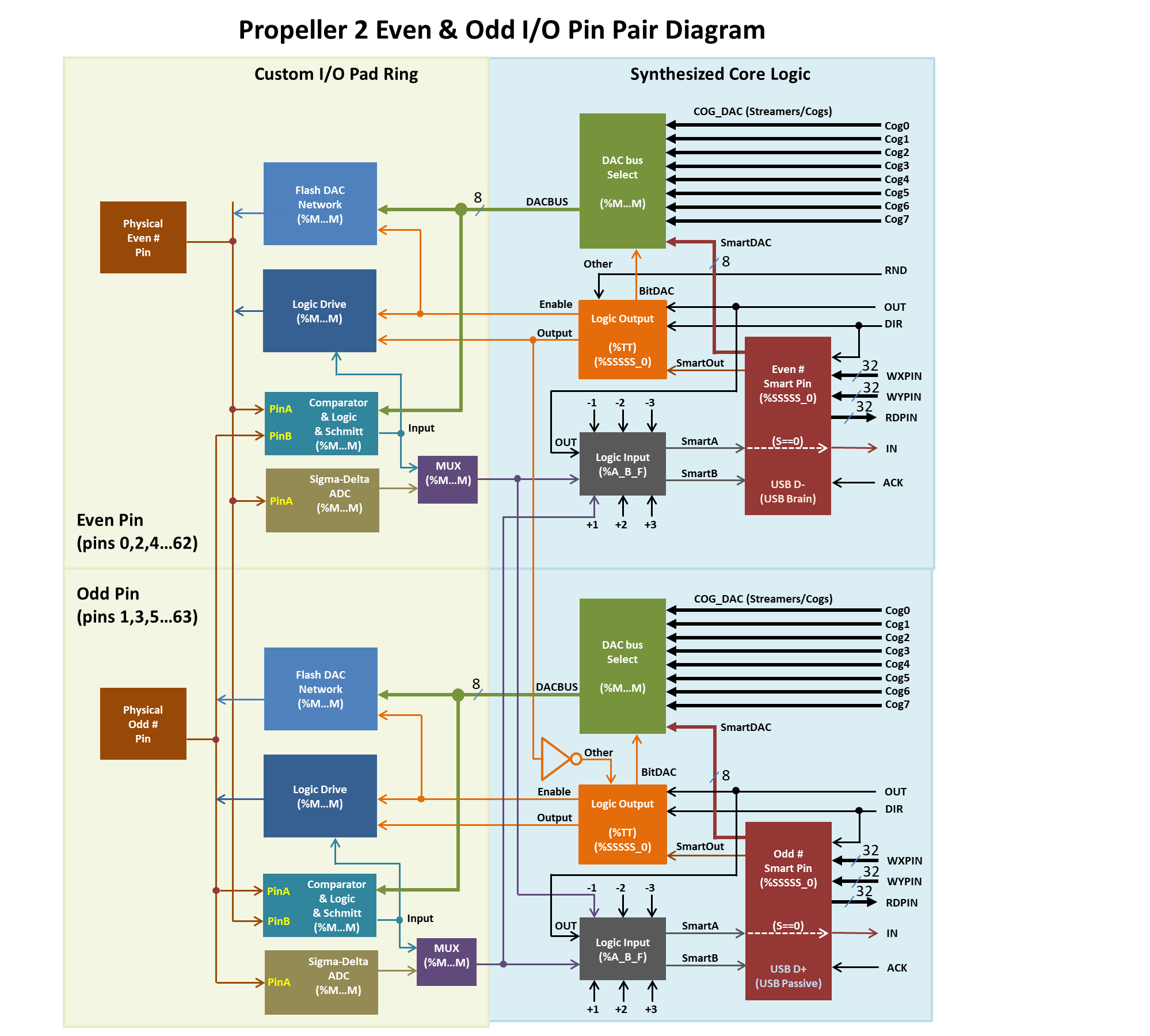
P_PLUS1_Badded to it. ie:P_REG_UP_DOWN + P_SCHMITT_A + P_HIGH_15K + P_OE + P_PLUS1_BI did a little experiment with Spin2.
  pinlow(EDGE_OUT)                                              ' force low
  pinhigh(DIR_OUT)                                              ' count forward

  dif  := DIR_IN - EDGE_IN
  mode := p_reg_up_down | dif.[2..0] << 24

  pinstart(EDGE_IN, mode, 0, 0)

  term.fstr0(@"Creating 100 pulses (incrment)\r")

  repeat 100
    pinhigh(EDGE_OUT)
    waitms(1)
    pinlow(EDGE_OUT)
    waitms(1)

  term.fstr1(@"-- Accumulator = %d\r\r", rdpin(EDGE_IN))

  pinlow(DIR_OUT)                                               ' decrement

  term.fstr0(@"Creating 50 pulses (decrement)\r")

  repeat 50
    pinhigh(EDGE_OUT)
    waitms(1)
    pinlow(EDGE_OUT)
    waitms(1)

  term.fstr1(@"-- Accumulator = %d\r\r", rdpin(EDGE_IN))
I found it best to setup the direction and pulse-generation pins first. Evan's pin B solution is more elegant than my generic which allows any pin that is +/-3 from the A pin.
Ah.....I was just about to report that the config was looking for a high-going pulse and so I got rid of all pull-ups and used external pull-downs.
And also this:
Added the:
And voila")
Many thanks, Evan.
I'm just loving these Smartpins
The smartA/B inputs can be inverted too if you want the smartpin to use low going edges rather than high going. Add
P_INVERT_Aand/orP_INVERT_B.@evanh
@JonnyMac
Thank you, gents. This rapid support is unreal. Only problem is that I'm getting more and more ideas for things