Rayman,
I like your approach with the wire pairs. However, running power down a long cable will give you grief unless there is independent reference for the data wires. Relying on the supply return for the reference gets problematic due to power delivery volt droop. And the thin wires of RJ type cables feels that effect in short order.
Basically you need as a minimum real differential signalling that can operate above and below the power rail and ground respectively. The most rugged approach is isolated signalling like transformer coupled, ie the same as Ethernet, or optocouplers. You can't just have the Prop2 pins direct to the socket.
So once going down that path you may as well support a higher supply voltage to boot. Keep it open ended to allow 50 Volts or so.
The alternative is change the +5 Volt wires into two more GND, don't have power on the cable. That would allow a much longer cable without needing special interface.
EDIT: I guess it does depend on actual power consumption at the load end. If it's only a few mA then I'm probably overreacting.
@evanh Well, for differential signaling, the other way is better for sure. But, not foreseeing doing that.
Things needed for me are TTL serial, I2C, SPI and stuff like that, over short distances.
For long distances, one can use actual ethernet...
Power is something to thing about though... Right now, just using ~10 mA tops. But, was contemplating adding a Nextion display. That will eat power for sure with the backlight...
Suppose reflections are possible... If end of cable is open, suppose could get a 6.6 V back at P2.
But, that'd be if P2 side were open. But, cable impedance is 100 Ohms and P2 output impedance is 20 Ohms when driven normally.
So, think overvoltage would be minimal...
It's around 120 ohms for 3.3 Volt DAC drive. Using BitDAC mode will likely be smoother than Fast logic drive.
wrpin(<pin>, P_DAC_124R_3V | P_BITDAC | ($f0<<8))
BitDAC also provides option to select reduced high-low voltage drive between VIO (3.3 V) and GIO (0 V) of: 0.22, 0.44, 0.66, 0.88, 1.10, 1.32, 1.54, 1.76, 1.98, 2.20, 2.42, 2.64, 2.86, 3.08 Volts. I dunno how useful it is but it's there.
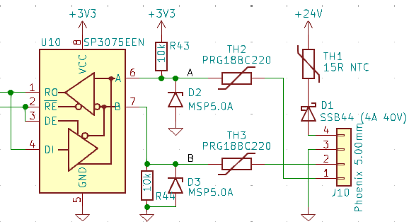
I did belatedly add some protection to my last project that was already using RS485 transceivers.
It wasn't intended for signal integrity though, it was spike/surge protection. We had an incident, before adding any protection, where the 24 Volts ended up on the data lines which then destroyed all the ICs due to back feeding lifting the 3.3 V power rail up to 24 Volts.
The data thermistors are PTC, which ensures the zenors won't cook with 24 V on the data wires. And it is only 9600 baud so no imperative to get top speed from the transceiver.
It's not easy to do this type of protection for logic chips. The zenors are rated for 5 volts but will go higher before clamping hard. That's fine for the transceiver chip as it's designed for the data pins to swing further than the rails.
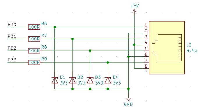
It wouldn't be so easy to make the zenors work for data pins directly on logic chips like the Prop2. And using regular diodes to clamp to the 3.3 V rail just creates a back feed path. Such protection is already present inside the logic chips.
Oh, not so difficult if not worried about surges from bad wiring. Put the zenors on the other side of the resistors. The resistors then allow the data wires to go a little further beyond the rails, giving the zenors more clamping headroom.
@evanh said:
It wasn't intended for signal integrity though, it was spike/surge protection. We had an incident, before adding any protection, where the 24 Volts ended up on the data lines which then destroyed all the ICs due to back feeding lifting the 3.3 V power rail up to 24 Volts.
The data thermistors are PTC, which ensures the zenors won't cook with 24 V on the data wires. And it is only 9600 baud so no imperative to get top speed from the transceiver.
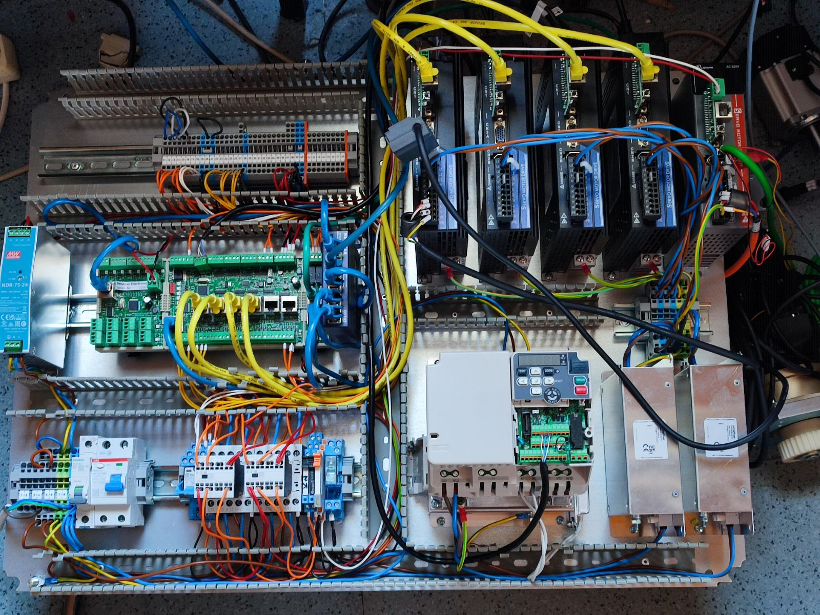
RJ45 cables are really handy. I use them for almost everything where twisted pair cables make sense.
blue: PC ethernet
yellow: step/direction
green: encoder (ABZ differential)
black: MODBUS (RS485)
It's a good idea to choose the pinout in a way that at least inserting a plug in the wrong socket doesn't burn something. This is usually met if no more than +5V is on any pin, all sources are short-circuit protected and all sinks are 5V tolerant. With a little extra effort you can make the transceivers +24V-proof (see #429) but that's not possible in all cases.
For a +5V output you can add a reverse protection diode and increase the voltage regulator output to 5.6V. This way accidentally connecting +24V doesn't backfeed into the 5V bus blowing everything up.
Looks like there is two Prop2 ICs. So you're actually using the RMII interface then? That still impresses me. Not just pulling off raw Ethernet that way but following through with IP and UDP and the likes.
Liking the RG-45 with 5V. It's kind of like a better version of QWIIC but with 4 I/O Pins. This allows for 2X IIC or IIC + bidirectional serial, or SPI, all kinds of things.
Putting 24V on it seems like asking for trouble...
The gas pressure sensor needs 24V power, but found a little 5V to 24V DC-DC converter for that, so no big deal...
@ManAtWork style color coded RJ45 is probably a good idea. Had to go to Amazon to get skinny, flexible ones. Digikey seems to only sell the thick kind...
I prefer Cat5e cables which are quite flexible because they only have a single, common shield. And it still supports up to 300MHz or 1Gbit/s combined using all 4 pairs. Cat6 is a lot thicker and stiffer due to the seperate shields for each pair (PIMF). If required, Cat5e cable is also available for cable chains.
May have been wrong about long Cat5e cable being the problem with I2C over Rj45...
Got a just the right length cable (gray) and it acts up just like the long cable.
The yellow one is perfect.
They are both Cat5e. They both work when nothing moves. But I2C expanders are on a door lid. If you move the door or move the PCBs with the gray cable, the I2C glitches.
Only thing can think of is that the yellow one contacts are slightly longer and slightly shinier. Maybe that's enough to do it...
Guess it’s not a big deal as door moving should be rare in use. Also maybe code should use the ack response to make sure data is valid anyway to be robust.
Kind of lost motivation to change pinout away from PoE style…
568B was included in the standard to cover a preexisting AT&T wiring standard, while 568A is compatible with USOC 1 pair and 2 pair wiring schemes that the US govt prefers. Crossover cables were made with 568A at one end and 568B at the other.
It doesn’t really matter which you use as the only difference is the colour of the insulation.
New Wiznet IO adapter seems to be working with W5500. Seems software for W6100 needs work, but sure it will be OK.
Going to try connecting this board to the bottom board using IDC cable instead of long headers next...
The long headers work, but assembly in the DMB-4775 case is difficult...
In the future, would like to connect this P2 powered "PLC" for this subsystem to an actual Siemens giant PLC that is going to control everything.
Plan is to connect using ethernet driven on P2 side by a Wiznet module.
No idea if that is going to work though...
Guess need to research that...
I used a direct serial Modbus485 on the Prop1. That's what the first schematic above was from. No complex chips like the Wiznet needed then. But of course the other end needed a RS485 port too.
If you get that working from the master side as well, there are thousands of I/O modules from dozens of mfgrs that become available to users of your PLC.


Comments
Rayman,
I like your approach with the wire pairs. However, running power down a long cable will give you grief unless there is independent reference for the data wires. Relying on the supply return for the reference gets problematic due to power delivery volt droop. And the thin wires of RJ type cables feels that effect in short order.
Basically you need as a minimum real differential signalling that can operate above and below the power rail and ground respectively. The most rugged approach is isolated signalling like transformer coupled, ie the same as Ethernet, or optocouplers. You can't just have the Prop2 pins direct to the socket.
So once going down that path you may as well support a higher supply voltage to boot. Keep it open ended to allow 50 Volts or so.
The alternative is change the +5 Volt wires into two more GND, don't have power on the cable. That would allow a much longer cable without needing special interface.
EDIT: I guess it does depend on actual power consumption at the load end. If it's only a few mA then I'm probably overreacting.
@evanh Well, for differential signaling, the other way is better for sure. But, not foreseeing doing that.
Things needed for me are TTL serial, I2C, SPI and stuff like that, over short distances.
For long distances, one can use actual ethernet...
Power is something to thing about though... Right now, just using ~10 mA tops. But, was contemplating adding a Nextion display. That will eat power for sure with the backlight...
Short cable will be okay with a lot more current. The problem with using RJ45 sockets is it's very easy to use any old long Ethernet cable.
The risk of reflections doing damage to logic pins probably goes up with length too.
Suppose reflections are possible... If end of cable is open, suppose could get a 6.6 V back at P2.
But, that'd be if P2 side were open. But, cable impedance is 100 Ohms and P2 output impedance is 20 Ohms when driven normally.
So, think overvoltage would be minimal...
It's around 120 ohms for 3.3 Volt DAC drive. Using BitDAC mode will likely be smoother than Fast logic drive.
BitDAC also provides option to select reduced high-low voltage drive between VIO (3.3 V) and GIO (0 V) of: 0.22, 0.44, 0.66, 0.88, 1.10, 1.32, 1.54, 1.76, 1.98, 2.20, 2.42, 2.64, 2.86, 3.08 Volts. I dunno how useful it is but it's there.
Still protection diodes should prevent damage from 100 ohm source
I did belatedly add some protection to my last project that was already using RS485 transceivers.
It wasn't intended for signal integrity though, it was spike/surge protection. We had an incident, before adding any protection, where the 24 Volts ended up on the data lines which then destroyed all the ICs due to back feeding lifting the 3.3 V power rail up to 24 Volts.
The data thermistors are PTC, which ensures the zenors won't cook with 24 V on the data wires. And it is only 9600 baud so no imperative to get top speed from the transceiver.
It's not easy to do this type of protection for logic chips. The zenors are rated for 5 volts but will go higher before clamping hard. That's fine for the transceiver chip as it's designed for the data pins to swing further than the rails.
It wouldn't be so easy to make the zenors work for data pins directly on logic chips like the Prop2. And using regular diodes to clamp to the 3.3 V rail just creates a back feed path. Such protection is already present inside the logic chips.
Oh, not so difficult if not worried about surges from bad wiring. Put the zenors on the other side of the resistors. The resistors then allow the data wires to go a little further beyond the rails, giving the zenors more clamping headroom.
It was also common to use mini filters on logic data lines like this too. I remember them on parallel and joystick ports from the 1980s.
RJ45 cables are really handy. I use them for almost everything where twisted pair cables make sense.
It's a good idea to choose the pinout in a way that at least inserting a plug in the wrong socket doesn't burn something. This is usually met if no more than +5V is on any pin, all sources are short-circuit protected and all sinks are 5V tolerant. With a little extra effort you can make the transceivers +24V-proof (see #429) but that's not possible in all cases.
For a +5V output you can add a reverse protection diode and increase the voltage regulator output to 5.6V. This way accidentally connecting +24V doesn't backfeed into the 5V bus blowing everything up.
Exercise: Find the propeller(s)
Looks like there is two Prop2 ICs. So you're actually using the RMII interface then? That still impresses me. Not just pulling off raw Ethernet that way but following through with IP and UDP and the likes.
Liking the RG-45 with 5V. It's kind of like a better version of QWIIC but with 4 I/O Pins. This allows for 2X IIC or IIC + bidirectional serial, or SPI, all kinds of things.
Putting 24V on it seems like asking for trouble...
The gas pressure sensor needs 24V power, but found a little 5V to 24V DC-DC converter for that, so no big deal...
Do wish P2 pins were 5V tolerant...
But, if one were to put 24 V on it, then maybe that PoE style pinout would be better...
Actually, 50V with PoE is probably better. Can use off the shelf stuff to supply 50V and convert 50V to 24V...
@ManAtWork style color coded RJ45 is probably a good idea. Had to go to Amazon to get skinny, flexible ones. Digikey seems to only sell the thick kind...
I prefer Cat5e cables which are quite flexible because they only have a single, common shield. And it still supports up to 300MHz or 1Gbit/s combined using all 4 pairs. Cat6 is a lot thicker and stiffer due to the seperate shields for each pair (PIMF). If required, Cat5e cable is also available for cable chains.
May have been wrong about long Cat5e cable being the problem with I2C over Rj45...
Got a just the right length cable (gray) and it acts up just like the long cable.
The yellow one is perfect.
They are both Cat5e. They both work when nothing moves. But I2C expanders are on a door lid. If you move the door or move the PCBs with the gray cable, the I2C glitches.
Only thing can think of is that the yellow one contacts are slightly longer and slightly shinier. Maybe that's enough to do it...
The yellow is shielded, the grey not?
They are both 5e … doesn’t that make them same shielded?
No.
https://cableintelligence.co.uk/blogs/knowledge-centre/are-all-cat5e-cables-the-same#:~:text=F/FTP, S/STP,very much not the same.
I don't think I've ever seen a shielded Cat5 cable in a server room.
Are they use the same twisting?
Type A and Type B cat 5
B is use in Europe, A in US
Yes, all A. Think B is rare these days…
Guess it’s not a big deal as door moving should be rare in use. Also maybe code should use the ack response to make sure data is valid anyway to be robust.
Kind of lost motivation to change pinout away from PoE style…
568B was included in the standard to cover a preexisting AT&T wiring standard, while 568A is compatible with USOC 1 pair and 2 pair wiring schemes that the US govt prefers. Crossover cables were made with 568A at one end and 568B at the other.
It doesn’t really matter which you use as the only difference is the colour of the insulation.
New Wiznet IO adapter seems to be working with W5500. Seems software for W6100 needs work, but sure it will be OK.
Going to try connecting this board to the bottom board using IDC cable instead of long headers next...
The long headers work, but assembly in the DMB-4775 case is difficult...
In the future, would like to connect this P2 powered "PLC" for this subsystem to an actual Siemens giant PLC that is going to control everything.
Plan is to connect using ethernet driven on P2 side by a Wiznet module.
No idea if that is going to work though...
Guess need to research that...
Looks like Modbus TCP can do it. Searching around found a Wiznet hardware example with open source code. Maybe can figure that out...
https://github.com/Wiznet/WIZ550S2E-Modbus/tree/master/WIZ550S2E_App/src
This one might be better:
https://github.com/goddland16/Modbus-TCP
I used a direct serial Modbus485 on the Prop1. That's what the first schematic above was from. No complex chips like the Wiznet needed then. But of course the other end needed a RS485 port too.
If you get that working from the master side as well, there are thousands of I/O modules from dozens of mfgrs that become available to users of your PLC.