

Debug I2C Scanner and BNO086 oddity
 Rayman
Posts: 16,214
Rayman
Posts: 16,214
Made a version of the I2C Scanner in P2 Library from @JonnyMac that uses Debug instead of serial output. This was for my convenience when using Prop Tool.
Seems to be fine with AMG8833 IR grid sensor.
But, when used with BNO086 both it and the original version of the scanner have issues after the first run. The first run always works as it should but later runs mess up...
The Library version gives this sometimes on second run:
P2 I2C Devices
-- dddd_aaa_0 (8-bit) format

   00 02 04 06 08 0A 0C 0E
10 .. .. .. .. .. .. .. ..
20 .. .. .. .. .. .. .. ..
30 .. .. .. .. .. .. .. ..
40 .. .. .. .. .. .. .. ..
50 .. .. .. .. .. .. .. ..
60 .. .. .. .. .. .. .. ..
70 .. .. .. .. .. .. .. ..
80 .. .. .. .. .. .. .. ..
90 .. .. .. 96 98 .. .. ..
A0 .. .. .. .. .. .. .. ..
B0 .. .. .. .. .. .. .. ..
C0 .. .. .. .. .. .. .. ..
D0 .. .. .. .. .. .. .. ..
E0 .. .. .. .. .. .. .. ..

Devices: 2
This is wrong, should only be "96"
Can also give this:
P2 I2C Devices
-- dddd_aaa_0 (8-bit) format

   00 02 04 06 08 0A 0C 0E
10 .. .. .. .. .. .. .. ..
20 .. .. .. .. .. .. .. ..
30 .. .. .. .. .. .. .. ..
40 .. .. .. .. .. .. .. ..
50 .. .. .. .. .. .. .. ..
60 .. .. .. .. .. .. .. ..
70 .. .. .. .. .. .. .. ..
80 .. .. .. .. .. .. .. ..
90 .. .. .. 96 !
Not even sure how this is possible. Sometimes just gives the "!" after "10".
There's not even a "!" in the code, so don't see how this can be.
For the debug version, it just starts showing a device present on all addresses.
How this can be and also be different is also a mystery...
Anyway, seem to have fixed whatever this is by adding a few starts and stops after probing.
But, it doesn't work for the library version, no idea how this can be either...
Anyway, thinking something strange with BNO086 i2c interface...
Comments
Found a nice 7-bit device address list on Adafruit:
https://learn.adafruit.com/i2c-addresses/the-list
Was thinking about starting one, but much better to just use this.
7-bit seems to be the standard for this kind of list?
There's a more official looking one here, but it is pretty useless (although the C++ source code could be useful):
https://i2cdevices.org/devices
Retested the Library version after just changing baud to 230400 and I2c pins and got this on second run:
This is more like what the debug version above used to do before adding start and stop loop...
Wonder if changing baud has something to do with it... No, same at original baud.
BNO086 device is just weird ...
>
The 8th bit is used to distinguish between write or read.
As Christof points out, there are 8-bits in the I2C packet, plus a 9th bit for the ACK/NAK. I started with I2C a long time ago using EEPROMS, and those early datasheets always showed 8 bits, though it was indicated that bit0 was for R/W.
I happened to have an I2C sensor sitting on my desk so I connected it. When everything is working okay, you should see something like this.
Note that I show the addresses in the matrix as 8-bit, but to help the Schmarschmino crowd I also list them in that format.
I've been using debug a bit more lately so I'll see if I can convert that program to use a debug window.
@JonnyMac Used your I2C scanner many times and it's always worked great. This BNO086 thing is first device that acts weird.
Maybe there's some kind of hardware issue here, but it's just a P2 board connected to Sparkfun BNO086 module over a QWIIC connector...
Kind of acting like a power issue, maybe should look into that...
Ok, the serial output above with "!" seems to be a power issue. Switched to another USB port on this laptop and now it acts exactly like with debug (before adding the start/stop loop). That is, first run OK. Second run OK until after it finds it, then thinks something on every address after it. Later runs, thinks something on every address.
This is a new laptop and did notice earlier that a thumbdrive didn't work with the port was using. Think it must not be providing good power...
But, it seems the BNO086 is known to be flaky with I2C interface. There's a note in datasheet that you can't do polling with BNO086, if you want to do polling, you should use BNO085. Also, Sparkfun has notes that you have to connect up reset and interrupt lines to use I2C interface with BNO086.
Reads to me like you can't just talk to the BNO086 whenever you want. You have to wait for interrupt to go low first. And, maybe you have to hard reset the device before it will let you do that.
Slightly improved version of the debug scanner.
Loops every second.
Wish could do the matrix view, but that would take some effort...
Wasn't too bad. It would be nice to have more DEBUG demos to go along with Chip's minimal documentation.
I used the terminal debug window. That said, most of the debug windows graphic images which is why there is no scroll-back capability, so I removed the devices list that shows the 7-bit version of the devices found.
(see updated code below)
Here's a version that matches the original (using PST). It would be nice if the term debug window allowed character color to change on-the-fly.
@JonnyMac Very nice! Didn't know about this "scan" thing. Just what is needed for things like this. That is useful info.
Seems to work. But, my version of the driver maybe doesn't have "PU_EXT".
Ok though 'cause had to change anyway:
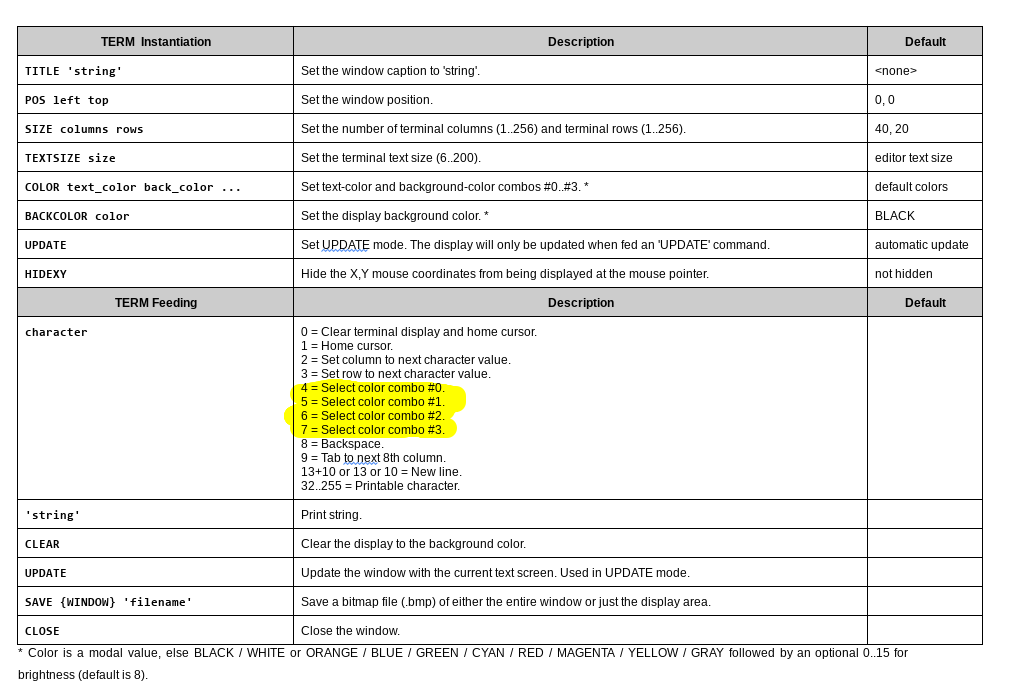
I2C_PU = i2c.PU_15K 'PU_EXTThat is the P2 terminal debug window. Kind of works like an old school text terminal. It would be nice if @cgracey would add
I think with these changes one could mimic ANSI terminal behavior.
Just searched the P2 Spin2 docs for the word "scan" and can't find it... Is it there somewhere?
You have to give your debug windows a name -- I called this one scan.
Here's my setup for that debug terminal window:
@JonnyMac
Think that was enough info to fulfill my wish of using debug like a serial terminal.
This seems to work...
Wishing could do yellow on midnight blue, but can't?
That's a really great idea, Ray, and it will help me with my current work project -- so I'm borrowing it! I added the ability to set the window size and font size in the start() method. I scraped a bunch of my code for simple, hopefully useful, output routines. If we can get Chip to add foreground and background color change on-the-fly, this could be really nice.
@JonnyMac That is nice. Another option for the start() parameters might be to set them in a CON section. Then, use the OBJ section to overwrite the objects constants. Like this:
OBJ

     pwm       : "PWM_Driver" | p = 8, w = 4  'instantiate "PWM_Driver.spin2" as "pwm" with parameters
Like this way, when remember about it, because can set the parameters or not set them as needed.
You can change colors, but only between 4 that you have to declare up-front
Thanks @Wuerfel_21
What am I doing wrong?
I will probably update my version so that passing -1 as an argument sets the default -- I've done that in many objects.
I saw that but have not seen a practical example of defining the color sets, and there is only four sets which seems kind of limiting. That said, I do have a method in my current object that allows one to use the default color sets.
I changed my standard color to cyan-on-black since green-on-black is in the default color set (#2)
You just put up to 8 colors (foreground/background pairs) after
color, likecolor white black red black green black yellow black@Wuerfel_21 Ok, thanks. That works, except "modal" colors, which have to assume means a hex value, seems to be broke.
Can get around that limitation to some extent by specifying the brightness after. Not really happy about not being able to use a hex value though...
So, with this hacked version of "jm_fullduplexserial", called "DebugSerial", can use the original I2C scanner by just changing the object, one line.
Maybe this could work with keyboard input too? Think maybe...
I added methods for configuring the color set values and the background, though using a level with background (which should be possible) causes issues.
Still, this seems serviceable.
Got it to wait for keystroke then erase screen and then redo I2C scan.
Think this is all that is needed for now... Feeling good about it...
Nice! I added colors to my variant and it made me smile a bit -- reminded me of the mid-80s when I worked at Toro and we were using IBM 5150s for golf course irrigation control. We used Turbo Pascal to create a screen painter that would allow us to save the display memory (80 cols x 25 rows with colors) to a file that could be loaded later. I kind of wish we could use that old IBM font in the debug terminal -- that would be fun!
Ok, one last think want to try...
Took that 7-bit address list from web and turned from C++ to something that compiles with PropTool in a dat section.
Maybe not too hard to use to create a "suspect" list from found devices?
Got it. Lists suspects from 7-bit address in list mode.
Not exactly well tested but that first result, the IR camera, is correct...
Very cool. By the way, you might want to change that file to ra_i2c_scanner.spin2 because that's all your work and you should get credit for it.
Am wondering if the 7-bit address is the defacto standard these days. Have seen both 8-bit and 7-bit in the past. Maybe it's all 7-bit now? Hope so, but maybe not...