Another interesting thought wrt. PSRAM usage: If I write a custom driver, I think I could support a "hybrid" mode between fast and slow modes (sysclk/3 and sysclk/2 for QPI PSRAM, sysclk/2 and sysclk/1 for HyperRAM). This would normally use the slower, more reliable speed, but certain transfers could opt into the faster, unreliable speed. Notably, everything related to textures and the framebuffer should be pretty resilient against bit errors and benefit from faster bulk transfer. A risk here is that if the command phase gets corrupted, unrelated memory may be written to, which would be pretty bad. (Though I think the problem usually happens when data is going from the RAM chip to the P2)
@Wuerfel_21 said:
...(Though I think the problem usually happens when data is going from the RAM chip to the P2)
Correct. Write timings are consistently precise because the Prop2 produces the bus clock - For sysclock/2 at least.
Sysclock/1 has struggled in both directions. It was hard to construct a suitable clock-data phase relationship for the write timings at sysclock/1. I hope to make progress on this with the P2Stamp. It may still require adding a small capacitor to tweak clock lagging but I'm hopeful that unregistered clock + registering data will suffice, for writes.
Reads will need all the pin mode combinations. I made some progress on mapping those when testing SD cards at speed. The nice part about this is startup calibration can write to any amount of the RAM to tune itself with. Which wasn't an option with the SD cards.
300-something microseconds saved. The main thing is opportunistically switching to the constant-L version of the texture mapping loop (48 cycles/pixel instead of 56), which overall saves time on both GEO and RAS. The latter is obvious, but it turns out the check is very cheap (10 cycles in fail case) and being able to skip the L gradient computation sometimes makes up for it.
Other than that there's a bunch of more optimized routines and improved control flow.
@Wuerfel_21 said:
Another interesting thought wrt. PSRAM usage: If I write a custom driver, I think I could support a "hybrid" mode between fast and slow modes (sysclk/3 and sysclk/2 for QPI PSRAM, sysclk/2 and sysclk/1 for HyperRAM). This would normally use the slower, more reliable speed, but certain transfers could opt into the faster, unreliable speed. Notably, everything related to textures and the framebuffer should be pretty resilient against bit errors and benefit from faster bulk transfer. A risk here is that if the command phase gets corrupted, unrelated memory may be written to, which would be pretty bad. (Though I think the problem usually happens when data is going from the RAM chip to the P2.
For sysclk/1 writes you would need to delay the clock phase for HyperRAM for reliable command and data latching, and @evanh will no doubt know the intricacies for this with his different board testing and his high speed captures etc. If that is the case it may then make sense to keep writes at sysclk/2 and just do reads optionally at sysclk/1. I'm not sure if registered/unregistered IO pin setting will always resolve the data timing at sysclk/1 rates unlike sysclk/2 which gives you the extra steps to adjust the clock phase.
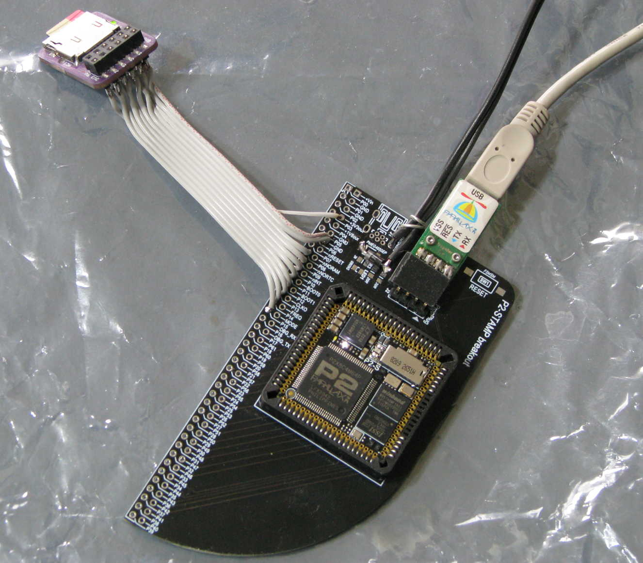
I've ordered a PLCC84 socket to fit in the breakout board that Knivd supplied with the P2Stamp module. Decided I can just pull ten pins out of that to isolate the HyperRAM pins.
Hmm, so it sounds like sysclk/1 is really treacherous. Maybe skip that and focus on the PSRAMs with that idea. Though the win from going sysclk/3 -> sysclk/2 isn't that big, the 96MB type setups that'd need it are already rather bandwidth-constrained. All of the teapot timings have been with @MXX 's 96MB board at 252MHz/2 - going to 320MHz/3 would actually slow things down.
I'm also thinking it would be more optimal if instead of linear rectangles, PSRAM framebuffers were stored with 3 lines packed together in 2048 byte blocks (leaves 128 byte padding). That way no scanline ever crosses a row boundary, unless 4-bit mode is used. You'd need less dense packing (one line with 384 padding bytes) to be 4-bit compliant. Not that those padding areas need to be wasted, they could buffer audio or something.
@evanh said:
I've ordered a PLCC84 socket to fit in the breakout board that Knivd supplied with the P2Stamp module. Decided I can just pull ten pins out of that to isolate the HyperRAM pins.
Done and tested with Roger's 4-bit SD add-on board. Now to get back up to speed with HyperRAM ...
That required a whole detour into figuring out a rounding error that would cause white sparks to appear where the rasterizer disagreed with the L/Z gradient on where the triangle edge is. I don't think I 100% figured it out, but adding a bias to the gradient to stop it from underflowing is good enough.
Different lighting term (source-style half-lambert) that looks less nasty:
EDIT: Another variant: standard lighting term, but squared to sortof-account for gamma:
Good comparison. I don't think I've stopped to look at compares before. Hadn't considered it even.
The middle one - source-style half-lambert - is the easy choice for view-ability. I guess it is kind of a fake ambient lighting effect, that provides an additional gradient on surface spread of light, or something like that?
@evanh said:
Good comparison. I don't think I've stopped to look at compares before. Hadn't considered it even.
The middle one - source-style half-lambert - is the easy choice for view-ability. I guess it is kind of a fake ambient lighting effect, that provides an additional gradient on surface spread of light, or something like that?
Usually you'd have some constant (or vaguely directional) ambient light value to avoid the back side being completely black, but I didn't do that for those screenshots. The half-lambert function lights even the back side somewhat, so less of that is needed and the shape of the object is clearer.
@Wuerfel_21 What are the ranges for yaw, pitch, and roll?
Want to try controlling with 9DOF sensor...
This is what the BNO086 gives me:
Yaw: The yaw is a measure of the rotation around the Z-axis since reset. The yaw has a range of +/- 180˚ and is
provided in 0.01˚ increments, i.e. a report of 8734 is equivalent to 87.34˚.
Pitch: The pitch is a measure of the rotation around the Y-axis. The pitch has a range of +/- 90˚ and is provided in
0.01˚ increments, i.e. a report of 1072 is equivalent to 10.72˚.
Roll: The roll is a measure of the rotation around the X-axis. The roll has a range of +/- 180˚ and is provided in
0.01˚ increments, i.e. a report of 1072 is equivalent to 10.72˚.
@Rayman 32 bit binary angles, just what you'd stuff into QROTATE. Note that you might need to swap the axes, it's very hackneyed (since, really, the proper way is to use quaternions instead of angles)
Have this taking input from BNO086 IMU sensor in RVC mode.
Was relatively simple to implement. Made a little video of it working.
Did figure out that needed to not start the USB input cog because all cogs are otherwise in use.
Also, the dat section that was added needs to be at the bottom of the program for some reason. Breaks things if is located at top of program.
Also, kind of annoying that FlexProp won't give me a .zip file of the code, gives this error:
D:/Propeller2/9DOF/teapot_demo3_2/teapot_demo3_2_wIMU2.spin2:93: error: unknown identifier _setbaud used in function call
error: Unable to write file padmap_builtin.dat to zip
@Rayman said:
Did figure out that needed to not start the USB input cog because all cogs are otherwise in use.
Yeah, jam packed. Need to push all the extra features into the same cogs. Currently the graphics workers have some downtime when the finished frame is being uploaded. So it would be possible to run an audio mixer there. The very end of the audio chain could also go into the video driver, since unlike the emulators, no resampling is needed (can just mix at 32kHz to begin with), so there's a lot of time to do all sorts of things. I'm thinking the mixer might produce Ambisonics B-Format data (4 channels WXYZ) and then the video driver handles converting that to a useful output format on-the-fly. The bigger deal is to make a memory driver that can handle buffering command into PSRAM. The tricky part here is that there's 4 cogs that all need to read the commands and any one can get ahead/fall behind. The raster commands are of course generated from geometry in real time, so there'll need to be some logic to upload those quickly.
Have my eye on the exVGA.spin2 and the exmem_mini.spin2 files.
This looks like it might be an easy way to implement VGA from external memory.
Nice that has many options for video and memory...
Need to double buffer. Is that what you are doing here? Presume so...
Is it easier to flip back and forth between two buffers for the video or have just one that gets copied into from the drawing buffer?
Have my eye on the exVGA.spin2 and the exmem_mini.spin2 files.
This looks like it might be an easy way to implement VGA from external memory.
Nice that has many options for video and memory...
Mind that this is all super hacked together. That's why the HDMI output is 720x480, this is based off the old emulator driver that couldn't handle going directly from scan2x to hsync due to timing sillyness.
Need to double buffer. Is that what you are doing here? Presume so...
Is it easier to flip back and forth between two buffers for the video or have just one that gets copied into from the drawing buffer?
I don't think the scheme I'm doing has a particular name, despite being rather common. Basically, there's 1 active drawing buffer in Hub RAM and 2 display buffers in PSRAM. The picture is assembled in the hub buffer and then copied to one of the PSRAM buffers when done. Then the display pointer is flipped to that one. This fully tearing-free. Note that since my renderer works in 2 phases (GEO->RAS), there's times where the hub buffer doesn't hold image data, but is used to hold the vertex cache (and possibly other things if I get around to implementing more features)
In a unified memory system it doesn't need a separate drawing buffer. But, since the frame buffers have large CPU read latencies, it's much better to have a working draw buffer independent of the double buffered frame buffers. Just so happens the PC world has lived with this same restriction since its inception. Now you mention it, it is odd that that addition has never had a separate name.
@evanh said:
In a unified memory system it doesn't need a separate drawing buffer. But, since the frame buffers have large CPU read latencies, it's much better to have a working draw buffer independent of the double buffered frame buffers. Just so happens the PC world has lived with this same restriction since its inception. Now you mention it, it is odd that that addition has never had a separate name.
Old PC games do mostly draw straight into video RAM. Certainly ones that use 16 color EGA-style modes, because the video card can do fast blits and RMW operations.
Wolf3D takes direct advantage of the column-planes in unchained 256 color mode to reduce VRAM write bandwidth by opportunistically filling multiple identical columns. (The low-detail mode in Doom is also doing that)
A system with a similar scheme I know is the Gamecube/Wii, wherein the GPU has 2MB of on-die PSRAM (Embedded FrameBuffer) that can handle a 192 bit random RMW every cycle (Z-Buffer and alpha blend for 4 pixel blocks w/ 24 bit color+Z!). When the frame is done, it gets compressed to 4:2:2 YCbCr and sent to main memory for scanout (this also clears the EFB). Pretty neat set up. Over on the PS2 side they tried a similar thing with 4MB of DRAM on the GPU, but that also needs to hold the display back buffer (and all textures in use, no transparent caching...) and there's no optimization for that 24 bit sweet spot, it's all either 32 or 16 bit, so either the quality is worse or significant chunk of the fast VRAM is pissed away (or you do interlaced field rendering at 60Hz and never drop -> surprisingly common approach).
That would be awesome. Don't need right away though.
Another question is PSRAM bandwidth. Think seeing that exVGA is pulling video from PSRAM one line at a time.
Would one be correct in presuming that since this can work with PSRAM4, that with PSRAM16 there would be plenty of bandwidth for other cogs to be pulling/pushing lines at the same time?


Comments
@Wuerfel_21 you might be a perfectionist")
I would have moved on…
Of course.
(Though as noted, I had that idea while writing an unrelated program)
Another interesting thought wrt. PSRAM usage: If I write a custom driver, I think I could support a "hybrid" mode between fast and slow modes (sysclk/3 and sysclk/2 for QPI PSRAM, sysclk/2 and sysclk/1 for HyperRAM). This would normally use the slower, more reliable speed, but certain transfers could opt into the faster, unreliable speed. Notably, everything related to textures and the framebuffer should be pretty resilient against bit errors and benefit from faster bulk transfer. A risk here is that if the command phase gets corrupted, unrelated memory may be written to, which would be pretty bad. (Though I think the problem usually happens when data is going from the RAM chip to the P2)
Correct. Write timings are consistently precise because the Prop2 produces the bus clock - For sysclock/2 at least.
Sysclock/1 has struggled in both directions. It was hard to construct a suitable clock-data phase relationship for the write timings at sysclock/1. I hope to make progress on this with the P2Stamp. It may still require adding a small capacitor to tweak clock lagging but I'm hopeful that unregistered clock + registering data will suffice, for writes.
Reads will need all the pin mode combinations. I made some progress on mapping those when testing SD cards at speed. The nice part about this is startup calibration can write to any amount of the RAM to tune itself with. Which wasn't an option with the SD cards.
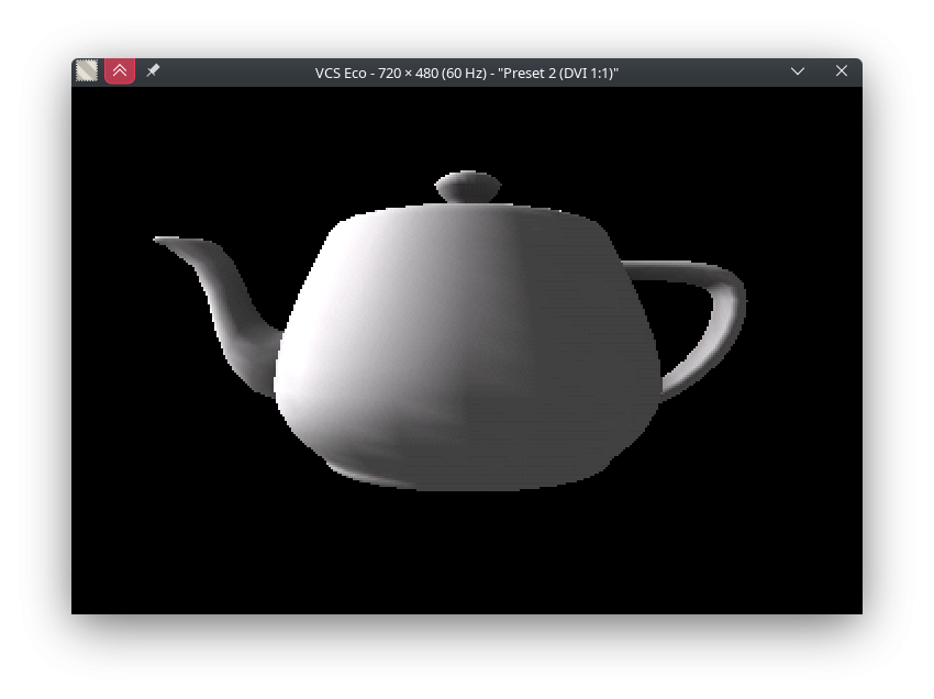
Unrelatedly, here's a "3.2" version of the same teapot demo. I made some further tweaks:
300-something microseconds saved. The main thing is opportunistically switching to the constant-L version of the texture mapping loop (48 cycles/pixel instead of 56), which overall saves time on both GEO and RAS. The latter is obvious, but it turns out the check is very cheap (10 cycles in fail case) and being able to skip the L gradient computation sometimes makes up for it.
Other than that there's a bunch of more optimized routines and improved control flow.
For sysclk/1 writes you would need to delay the clock phase for HyperRAM for reliable command and data latching, and @evanh will no doubt know the intricacies for this with his different board testing and his high speed captures etc. If that is the case it may then make sense to keep writes at sysclk/2 and just do reads optionally at sysclk/1. I'm not sure if registered/unregistered IO pin setting will always resolve the data timing at sysclk/1 rates unlike sysclk/2 which gives you the extra steps to adjust the clock phase.
I've ordered a PLCC84 socket to fit in the breakout board that Knivd supplied with the P2Stamp module. Decided I can just pull ten pins out of that to isolate the HyperRAM pins.
Hmm, so it sounds like sysclk/1 is really treacherous. Maybe skip that and focus on the PSRAMs with that idea. Though the win from going sysclk/3 -> sysclk/2 isn't that big, the 96MB type setups that'd need it are already rather bandwidth-constrained. All of the teapot timings have been with @MXX 's 96MB board at 252MHz/2 - going to 320MHz/3 would actually slow things down.
I'm also thinking it would be more optimal if instead of linear rectangles, PSRAM framebuffers were stored with 3 lines packed together in 2048 byte blocks (leaves 128 byte padding). That way no scanline ever crosses a row boundary, unless 4-bit mode is used. You'd need less dense packing (one line with 384 padding bytes) to be 4-bit compliant. Not that those padding areas need to be wasted, they could buffer audio or something.
Yes scan line alignment to PSRAM rows is always a handy optimization where possible.
It's the only real challenge!") https://forums.parallax.com/discussion/comment/1561510/#Comment_1561510
https://forums.parallax.com/discussion/comment/1561510/#Comment_1561510
Done and tested with Roger's 4-bit SD add-on board. Now to get back up to speed with HyperRAM ...
Messing around with vertex lighting
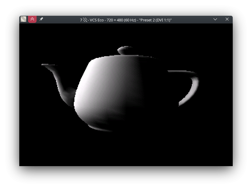
That required a whole detour into figuring out a rounding error that would cause white sparks to appear where the rasterizer disagreed with the L/Z gradient on where the triangle edge is. I don't think I 100% figured it out, but adding a bias to the gradient to stop it from underflowing is good enough.
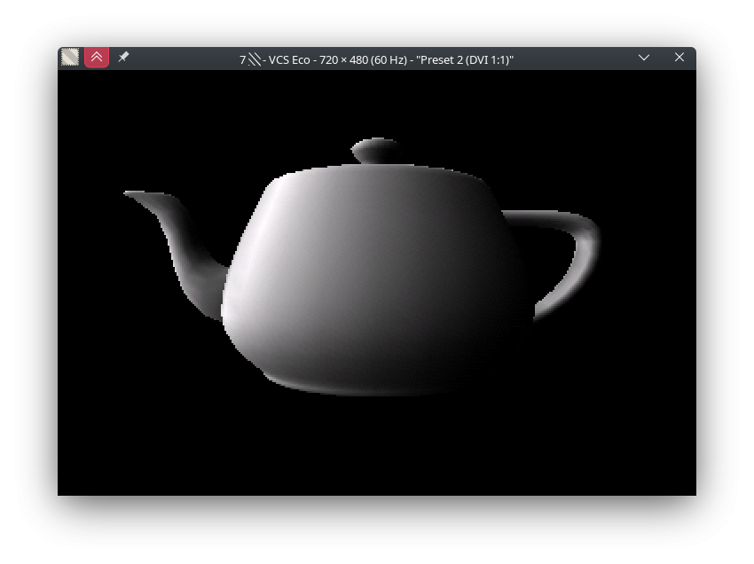
Different lighting term (source-style half-lambert) that looks less nasty:
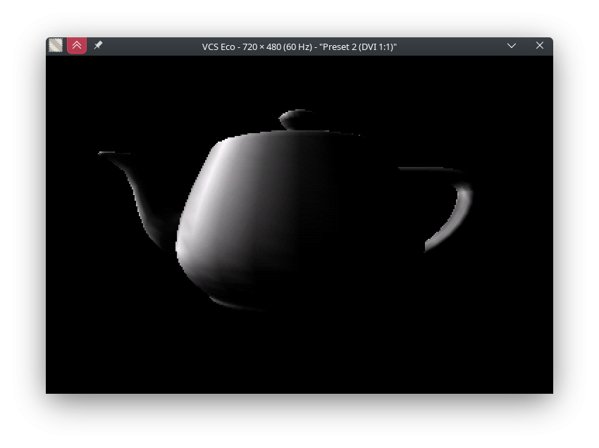
EDIT: Another variant: standard lighting term, but squared to sortof-account for gamma:
Good comparison. I don't think I've stopped to look at compares before. Hadn't considered it even.
The middle one - source-style half-lambert - is the easy choice for view-ability. I guess it is kind of a fake ambient lighting effect, that provides an additional gradient on surface spread of light, or something like that?
The half-lambert idea comes from a presentation on shading techniques used in source engine (check slides 25 onward).
Usually you'd have some constant (or vaguely directional) ambient light value to avoid the back side being completely black, but I didn't do that for those screenshots. The half-lambert function lights even the back side somewhat, so less of that is needed and the shape of the object is clearer.
The actual functions:
              ' dot product
              scas vt_ntx,geo_littest_x
              mov tmp1,0-0
              scas vt_nty,geo_littest_y
              add tmp1,0-0
              scas vt_ntx,geo_littest_z
              add tmp1,0-0
              {' normal
              fges tmp1,#0
              shl tmp1,#1
              add vt_light,tmp1
              '}
              {' normal + gamma approx.
              fges tmp1,#0
              scas tmp1,tmp1
              add vt_light,0-0
              '}
              '{' half-lambertian
              add tmp1,g_con7FFF
              sar tmp1,#1
              scas tmp1,tmp1
              add vt_light,0-0
              '}
        _ret_ fle vt_light,g_conFFFF
(at the end this is still multiplied by the baked AO shade from the model data)
One problem with the half-lambert approach is that the light intensity can't be controlled just by changing the length of the light vector.
For a more fair comparsion, this is the "normal" one with reduced intensity and ambient light:
That sort of thing is very representative of a particular era of fixed-function T&L.
@Wuerfel_21 What are the ranges for yaw, pitch, and roll?
Want to try controlling with 9DOF sensor...
This is what the BNO086 gives me:
Yaw: The yaw is a measure of the rotation around the Z-axis since reset. The yaw has a range of +/- 180˚ and is
provided in 0.01˚ increments, i.e. a report of 8734 is equivalent to 87.34˚.
Pitch: The pitch is a measure of the rotation around the Y-axis. The pitch has a range of +/- 90˚ and is provided in
0.01˚ increments, i.e. a report of 1072 is equivalent to 10.72˚.
Roll: The roll is a measure of the rotation around the X-axis. The roll has a range of +/- 180˚ and is provided in
0.01˚ increments, i.e. a report of 1072 is equivalent to 10.72˚.
@Rayman 32 bit binary angles, just what you'd stuff into QROTATE. Note that you might need to swap the axes, it's very hackneyed (since, really, the proper way is to use quaternions instead of angles)
Have this taking input from BNO086 IMU sensor in RVC mode.
Was relatively simple to implement. Made a little video of it working.
Did figure out that needed to not start the USB input cog because all cogs are otherwise in use.
Also, the dat section that was added needs to be at the bottom of the program for some reason. Breaks things if is located at top of program.
Also, kind of annoying that FlexProp won't give me a .zip file of the code, gives this error:
Yeah, jam packed. Need to push all the extra features into the same cogs. Currently the graphics workers have some downtime when the finished frame is being uploaded. So it would be possible to run an audio mixer there. The very end of the audio chain could also go into the video driver, since unlike the emulators, no resampling is needed (can just mix at 32kHz to begin with), so there's a lot of time to do all sorts of things. I'm thinking the mixer might produce Ambisonics B-Format data (4 channels WXYZ) and then the video driver handles converting that to a useful output format on-the-fly. The bigger deal is to make a memory driver that can handle buffering command into PSRAM. The tricky part here is that there's 4 cogs that all need to read the commands and any one can get ahead/fall behind. The raster commands are of course generated from geometry in real time, so there'll need to be some logic to upload those quickly.
Found another, the ultimate, Teapot ;-)
Wow, that's a big fry!
@Wuerfel_21 Was thinking about reviving this old 90's 3D code and thinking things here can help:
https://forums.parallax.com/discussion/169389/90s-style-3d-now-with-usb-keyboard-scancodes/p1
Have my eye on the exVGA.spin2 and the exmem_mini.spin2 files.
This looks like it might be an easy way to implement VGA from external memory.
Nice that has many options for video and memory...
Need to double buffer. Is that what you are doing here? Presume so...
Is it easier to flip back and forth between two buffers for the video or have just one that gets copied into from the drawing buffer?
Mind that this is all super hacked together. That's why the HDMI output is 720x480, this is based off the old emulator driver that couldn't handle going directly from scan2x to hsync due to timing sillyness.
I don't think the scheme I'm doing has a particular name, despite being rather common. Basically, there's 1 active drawing buffer in Hub RAM and 2 display buffers in PSRAM. The picture is assembled in the hub buffer and then copied to one of the PSRAM buffers when done. Then the display pointer is flipped to that one. This fully tearing-free. Note that since my renderer works in 2 phases (GEO->RAS), there's times where the hub buffer doesn't hold image data, but is used to hold the vertex cache (and possibly other things if I get around to implementing more features)
In a unified memory system it doesn't need a separate drawing buffer. But, since the frame buffers have large CPU read latencies, it's much better to have a working draw buffer independent of the double buffered frame buffers. Just so happens the PC world has lived with this same restriction since its inception. Now you mention it, it is odd that that addition has never had a separate name.
Buffer in hub ram is nice because the 3d does vertical lines which is worst case for psram with horizontal buffer…
But maybe have to think more about that…
Especially if want to increase resolution …
Old PC games do mostly draw straight into video RAM. Certainly ones that use 16 color EGA-style modes, because the video card can do fast blits and RMW operations.
Wolf3D takes direct advantage of the column-planes in unchained 256 color mode to reduce VRAM write bandwidth by opportunistically filling multiple identical columns. (The low-detail mode in Doom is also doing that)
A system with a similar scheme I know is the Gamecube/Wii, wherein the GPU has 2MB of on-die PSRAM (Embedded FrameBuffer) that can handle a 192 bit random RMW every cycle (Z-Buffer and alpha blend for 4 pixel blocks w/ 24 bit color+Z!). When the frame is done, it gets compressed to 4:2:2 YCbCr and sent to main memory for scanout (this also clears the EFB). Pretty neat set up. Over on the PS2 side they tried a similar thing with 4MB of DRAM on the GPU, but that also needs to hold the display back buffer (and all textures in use, no transparent caching...) and there's no optimization for that 24 bit sweet spot, it's all either 32 or 16 bit, so either the quality is worse or significant chunk of the fast VRAM is pissed away (or you do interlaced field rendering at 60Hz and never drop -> surprisingly common approach).
Old PC games were Smile. They don't count as games.
@Wuerfel_21 Is adding sound to the HDMI part of exVGA.spin2 possible?
Well, suppose it is, but how much work is that?
Tons of work") The opposite, adding PSRAM fetch support to the newer driver would be much easier and really what should be done.
The opposite, adding PSRAM fetch support to the newer driver would be much easier and really what should be done.
If this is a formal request, I can probably make it happen within the week.
That would be awesome. Don't need right away though.
Another question is PSRAM bandwidth. Think seeing that exVGA is pulling video from PSRAM one line at a time.
Would one be correct in presuming that since this can work with PSRAM4, that with PSRAM16 there would be plenty of bandwidth for other cogs to be pulling/pushing lines at the same time?