that's a good way to get density in a big box. Do you have a source for those terminal block connectors, and the screw connectors that go into them?
Even the AE knock-offs are really good. I just had to work with some DIN-rail mounted screw-terminal wiring (troubleshooting). Cable trunking, as usual, made access more difficult than I would've liked. I have scuffed fingers again
@Mickster That looks like a stack of thin things, right?
Seen stacks like that for pneumatic stuff too...
Does make me think about having a side port, if there are any extra P2 pins.
Would allow an easy connection to another box that connects on the side...
Looks like can just fit a 1.8" SPI LCD on the top board. Very tight fit, but appears can just squeeze it in...
Was thinking about touchscreen version, but leaning away...
Maybe try to get a couple slide switches and/or buttons on there too...
@Rayman said:
@Mickster That looks like a stack of thin things, right?
Dunno why but that made me chuckle
In this case, yes. A layout style that I am leaning towards though:
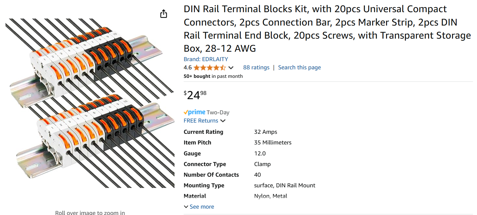
I am a big fan of this type of connector, very maintenance-guy friendly, especially when temporary wires need to be piggy-backed for scope/DMM hook-up.
Going to need to fan out ground wires to 15 or so digital I/O. How would you do that and make it look nice?
Was planning on just plain barrier strips, but maybe that isn't so elegant?
@Rayman said:
Going to need to fan out ground wires to 15 or so digital I/O. How would you do that and make it look nice?
Was planning on just plain barrier strips, but maybe that isn't so elegant?
I might not be on the same wavelength here, but I use these and there are many variants to choose from. The clamping of the wires gives a satisfying feedback:
"Top Hat" DIN Rail
This product is OK when assembling a panel on a workbench but when it comes to releasing a device in the field, it can be quite a struggle....so I only use it as a ledge. My components are fitted with neodymium magnets which hold very firmly. I see that the Chinese are copying me on this because I'm seeing it on other products such as M5Stack
@Rayman said:
Going to need to fan out ground wires to 15 or so digital I/O.
I use these for higher density power handling grounds... there is a bus strip underneath the numbered tabs in the middle that you can cut to length and get solid connection both top and bottom.
But, for signal ground, if I'm not using rj-45, I use the 4-pin versions of the screw terminal block connectors that we'd recently discussed.
Think initial layout is done. Just need to check for errors...
Punted on the magjack ethernet for now, but did bring the traces that are needed out to a header so that ethernet could be implemented with a daughter board.
Kind of amazed could get away with 2 layer boards...
top board has 1.8" LCD, two slide switches and one LED (not sure what will do with slide switches or LED yet though...)
One of our usual suppliers has some DIN terminal blocks.
One variation is "Grounding" and says it grounds the terminals to the DIN rail.
Guess that's OK?
I've seen many boards where the 0V common is connected to the backing plate and din rail. The Omron power supplies have one extra 0v terminal compared with the number of +24 terminals to help enable this.
On the DIN rail terminals, the yellow&green ones have a metal clamp that clamps onto the din rail itself. These also come in double and triple layers
@Rayman said:
Close to ordering the boards. Hope to have it working next week.
Might not start off running ladder logic. But, if it looks like a PLC and it acts like a PLC, then, it's a PLC, right?
Gotta say that @RossH Lua looks a bit tasty.
Broken record here but it would be prudent to plan for integrated motion control. We've mentioned Delta and the Trio MC405 that the P2 can out-perform (Delta's 18 bit motor command notwithstanding).
The PLC functionality of the Delta shares CPU time with the PID loop-rate. We don't have this limitation with the P2.
Over at OMRON, the marketing guys are making a big deal about ridiculously fast loop-rates that are easily achieved by the P2.
I went down a bit of a rabbit hole thinking about pcbs in a rotated orientation, but while still incorporated the Bud DIN enclosures
This is what I came up with so far. Its based loosely on the PC104 system, which uses 15mm Male-Female threaded spacers, and Samtec "ESQ" (or similar) extended stackable headers.
This PCB sits internally in the bud enclosure, but extends connector planes out through openings usually used for terminals. This is useful for
uSD card sockets flush with the upper ledge
Micro HDMI flush with the upper ledge
USB-C flush with upper ledge
9 way pluggable screw terminals (~3.5mm pitch), good for 8 signals + 1 common
slimline D connectors for serial or VGA
right angle 0.1" headers (tight)
Unfortunately RJ45 still a challenge even in this orientation (bit big), but the top section (=lcd panel area) could perhaps be used
I've laser cut up a mockup to check it will fit in the plastic Bud enclosure. I'm not really sold on this concept, but thought I'd throw it out here and see if it stirs some other ideas
@Mickster said:
would be prudent to plan for integrated motion control.
... Delta shares CPU time with the PID loop-rate. We don't have this limitation with the P2.
That could be a real market differential, P2 could handle practically every enhancement unavailable to devices that share processor time with loop.
you seem to be most in tune with this market. can you give us a feature list for your perfect multi-motor motion control system would have.... (while we're on the topic) starting with the physical pinout of pluggable terminal block for each motor (if that is the right connector)
and, just so I'm clear, these are just the control signals for other devices that handle the high power? or, are you talking of working within some power limits defined by NEMA stepper sizes and want to be able to do more clever multimotor integrated control including the power circuits? are you thinking mostly stepper, or brush(less) too?
So much to go through, wouldn't be fair to the thread so I'll start another when I get a breather.
But briefly:
A typical motor/drive combo.
Most drives, today, have onboard controllers which can be commanded via some form of network or can convert stepper-type signals (pulse/direction) to position commands. There are many capable CNC controllers on the market that only output pulse/direction. They cannot be retrofitted to machines with conventional servo drives due to no PID capability.
However, the onboard controllers can be switched off and the drives can then be configured as velocity or current controllers. The command signal is now +10V -10V from an external motion controller.
For some users, having the drive be able to close the feedback loop and simply follow position, velocity and acceleration commands is a good solution but others prefer to handle everything in an external controller and simply use the drive to provide current and commutation to the motor.
A frustrating issue for some machine shops is that they would love to be able to retrofit the aforementioned CNC controller to their existing machining centers but they don't want to have to replace the existing analog-command servo-drives and wiring. So I am working on a solution that accepts pulse/direction as position commands, runs a PID and outputs analog to the existing drives.
Lots of high-end "dead" machines waiting for resurrection
@Mickster said:
So much to go through, wouldn't be fair to the thread so I'll start another when I get a breather.
.....
Lots of high-end "dead" machines waiting for resurrection
great synopsis. so valuable to have input from people in the field close to the pain.
this does deserve another thread.
we're you in on the monthly video chat last night when Chip laid on us the brilliant 8 stepper control with one cog adjusting, every millisecond, the NCO on the SmartPins. that is the unique value I knew was in these smartpins that amplify the P2 beyond all others.
I hope to explore that more.
Was contemplating using a second FT231X chip to enable a second (debug?) interface to PC.
But, just noticed this FTDI FT200XD chip that does kind of the same thing, but with I2C.
Think there's an advantage here because with the P2 being I2C master, data could have several different endpoints with the attached PC just being one of them...
Maybe you could hack something similar with FT231X, but wouldn't be clean...
Scratching my head on this one, but might be something to think about...


Comments
that's a good way to get density in a big box. Do you have a source for those terminal block connectors, and the screw connectors that go into them?
Phoenix:
Phoenix Contact, 3.81mm Pitch, MC 1.5/ 8-ST-3.81, 8 Way, Pluggable Terminal Block, Plug, Cable Mount, Screw: RS-stocknr.: 220-4709; Fabrikantnummer: 1803633
Phoenix Contact, 3.81mm Pitch, MC 1.5/ 8-G-3.81, 8 Way, Right Angle, Pluggable Terminal Block, Header, Wave Soldering: RS-stocknr.: 220-4793; Fabrikantnummer: 1803332
Even the AE knock-offs are really good. I just had to work with some DIN-rail mounted screw-terminal wiring (troubleshooting). Cable trunking, as usual, made access more difficult than I would've liked. I have scuffed fingers again
@Mickster That looks like a stack of thin things, right?
Seen stacks like that for pneumatic stuff too...
Does make me think about having a side port, if there are any extra P2 pins.
Would allow an easy connection to another box that connects on the side...
@refaQtor Does this RJ45 wiring look like close to what you'd want?
thanks
that is the pinout I am using. I usually use 1&2 for serial.
but, yeah, power and ground on those pins.
Looks like can just fit a 1.8" SPI LCD on the top board. Very tight fit, but appears can just squeeze it in...
Was thinking about touchscreen version, but leaning away...
Maybe try to get a couple slide switches and/or buttons on there too...
Dunno why but that made me chuckle
In this case, yes. A layout style that I am leaning towards though:
I am a big fan of this type of connector, very maintenance-guy friendly, especially when temporary wires need to be piggy-backed for scope/DMM hook-up.
I think those connectors on the edge of a stack, like the stack-of-thin-things Delta Computer Systems PLC kit, make the perfect flexibility.
Going to need to fan out ground wires to 15 or so digital I/O. How would you do that and make it look nice?
Was planning on just plain barrier strips, but maybe that isn't so elegant?
I might not be on the same wavelength here, but I use these and there are many variants to choose from. The clamping of the wires gives a satisfying feedback:
"Top Hat" DIN Rail me on this because I'm seeing it on other products such as M5Stack
This product is OK when assembling a panel on a workbench but when it comes to releasing a device in the field, it can be quite a struggle....so I only use it as a ledge. My components are fitted with neodymium magnets which hold very firmly. I see that the Chinese are copying
I use these for higher density power handling grounds... there is a bus strip underneath the numbered tabs in the middle that you can cut to length and get solid connection both top and bottom.
But, for signal ground, if I'm not using rj-45, I use the 4-pin versions of the screw terminal block connectors that we'd recently discussed.
@refaQtor @Mickster These are good looking options, thanks.
Think initial layout is done. Just need to check for errors...
Punted on the magjack ethernet for now, but did bring the traces that are needed out to a header so that ethernet could be implemented with a daughter board.
Kind of amazed could get away with 2 layer boards...
top board has 1.8" LCD, two slide switches and one LED (not sure what will do with slide switches or LED yet though...)
Close to ordering the boards. Hope to have it working next week.
Might not start off running ladder logic. But, if it looks like a PLC and it acts like a PLC, then, it's a PLC, right?
One of our usual suppliers has some DIN terminal blocks.
One variation is "Grounding" and says it grounds the terminals to the DIN rail.
Guess that's OK?
Normally, in a 24 Vdc system, the 0 V common is left floating but connecting to the AC supply earth is an option.
I've seen many boards where the 0V common is connected to the backing plate and din rail. The Omron power supplies have one extra 0v terminal compared with the number of +24 terminals to help enable this.
On the DIN rail terminals, the yellow&green ones have a metal clamp that clamps onto the din rail itself. These also come in double and triple layers
This Wiznet board looks perfect for getting ethernet going:
https://docs.wiznet.io/Product/ioModule/W5500-io
Thinking don't need hardware reset or interrupt lines, so only using 4 P2 pins...
Gotta say that @RossH Lua looks a bit tasty.
Broken record here but it would be prudent to plan for integrated motion control. We've mentioned Delta and the Trio MC405 that the P2 can out-perform (Delta's 18 bit motor command notwithstanding).
The PLC functionality of the Delta shares CPU time with the PID loop-rate. We don't have this limitation with the P2.
Over at OMRON, the marketing guys are making a big deal about ridiculously fast loop-rates that are easily achieved by the P2.
Yellow/Green earthing terminals are not for 0 V common. You can of course jumper them to each other but that colour is reserved for AC earth only.
Oh sure there's normally a separate bank of 0v common for distribution, and purple, orange, grey, or light blue wires typically for 0V.
I haven't seen a 'grounding terminal' like in Ray's photo, that isn't yellow and green, that's new to me.
@tubular yes, it is yellow green…
The regular ones come in a variety of colors, is scheme up to me?
Guess don’t totally understand the floating 24v supply idea. Seen people make a deal about it for something like interlock and e-stop button though.
This is just a vacuum system though with pumps and valves…
If somebody does have a compelling reason to float the 24 supply would like to hear it. Otherwise just going to ground negative side of 24v supply.
Yes, if you don't have customers dictating electrical requirements, then you can go with whatever makes sense to you
I went down a bit of a rabbit hole thinking about pcbs in a rotated orientation, but while still incorporated the Bud DIN enclosures
This is what I came up with so far. Its based loosely on the PC104 system, which uses 15mm Male-Female threaded spacers, and Samtec "ESQ" (or similar) extended stackable headers.
This PCB sits internally in the bud enclosure, but extends connector planes out through openings usually used for terminals. This is useful for
Unfortunately RJ45 still a challenge even in this orientation (bit big), but the top section (=lcd panel area) could perhaps be used
I've laser cut up a mockup to check it will fit in the plastic Bud enclosure. I'm not really sold on this concept, but thought I'd throw it out here and see if it stirs some other ideas
That could be a real market differential, P2 could handle practically every enhancement unavailable to devices that share processor time with loop.
you seem to be most in tune with this market. can you give us a feature list for your perfect multi-motor motion control system would have.... (while we're on the topic) starting with the physical pinout of pluggable terminal block for each motor (if that is the right connector)
and, just so I'm clear, these are just the control signals for other devices that handle the high power? or, are you talking of working within some power limits defined by NEMA stepper sizes and want to be able to do more clever multimotor integrated control including the power circuits? are you thinking mostly stepper, or brush(less) too?
So much to go through, wouldn't be fair to the thread so I'll start another when I get a breather.
But briefly:
A typical motor/drive combo.
Most drives, today, have onboard controllers which can be commanded via some form of network or can convert stepper-type signals (pulse/direction) to position commands. There are many capable CNC controllers on the market that only output pulse/direction. They cannot be retrofitted to machines with conventional servo drives due to no PID capability.
However, the onboard controllers can be switched off and the drives can then be configured as velocity or current controllers. The command signal is now +10V -10V from an external motion controller.
For some users, having the drive be able to close the feedback loop and simply follow position, velocity and acceleration commands is a good solution but others prefer to handle everything in an external controller and simply use the drive to provide current and commutation to the motor.
A frustrating issue for some machine shops is that they would love to be able to retrofit the aforementioned CNC controller to their existing machining centers but they don't want to have to replace the existing analog-command servo-drives and wiring. So I am working on a solution that accepts pulse/direction as position commands, runs a PID and outputs analog to the existing drives.
Lots of high-end "dead" machines waiting for resurrection")
great synopsis. so valuable to have input from people in the field close to the pain.
this does deserve another thread.
we're you in on the monthly video chat last night when Chip laid on us the brilliant 8 stepper control with one cog adjusting, every millisecond, the NCO on the SmartPins.
that is the unique value I knew was in these smartpins that amplify the P2 beyond all others.
I hope to explore that more.
Was contemplating using a second FT231X chip to enable a second (debug?) interface to PC.
But, just noticed this FTDI FT200XD chip that does kind of the same thing, but with I2C.
Think there's an advantage here because with the P2 being I2C master, data could have several different endpoints with the attached PC just being one of them...
Maybe you could hack something similar with FT231X, but wouldn't be clean...
Scratching my head on this one, but might be something to think about...