Are you able to reproduce the issue if you strip out all of your secret bits and replace with some sort of "stubs"? I'd be willing to lend a hand if there's something else wrong with the OLED driver.
I really don't know what it was. The shared I2C pins could explain the hangs. My ethernet driver readys the MAC address from a 24EE048 ROM over I2C. After that the pins are used by the OLED display. But no matter what happens, it shouldn't crash and reboot from flash. There must have been some invalid pointer leading to memory being overwritten.
I don't think there's a bug in the OLED driver. Maybe I've just forgot to set any parameter or flag. I have stripped out all unused code, e.g. the SPI version, 1309 and the scrolling routines. Maybe the driver thought the buffer had to be bigger than what I gave him so it overflowed. Disabling scrolling might have fixed this.
What do you mean with "secret bits"? There's a lot of custom hardware connected on my board and it would be difficult to make a "dummy" without many changes to the code. I think it would be easier to send you a spare board so you can execute the original code without changes. I hope that's not necessary and the spooky behaviour is gone.
Some more progress... The VFD works. I can ramp up and down the RPM and monitor the phase current and calculate the active and reactive current. The current sensors have some really bad temperature drift. There is too much offset even though I do a real time auto-calibration of the P2 ADC pins.
I still need to veryfy if all the protection cirquits work: Brake chopper, overcurrent, overvoltage, overtemperature. Only then I dare to run it directly from mains voltage. Until now I use a DC supply with current limit.
The main loop fits on one page now and looks quite clean. The most difficult part was to figure out all the conversion factors so I can use SI units (Hz, A, V RMS) for the parameters.
void UpdateVfd ()
// update real time variables for VFD control loop
{
  drv.WaitCycle ();
  float vIn= drv.voltBus * adcToVoltDc;
  if (vIn > VdcMin) vDC= vIn + voltDcOffset;
  vMax= vDC / sqrt2;
  float df= fNom - fAct;          // delta speed = nominal - actual
  if (df > fAcc) df= fAcc;        // ramp up
  else if (df < -fAcc) df= -fAcc; // ramp down
  fAct+= df;
  if (fAct > fMax) fAct= fMax;
  else if (fAct < 0.0) fAct= 0.0;
  currTot= drv.currAmpl * cGain;   // total current
  currAng= drv.currPhi * binToRad - fAct * aGain; // corrected phase angle
  currQ  = currTot * cos(currAng); // active current (~torque)
  fBoost = currQ * sGain;          // slip ~ torque
  float fSum= fAct + fBoost;
  vBoost = currQ * xGain * fSum + currTot * motR;
  if (fSum < motFN) vMot= fSum * vGain; // base range (triangle)
  else vMot= vBase;                     // field weakening range (flat)
  vMot+= vIdle + vBoost;
  if (fAct < fMin)
  {
    currTot= 0.0;
    drv.voltAmpl= 0;
    drv.voltFreq= 0;
  }
  else
  {
    if (vMot > vMax) vMot= vMax; // clipping limit
    drv.voltAmpl= round (vMot / vDC * voltToPwm);
    drv.voltFreq= round (fSum * freqToBin);
  }

  printf ("currTot=%f\n", currTot);
  //printf ("cnt=%d vDC=%f ampl=%d\n", drv.voltBus, vDC, drv.voltAmpl);
  //printf ("`MyScope %d, %d, %d\n", drv.dutyU, drv.dutyV, drv.dutyW);
  printf ("`MyScope %d, %d, %d\n", drv.currActU, drv.currActV, drv.currActW);
}
Although I thought my PCB design was quite clean with solid ground planes and termination resistors at the bus lines I found a problem with the SPI bus. Reading registers from the Trinamic chips works OK if there are only 3 of 5 plugged into the doughterboard slots.
Since the results are repeatable I think it's not noise but wave reflections/ringing on the bus lines. That can be a bit difficult to debug because adding 10pF of capacitance of the scope probe changes the conditions and also the results.
Any more than three out of five or some specific combinations of the more than three ?
The answer to this question might aid with debugging.
Just a thought.
I've exchanged the 5 daughterboards but with no effect. I watched the waveforms of the SCLK, MISO and MOSI signals. They were clean and without any overshot. But I found out that the command byte (MOSI) of the first chip selected sometimes was totally messed up. Always resetting the serial out smart pin before activating chip select fixed that.
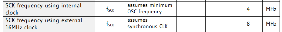
Then I saw that the MISO signal had randomly dithering delay of one or two clocks. That was an indication that the Trinamic chips missed some of the clocks. As the signal level and rise/fall times were completely perfect without any ringing or noise that could only mean that the clock was too fast for them. I looked up the data sheet.
My external clock is 12 instead of 16MHz so I assumed that 6MHz SCLK would be OK. But it wasn't. I've reduced it to 4MHz and now it works perfectly. Reading and writing from/to the registers is for configuration, only, and doesn't affect the performance of the motor. So I don't have to care about max. speed.
You've solved your problem. That is excellent news.
I've looked over the most current revision of the datasheet of this chip and heck, these smart asses can't even be blamed they lied.
They simply do not give the max SCK frequency but instead specify it only at internal or 16 MHz external clock (no mention of itermediate frequencies whatsoever).
The funny thing is you used 12 MHz external clock which is perfectly valid (typical factory calibrated) and they use it to specify the current consumption at 5V.
As it happens more often than not these days, one can only have limited trust in datasheets.
Yeah, exactly. I can guess what caused the problem. The specification of allowing fSCK to be half of the OSC frequency relies on the assumption that SCK has a perfect 50/50 duty cycle. So no high or low phase can be missed when the SPI clock is internally synchronized to the master clock. But of course, that assumption is never guaranteed to be valid. There should always be a safety margin but they don't tell you. I've seen much worse data sheets, recently, where almost no trustworthy information was given but only "typical" values. You have to find out by trial and error what works and what doesn't. It's like in the commercial ads: "Don't claim any specific number, so they can't sue you"
@avsa242 said:
Are you able to reproduce the issue if you strip out all of your secret bits and replace with some sort of "stubs"? I'd be willing to lend a hand if there's something else wrong with the OLED driver.
Hi Jesse,
as I said earlier, I encountered some strange problems with the OLED driver that appeared and disappeared seemingly randomly as I changed the order of calling some functions in my code. But now, I'm able to reproduce the problem. The symptoms are that _getms() always returns -1 instead of the time since reset as it should. This happens as soon as I call disp.clear() in my initialisation code for the display.
void Start ()
{
  disp.startx (SCL_PIN, SDA_PIN, RES_PIN, SCL_FREQ, ADDR_BITS, D_WIDTH, D_HEIGHT, &_framebuff);
  disp.fontscale (1,1);
  ChangeFont (true);
  disp.preset_128x64 ();
  disp.mirror_h (false);
  disp.mirror_v (false);
  /*
  disp.clear (); // <- problem shows up as soon as I execute this
  disp.fgcolor (1);
  disp.char_attrs (disp.DRAWBG);
  disp.show ();
  */
  lastUpdate= _getms();
  printf ("lastUpdate = %d\n", lastUpdate);
}
I guess that clearing the display buffer somehow overwrites the hub memory where the clock frequency is stored so that the QDIV used in _getms() triggers an overflow (divide by zero). I'll try to debug that by adding guards to the buffer. And I'm almost sure it's my own fault and not a bug in the driver.
In the case I'm not able to sort it out... I've commented out all the other code that needs my special hardware. So theoretically it should run on a KISS board with just the OLED display connected to two pins. You've got a KISS board and an SSD1306 display, haven't you.
Today, I had to fix some really silly bugs such as
BMASK 1 returns a mask of two bits and not just one
I forgot to solder in the common mode chokes into my board and thus no power was delivered to the motors
But now I can also run the stepper motors. There are some minor issues like jerks and vibrations when switching between the different speed regimes. But I hope I can fix this by fine tuning the values in the abundance of configuration registers of the Trinamic chips.
There were some questions in the live forum yesterday which I haven't fully answered. So I'll do it here.
Load detection, encoder and rigid tapping.
The hardware has an encoder input but the software doesn't use it, at the moment. I plan to add that later. The VFD software can detect the torque present at the motor to compensate the load and keep the RPM constant. This is especially important at lower speed. Cheap high frequency spindles with a top speed of 24,000 RPM are usually rated for 6000 RPM minimum because cheap VFDs without vector control don't deliver any usable torque below that. By measuring the current vector I can reliably measure the torque and can boost the voltage and frequency to compensate for slip and voltage drop due to winding losses. This way I can deliver full nominal torque from 600RPM and above.
But it's not designed as servo drive which could do precise positional control at standstill. As the spindle motors are asynchronous (squirrel cage induction motors) there is always some slip between the stator field and the rotor orientation. By adding an encoder it could still be used for rigid tapping. This can be implemented by letting the Z axis (stepper or servo drive) follow the spindle rotation through an electronic gear. This would allow slight speed variations (<1% but not totally avoidable) while still ensuring high thread pitch accuracy.
TCP/IP itself is not very hard to implement. I actually implemented my own protocol which also supports reliable data transmission with acknowledging and packet retransmission in the case of lost packets. It works very similar to what TCP does. The trouble with TCP/IP is that you need an IP adress, first. This is easy for the typical network setup where a router offers DHCP service. You ask for an IP adress and you get it. But you can't take that for granted in all cases. There are peer-to-peer networks without a DHCP server. There you have to manually assign the IP adresses because you don't know if some of the peers is not responding because it's temporarily switched off. Then there is the case of only one CNC controller connected directly to only one PC.
Some devices like a Fritz-box solve this issue with clever software. You can always type "fritz.box" in your browser and the box connects automatically. But this takes some actions that are highly non-trivial. At least with the P1 there were not enough resources to do it like that.
With some products of cometitors (Eding CNC for example) the process to assign an IP adress is rediculously complex. The CNC controller is shipped with a fixed IP adress. The manual tells you to set the IP address of your PC to an address in the same subnet domain but with a different last byte. Then you can connect to the controller, change its IP address to whatever you need to fit your existing network. And finally, you have to change the IP address of the PC back to the original one.
But that's not how it should be. As Chip pointed out in the live forum during the Maker Plot discussion, operators of industrial machines don't want to deal with network administration or care about software settings for the connections. They don't even know what an IP address is. They want to plug in the cable, press a button and it has to work. Period.
So I decided to drop TCP/IP. I simply picked a type ID that is not used by anyone else and implemented my own protocol. It's not visible by IP traffic and vice versa. So I can simply send a broadcast and ask all my connected devices to reply to it. I display a list of all devices with their name. The user can pick one and presses OK. Because all replies to the broadcast contains the MAC address of the device I have all I need.
Now, that I have some spare memory in the P2 there might be better ways to do it. But it was definitely the simplest way for both me and the user at the time I have deverlopped the first controller.
operators of industrial machines don't want to deal with network administration or care about software settings for the connections. They don't even know what an IP address is. They want to plug in the cable, press a button and it has to work. Period.
Another puzzle to solve.
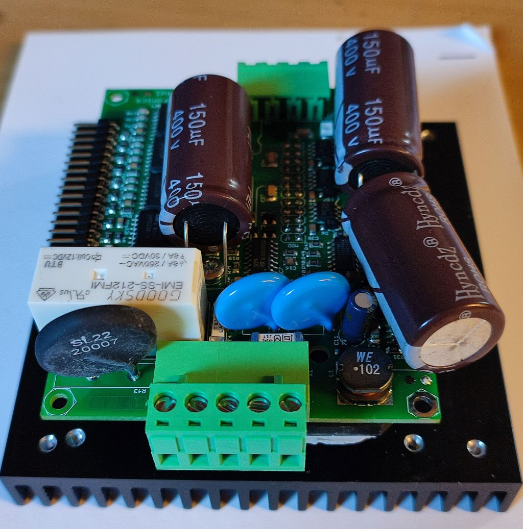
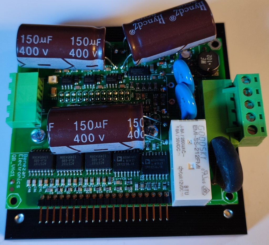
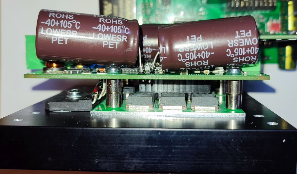
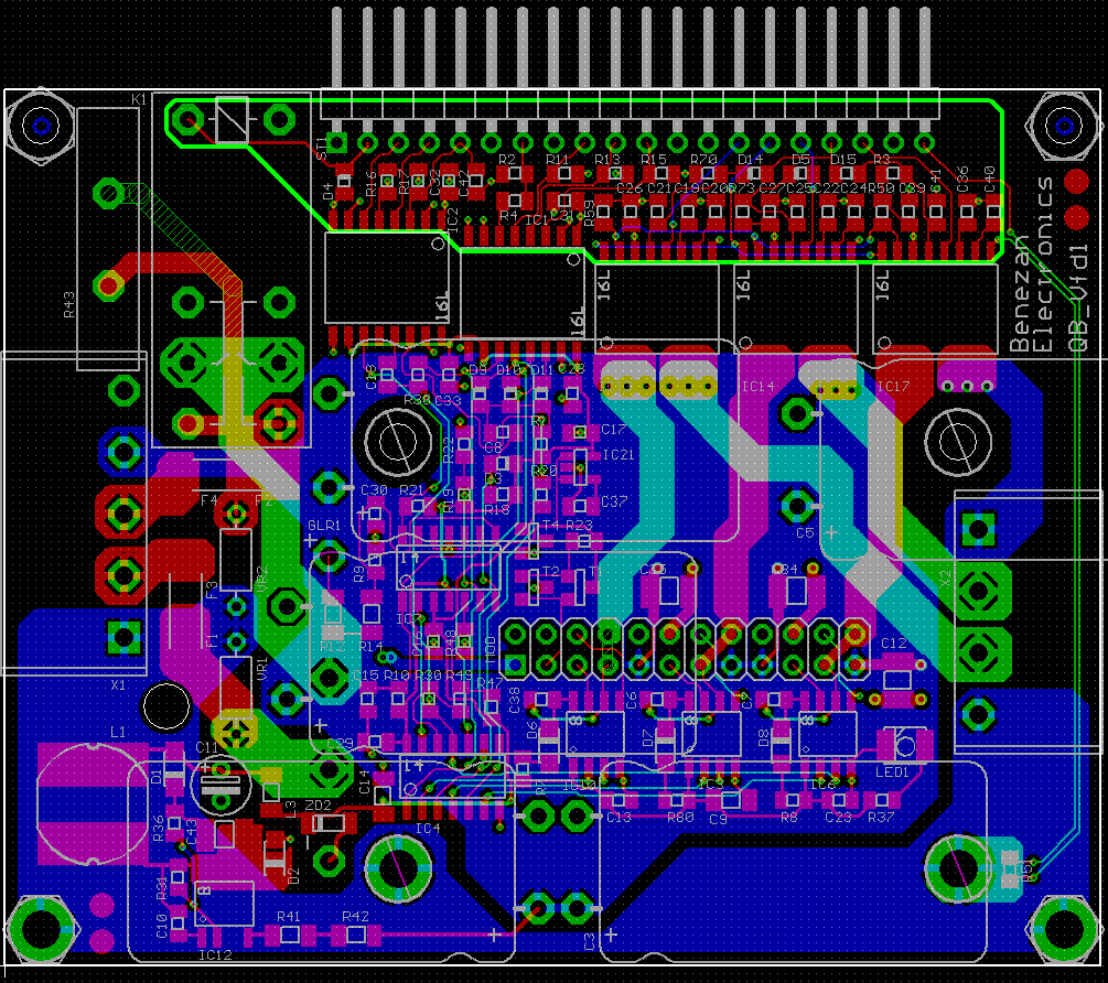
This is a new PCB layout of the VFD doughter board. It's almost the same schematic but with smaller caps and the heatsink flipped to the bottom.
@DigitalBob said:
For a $130 US you can get a USB to parallel interface, runs Mach3 and Mach4. Checkout CNC drive motion controls.
Does this $130 include the license for Mach3/4? And what can you do with a parallel interface alone? Nothing. You need a breakout board, motor drivers, a VFD for the spindle and you need somebody who can do all the wiring without blowing things up. And don't forget the safety relay for the door switches costs >$100.
So add that up
USB-parallel interface $130
VFD $100
breakout board $10
4 stepper drivers $100
wiring work $100
safety relay $100
total: $540
And I think that is rather optimistic and does only account for the recurring work if you already have experience. If not you need to invest much more time to read all the different documentation from different manufacturers, setup the VFD properly for your motor, configure the IOs in Mach3 and so on.
The Mach 3 and 4 are free, as long as your only running small jobs and not large production. Does the wiener schnitzel controller come with a VFD, interface, breakout, four steppers, relay, for $500
@DigitalBob said:
The Mach 3 and 4 are free, as long as your only running small jobs and not large production.
I'm not talking about a DIY solution. Yes, some of my customers are hobbyists. But if you sell a serious all-in-one solution you have to include the licence.
Does the wiener schnitzel controller come with a VFD, interface, breakout, four steppers, relay, for $500
What? Why "wiener schnitzel"? My BOM cost is currently around $120. So yes, I can sell it for $500 and make some reasonable profit, I hope.
We already had that discussion, before. (see here) You can always make it cheaper. And I can't compete and don't want to compete with Chinese products made for DIY people. They don't count their work hours. A guy from the nex village has built a milling machine completely from scrapyard parts. Yes, you can do that. And if you don't count your time then it's damn cheap. I have great respect for somebody doing this. But I don't try to sell them anything.
On holes that may be stressed like big parts, high currents, and connectors, we started adding redundant vias to top traces, so the plating was never the sole path.
Saw a few field failures where the thru-plating fractured if the solder had not fully wicked to the top trace, due to mechanical stress.
We also used oversized offset oval pads on the manual solder parts, gives good thermal contact for the iron, and more adhesion.


Comments
Are you able to reproduce the issue if you strip out all of your secret bits and replace with some sort of "stubs"? I'd be willing to lend a hand if there's something else wrong with the OLED driver.
Cheers
I really don't know what it was. The shared I2C pins could explain the hangs. My ethernet driver readys the MAC address from a 24EE048 ROM over I2C. After that the pins are used by the OLED display. But no matter what happens, it shouldn't crash and reboot from flash. There must have been some invalid pointer leading to memory being overwritten.
I don't think there's a bug in the OLED driver. Maybe I've just forgot to set any parameter or flag. I have stripped out all unused code, e.g. the SPI version, 1309 and the scrolling routines. Maybe the driver thought the buffer had to be bigger than what I gave him so it overflowed. Disabling scrolling might have fixed this.
What do you mean with "secret bits"? There's a lot of custom hardware connected on my board and it would be difficult to make a "dummy" without many changes to the code. I think it would be easier to send you a spare board so you can execute the original code without changes. I hope that's not necessary and the spooky behaviour is gone.
I just meant any part of your application program you may not want to have shared, so just the bare minimum code that still reproduces the problem.
Some more progress... The VFD works. I can ramp up and down the RPM and monitor the phase current and calculate the active and reactive current. The current sensors have some really bad temperature drift. There is too much offset even though I do a real time auto-calibration of the P2 ADC pins.
I still need to veryfy if all the protection cirquits work: Brake chopper, overcurrent, overvoltage, overtemperature. Only then I dare to run it directly from mains voltage. Until now I use a DC supply with current limit.
The main loop fits on one page now and looks quite clean. The most difficult part was to figure out all the conversion factors so I can use SI units (Hz, A, V RMS) for the parameters.
void UpdateVfd () // update real time variables for VFD control loop { drv.WaitCycle (); float vIn= drv.voltBus * adcToVoltDc; if (vIn > VdcMin) vDC= vIn + voltDcOffset; vMax= vDC / sqrt2; float df= fNom - fAct; // delta speed = nominal - actual if (df > fAcc) df= fAcc; // ramp up else if (df < -fAcc) df= -fAcc; // ramp down fAct+= df; if (fAct > fMax) fAct= fMax; else if (fAct < 0.0) fAct= 0.0; currTot= drv.currAmpl * cGain; // total current currAng= drv.currPhi * binToRad - fAct * aGain; // corrected phase angle currQ = currTot * cos(currAng); // active current (~torque) fBoost = currQ * sGain; // slip ~ torque float fSum= fAct + fBoost; vBoost = currQ * xGain * fSum + currTot * motR; if (fSum < motFN) vMot= fSum * vGain; // base range (triangle) else vMot= vBase; // field weakening range (flat) vMot+= vIdle + vBoost; if (fAct < fMin) { currTot= 0.0; drv.voltAmpl= 0; drv.voltFreq= 0; } else { if (vMot > vMax) vMot= vMax; // clipping limit drv.voltAmpl= round (vMot / vDC * voltToPwm); drv.voltFreq= round (fSum * freqToBin); } printf ("currTot=%f\n", currTot); //printf ("cnt=%d vDC=%f ampl=%d\n", drv.voltBus, vDC, drv.voltAmpl); //printf ("`MyScope %d, %d, %d\n", drv.dutyU, drv.dutyV, drv.dutyW); printf ("`MyScope %d, %d, %d\n", drv.currActU, drv.currActV, drv.currActW); }Although I thought my PCB design was quite clean with solid ground planes and termination resistors at the bus lines I found a problem with the SPI bus. Reading registers from the Trinamic chips works OK if there are only 3 of 5 plugged into the doughterboard slots.
But if all 5 are present I get corrupted data.
Since the results are repeatable I think it's not noise but wave reflections/ringing on the bus lines. That can be a bit difficult to debug because adding 10pF of capacitance of the scope probe changes the conditions and also the results.
Any more than three out of five or some specific combinations of the more than three ?
The answer to this question might aid with debugging.
Just a thought.
I've exchanged the 5 daughterboards but with no effect. I watched the waveforms of the SCLK, MISO and MOSI signals. They were clean and without any overshot. But I found out that the command byte (MOSI) of the first chip selected sometimes was totally messed up. Always resetting the serial out smart pin before activating chip select fixed that.
Then I saw that the MISO signal had randomly dithering delay of one or two clocks. That was an indication that the Trinamic chips missed some of the clocks. As the signal level and rise/fall times were completely perfect without any ringing or noise that could only mean that the clock was too fast for them. I looked up the data sheet.
My external clock is 12 instead of 16MHz so I assumed that 6MHz SCLK would be OK. But it wasn't. I've reduced it to 4MHz and now it works perfectly. Reading and writing from/to the registers is for configuration, only, and doesn't affect the performance of the motor. So I don't have to care about max. speed.
You've solved your problem. That is excellent news.
I've looked over the most current revision of the datasheet of this chip and heck, these smart asses can't even be blamed they lied.
They simply do not give the max SCK frequency but instead specify it only at internal or 16 MHz external clock (no mention of itermediate frequencies whatsoever).
The funny thing is you used 12 MHz external clock which is perfectly valid (typical factory calibrated) and they use it to specify the current consumption at 5V.
As it happens more often than not these days, one can only have limited trust in datasheets.
That aside, these TMC1560A chips are really good.
Yeah, exactly. I can guess what caused the problem. The specification of allowing fSCK to be half of the OSC frequency relies on the assumption that SCK has a perfect 50/50 duty cycle. So no high or low phase can be missed when the SPI clock is internally synchronized to the master clock. But of course, that assumption is never guaranteed to be valid. There should always be a safety margin but they don't tell you. I've seen much worse data sheets, recently, where almost no trustworthy information was given but only "typical" values. You have to find out by trial and error what works and what doesn't. It's like in the commercial ads: "Don't claim any specific number, so they can't sue you"
Hi Jesse,
as I said earlier, I encountered some strange problems with the OLED driver that appeared and disappeared seemingly randomly as I changed the order of calling some functions in my code. But now, I'm able to reproduce the problem. The symptoms are that _getms() always returns -1 instead of the time since reset as it should. This happens as soon as I call disp.clear() in my initialisation code for the display.
void Start ()
{ disp.startx (SCL_PIN, SDA_PIN, RES_PIN, SCL_FREQ, ADDR_BITS, D_WIDTH, D_HEIGHT, &_framebuff); disp.fontscale (1,1); ChangeFont (true); disp.preset_128x64 (); disp.mirror_h (false); disp.mirror_v (false); /* disp.clear (); // <- problem shows up as soon as I execute this disp.fgcolor (1); disp.char_attrs (disp.DRAWBG); disp.show (); */ lastUpdate= _getms(); printf ("lastUpdate = %d\n", lastUpdate); }I guess that clearing the display buffer somehow overwrites the hub memory where the clock frequency is stored so that the QDIV used in _getms() triggers an overflow (divide by zero). I'll try to debug that by adding guards to the buffer. And I'm almost sure it's my own fault and not a bug in the driver.
In the case I'm not able to sort it out... I've commented out all the other code that needs my special hardware. So theoretically it should run on a KISS board with just the OLED display connected to two pins. You've got a KISS board and an SSD1306 display, haven't you.
Just want to be sure, but the
address()method in the SSD1306 thread was the cause of all this?Yes, problem solved. No more crashes or other funny behaviour, and no need for you to help debugging.
Today, I had to fix some really silly bugs such as
But now I can also run the stepper motors. There are some minor issues like jerks and vibrations when switching between the different speed regimes. But I hope I can fix this by fine tuning the values in the abundance of configuration registers of the Trinamic chips.
There were some questions in the live forum yesterday which I haven't fully answered. So I'll do it here.
The hardware has an encoder input but the software doesn't use it, at the moment. I plan to add that later. The VFD software can detect the torque present at the motor to compensate the load and keep the RPM constant. This is especially important at lower speed. Cheap high frequency spindles with a top speed of 24,000 RPM are usually rated for 6000 RPM minimum because cheap VFDs without vector control don't deliver any usable torque below that. By measuring the current vector I can reliably measure the torque and can boost the voltage and frequency to compensate for slip and voltage drop due to winding losses. This way I can deliver full nominal torque from 600RPM and above.
But it's not designed as servo drive which could do precise positional control at standstill. As the spindle motors are asynchronous (squirrel cage induction motors) there is always some slip between the stator field and the rotor orientation. By adding an encoder it could still be used for rigid tapping. This can be implemented by letting the Z axis (stepper or servo drive) follow the spindle rotation through an electronic gear. This would allow slight speed variations (<1% but not totally avoidable) while still ensuring high thread pitch accuracy.
TCP/IP itself is not very hard to implement. I actually implemented my own protocol which also supports reliable data transmission with acknowledging and packet retransmission in the case of lost packets. It works very similar to what TCP does. The trouble with TCP/IP is that you need an IP adress, first. This is easy for the typical network setup where a router offers DHCP service. You ask for an IP adress and you get it. But you can't take that for granted in all cases. There are peer-to-peer networks without a DHCP server. There you have to manually assign the IP adresses because you don't know if some of the peers is not responding because it's temporarily switched off. Then there is the case of only one CNC controller connected directly to only one PC.
Some devices like a Fritz-box solve this issue with clever software. You can always type "fritz.box" in your browser and the box connects automatically. But this takes some actions that are highly non-trivial. At least with the P1 there were not enough resources to do it like that.
With some products of cometitors (Eding CNC for example) the process to assign an IP adress is rediculously complex. The CNC controller is shipped with a fixed IP adress. The manual tells you to set the IP address of your PC to an address in the same subnet domain but with a different last byte. Then you can connect to the controller, change its IP address to whatever you need to fit your existing network. And finally, you have to change the IP address of the PC back to the original one.
But that's not how it should be. As Chip pointed out in the live forum during the Maker Plot discussion, operators of industrial machines don't want to deal with network administration or care about software settings for the connections. They don't even know what an IP address is. They want to plug in the cable, press a button and it has to work. Period.
So I decided to drop TCP/IP. I simply picked a type ID that is not used by anyone else and implemented my own protocol. It's not visible by IP traffic and vice versa. So I can simply send a broadcast and ask all my connected devices to reply to it. I display a list of all devices with their name. The user can pick one and presses OK. Because all replies to the broadcast contains the MAC address of the device I have all I need.
Now, that I have some spare memory in the P2 there might be better ways to do it. But it was definitely the simplest way for both me and the user at the time I have deverlopped the first controller.
operators of industrial machines don't want to deal with network administration or care about software settings for the connections. They don't even know what an IP address is. They want to plug in the cable, press a button and it has to work. Period.
Craig
Another puzzle to solve.
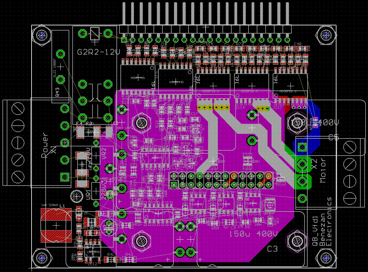
This is a new PCB layout of the VFD doughter board. It's almost the same schematic but with smaller caps and the heatsink flipped to the bottom.
For a $130 US you can get a USB to parallel interface, runs Mach3 and Mach4. Checkout CNC drive motion controls.
Does this $130 include the license for Mach3/4? And what can you do with a parallel interface alone? Nothing. You need a breakout board, motor drivers, a VFD for the spindle and you need somebody who can do all the wiring without blowing things up. And don't forget the safety relay for the door switches costs >$100.
So add that up
total: $540
And I think that is rather optimistic and does only account for the recurring work if you already have experience. If not you need to invest much more time to read all the different documentation from different manufacturers, setup the VFD properly for your motor, configure the IOs in Mach3 and so on.
The Mach 3 and 4 are free, as long as your only running small jobs and not large production. Does the wiener schnitzel controller come with a VFD, interface, breakout, four steppers, relay, for $500
We should not discuss if it makes sense to use the propeller as you can have dirty cheap arduinos. The whole is more than the sum of the parts.
I'm not talking about a DIY solution. Yes, some of my customers are hobbyists. But if you sell a serious all-in-one solution you have to include the licence.
What? Why "wiener schnitzel"? My BOM cost is currently around $120. So yes, I can sell it for $500 and make some reasonable profit, I hope.
We already had that discussion, before. (see here) You can always make it cheaper. And I can't compete and don't want to compete with Chinese products made for DIY people. They don't count their work hours. A guy from the nex village has built a milling machine completely from scrapyard parts. Yes, you can do that. And if you don't count your time then it's damn cheap. I have great respect for somebody doing this. But I don't try to sell them anything.
Puzzle solved!
On holes that may be stressed like big parts, high currents, and connectors, we started adding redundant vias to top traces, so the plating was never the sole path.
Saw a few field failures where the thru-plating fractured if the solder had not fully wicked to the top trace, due to mechanical stress.
We also used oversized offset oval pads on the manual solder parts, gives good thermal contact for the iron, and more adhesion.
Today, I've assembled the new VFD board.