@Mickster said:
Exactly. I received a call from a very angry customer because one of his operators grabbed the "safety cord" that ran the entire length of the machine and the machine continued to run. Upon investigation, we discovered that, at some point, their own maintenance crew had worked on the machine and they kept accidentally triggering the safety cord, so they jumpered the contacts. They eventually walked away and forgot about the jumpers.
The solution for this would be to program the controller in a way that it refuses to run unless once at startup or at least once per day the Estop input is toggled. As this is not possible with the jumper installed it would force them to remove it (or at least replace it with something other, for example a key switch).
Of course, it's very hard to completely prohibit deliberate manipulations. But at least it avoids forgetting the jumpers. And they can't say "we didn't know" when you log the warning message.
Recently, I actually implemented the "please toggle the Estop switch" request to appear at least once after installation of the software. This ensures that the hardware initially works and is not installed with a permanent jumper.
Hmmm, Just a few minutes of why not try/what could I do/how can I make it dumb_$$ proof, can be a deep and twisty rabbit hole to go down. Everybody observing this thread thinking why not try to ...... should try it as a mental exercise. Figure out what you would do, how practical, how expensive and then how easily defeated anyway....
I like that particular idea from ManAtWork. It's not actually adding to the safety circuits per-se but it does encourage the good practise of verifying the safeties are functioning.
This is getting more and more off topic but a) I like talking about crazy stuff and b) it's also about risk management and can be used to make working with machines safer...
It deserves a new thread.
That aside, my take on the subject is this. Safety can never be guaranteed but can always be improved. Any idea that results in increased safety should be evaluated but not every perfectly good idea can be reasonably implemented in real life (for cost, inadequate regulations, company policies etc). I could go on for a while with these but you get the idea. Peoples' stupidity and ignorance knows no limits.
I have some real life stories to tell on the subject, really crazy stuff so if there is a new thread or a slight encouragement or permission from this topic's initiator, I can share them here as well.
If your just selling a CNC control you don't think you have much liability, as long as your lawyer words the disclaimer properly in the instructions, example that you have no control on how an end user installs and uses the control, and that the end user accepts all liability by using and installing the product. That's only my opinion check with your own legal team.
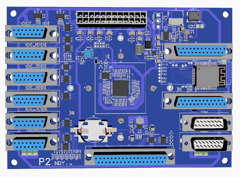
Nice looking board! I like the header/pin connectors for your auxiliary boards. Connectors seem to be the most expensive components of a board design now days! Your design looks a bit like my Indy P2 ( attached ) I got involved with other projects so once the final P2 was available I was off on other projects and never got any boards made. I'm curious about your CNC code, Did you write your own linear interpolative functions or did you use the code I uploaded as a start? If so, I'd love to see what you've done with it. I've had 6 axis code working for YEARS in the P1, however my P1 code only loaded one set of 6 axis GO variables at a time, It did the calculations then the movement function. This works fine with most of the things I do with CNC, but that millisecond delay at the "Figure it out" stage poses some difficulty with faster machines. With the P2, I was separating the "figure it out" code from the "Go" code to let one cog be calculating the next move and get rid of the millisecond delay at the beginning of each move. My next upgrade was going to be a third cog doing DC motor drive. Are you working on anything like this?
I won't say it's a "No Brainer" but it does seem like a next step in the design. Several years ago I was working with a company working on an axial flux DC motor. The P1 was doing the 5 axis phase coil control. A 4th cog might easily be doing something like this. Just wondering if you have it in the works? ![]
Anyway, nice board! good luck with it!
Sorry for not responding. I have some really strange computer problems, similar to those Chip had with Pnut and Propeller tool some time ago. Microsoft defender complains about my compiled binaries containing a Wacatac virus. But no virus scanner finds anything on my hard disk except for the binaries my compiler produces. Either a false alarm or a really clever virus.
My interpolator is not strictly linear. Ramp computation (velocity profile) and trajectory comutation (position coordinates) are completely seperated. The PC calculates the trajectory and the P2 calculates the velocity. Acceleration and deceleration is independent of G-code lines and linear segments. The acceleration ramp can reach across multiple line segments. The P2 doesn't even know where an individual line segment starts and ends. It just processes a stream of position+velocity vectors (n coordinates each plus one max. velocity for that point).
I'm currently working on porting the step/dir signal generator code from the P1 to the P2. On the P1 memory space was very restricted so I could only use 16 bit for the coordinates and velocity values. I managed to squeeze two axes into one cog by swapping high and low words of the cog ram so that a 256 word ring buffer for filtering fits in the cog while still having enough space for the code. This required tricky optimizations and overwriting of the parts of the code that were not necessary anymore after initialization. Thus, the code looks ugly and is nearly impossible to maintain. I'll better write re-write it completely from scratch for the P2.
Here, things are much more relaxed. Due to the unlimited number of NCO counters in the smart pins and the much higher computing power one cog can handle nearly any number of axes. A 1ms time slice for filtering and frequency calculations means 200,000 clocks @200MHz or 20,000 clocks per one of say 10 axes which is plenty.
I won't post the code, at least not for now. But if anybody is interested, here is how it works:
The caller/application places new positions of all axes into the array of nominal positions once per timer period (something ~1ms, usually). The cog processes theese positions and filters them to improve velocity and acceleration smoothness. The actual position therefore lags a bit behind and can be read from the actual position array.
Positions are counted in 1/16 step units, so a position delta of +/- 16 will output a full step cycle. 8 will output only half, i.e. a single rising or falling edge. This way, not
only step count but also phase can be controlled and jitter is reduced.
The moving flag indicates if at least one axis is still moving. This is important when waiting for standstill because some steps can still be in the filter queue even if the
nominal positions don't change.
The filtered velocity (delta pos) is used directly for the Y value to the NCO smart pin (step) and the sign for the direction pin.
Max. step frequency = 2MHz, clock frequency = 200MHz, NCO Y = 2^32 / 100 = 42.9*10^6
2MHz = 2000 full steps/ms = 32000 * 1/16 steps/ms (microsteps)
NCO calculation: Y = 2^32 * full steps / period = 2^28 * microsteps / period
2^28/period is a constant but we need the remainder of the division to avoid rounding errors summing up (phase creep). And we have a CORDIC unit so we do not optimize the
division out. Instead we add the remainder to the velocity of the next period. So the phase stays locked even if the period is not a power of 2 clocks.
Direction reversal needs special attention. We cannot change the DIR signal in the middle of a step cycle. Otherwise we would violate the step/dir setup/hold time requirement and risk loosing steps due to undefined direction. So we detect velocity sign changes one period ahead and add a "phase loan" so that the last step cycle in the old direction is always fully completed. The debt will be payed back in the next period in the new direction so that the overall error is zero. This assures that DIR changes only while STEP is low
and there are no short glitches or incomplete steps.
The filtering is needed to implement corner smoothing in a polynomial spline way. Most CAM systems output non-circular curved paths as sequence of G1 commands and this would cause strong vibrations due to acceleration spikes at the abrupt direction changes between the line segments. There are two filters, one for the velocity ramp to create an S-shaped velocity profile reducing jerks at the beginning and end of each motion. The second filter acts on each axis coordinate seperately turning sharp corners into parabolic curves. This reduces rattle while moving along the toolpath at constant velocity.
I look at my old servo/motion control code now and scratch my head a little. It's quite specialised as a gear-locked follower system but the worst is it's seriously lacking comments. My C skills were learnt on the job as the sole developer so it's not particularly full fleshed C either.
It was robust enough, although I did break some atomic rules, and I leant a lot back then and would publish it but ... I don't think its even close to readable.
Funny part is I know the customer got it checked out a couple of times by outside professionals. I imagine whoever looked at it must have said it lacked decent comments. He never said anything though, so not too sure what was being looked for.
PS: The business is long dead, cancer got him , so there's nothing left to develop for. There might still be a couple of the machines running but I doubt it. The CPU was a 486 on ISA card with LCD interface. And the I/O cards were ISA too. All Advantech gear. Pain to sort out a redesign once discontinued.
@evanh said:
Building profiles with S-curves and splines and other point adding maths is referred to as interpolation rather than filtering.
You're perfectly right. Interpolation is called what it does but filtering is the method how it's implemented. And it's a lot easier than doing the "real math" functions.
If you take a "brick wall" velocity profile, i.e. constant velocity from the start point to the end point and zero outside this interval and filter it twice with a moving average filter you get a decent S-curve without any polynomial or even a single multiplication required. And you don't need a square root to find out when you have to start the decelleration ramp.
FIR filters in general, yes. But a moving average filter is a two-tap FIR with coefficients of 1.0 and -1.0. You only need a ring buffer, one ADD and one SUB instruction and a final QDIV for scaling.
Huh, so you are applying that continuously for all profile generation, as a double integration, with simple previous and next target, all the time? What does that do to circles? Or are they just a lot more points?
EDIT: Hmm, no, it can't be that simple because basic targets are not time bound whereas the filter window is.
I don't understand what you mean with "target". As I explained in post #67, the P2 doesn't know about targets, line segments, circles, G-code lines or whatsoever. All it gets is a stream of coordinates. If the stream halts (no more data arrives) motion stops. The P2 knows how fast it can go depending on how much data is in the buffer. It's like driving in the fog. You must not drive faster as you could stop within the visibility range. So velocity is calculated from the F value in the G code and the buffer fill gauge, whichever is smaller. This velocity is then filtered with a moving average. The filter output is added to the interpolator pointer which advances through the buffer. The coordinates are then filtered again but for each axis seperately. This results in rounding of the corners.
The real art is to calculate the filter time constants (moving average window sizes) just right so they provide the right degree of rounding/smoothing but you don't loose too much precision (cutting corners).
Oh, I see, profile generation is actually done remotely. So the incoming data points are all evenly time spaced then, and the Prop2 is only filling the gaps.
Exactly. The PC sets some parameters like maximum velocity and max. acceleration before starting to transmit the stream. Then all position vectors are evenly time spaced projected for the max. velocity. The Propeller can slow down (if the buffer runs low or feed override is applied) by inserting more interpolated points between the buffer entires. So from the original stream with constant velocity a secondary "time stretched" stream is generated.
This is similar to the J.R.Kerr Networked Modular Control (NMC) and is the direction that I have been encouraging @DiverBob (Large Robot) to look at:
4.4.5 Path Control Mode
Path control mode, or Coordinated Motion Control (CMC) mode, is a special mode which allows the
host computer to easily coordinate the motion of several PIC-SERVO SC’s. The fundamental feature
of this mode is a path point buffer which stores a series of closely spaced motor goal points.
Coordination of multiple axes happens as follows:
1. The host (PC, etc.) calculates a series of closely spaced path points for one or more motors. The
idea is that each motor will move from one path point position to the next at a fixed time interval.
The multi-axis path is followed as all motors move from one path point to then next with the
exact same timing.
2. The host then downloads the sets path points to the individual PIC-SERVO SC controllers.
3. With a single group command, the host then starts all axes moving at the same time. Because of
the accurate crystal controlled timing of the PIC-SERVO SC, each motor will move synchronously
from one path point position to the next.
There are several important features to note about the path control mode. First, the path point buffer
can be continuously reloaded with new points while the motor is moving. The path point buffer can
hold up to about 4 seconds worth of path data, but if a desired motion is longer than that, new points
can be added to the buffer while moving to create continuous motions of unlimited length. For some
applications, it is desirable to only keep a small amount of data in the path point buffers at any time to
allow the host to change the path on-the-fly with a minimal delay.
The second important feature is that when the PIC-SERVO SC moves from path point to path point, it
doesn’t simply jerk from one point to the next - it creates a series of intermediate path points so that it
moves to the next path point with a constant velocity. Path points are calculated as the positions
where the motor should be at either 30, 60 or 120 Hz intervals. If, for example, the host created a set
of path points at 60 Hz intervals, the PIC-SERVO SC would calculate intermediate path points at
1953.125 Hz intervals. The effect of this intermediate smoothing with a multi-axis system is that all
of the axes will move from one path point to the next along a straight-line segment. This internal
smoothing allows path points calculated by the host to be spaced much more widely apart, and
requires much less data to be sent to the PIC-SERVO SC.
The obvious question in specifying path points at a relatively low frequency is: “how accurately will
the motors be able to follow my ideal path”. In fact, for typical applications, this error is very small.
For example, let’s say we have an X-Y table with two motors and we wish to move along a circular
path. If we were to move along a 1.0” diameter circle at a speed of 1.0” per second, and we
approximated the circle by a series of straight line segments spaced at 30 Hz intervals, the maximum
error between the straight lines and a true circle would be 0.00028”. If we switched to 60 Hz
intervals, the maximum error would drop to 0.000069”. Slowing down the motion or increasing the
radius of curvature would further increase the accuracy.
Path points are downloaded to the PIC-SERVO SC using the Add Path Points
command. With a single Add Path Points command, up to 7 path points can be downloaded to a
controller. Once all of the controllers have been loaded with their path point data, the Add Path Point
command, this time with no path point data, is issued to the entire group of controllers using a group
command. This causes all controllers to start executing the path at the same time.
While the path is running, it is useful to poll at least one of the controllers and have the number of
points remaining in the path point buffer returned in the status packet. The host can then add more
path points as needed, and also avoid overflowing the path point buffer, which can hold a maximum
of 128 path points.
When a path point is downloaded into the path point buffer, the position data also includes a bit
which specifies whether that path point should be reached in 33 milliseconds (30 Hz) or in 16.7
milliseconds (60 Hz). This allows the host, in the middle of a move, to use more closely spaced when
moving along a tightly radiused curve. While normally paths are run at 30 or 60 Hz, there is also a
fast path mode bit (which can be set using the I/O Control command) which allows the path to run at
60 or 120 Hz instead.
The number of axes of motion which can be coordinated is limited by the speed of the serial port
connection and by the path point rate. At a Baud rate of 115,200, it is possible to coordinate the
motions of up to about 16 axes when using a 30 Hz path point rate. At 60 or 120 Hz, the number of
axes drops to 8 or 4 respectively.
Latest update:
I've implemented the PASM driver for the VFD which generates 3-phase sine waves, handles the current sensor ADCs and does the Park transformation. I should be able to drive the PWM power stage and measure the current vector amplitude and phase angle, now. But before I do some real tests with some motor I have to modify my board a bit and add a gate for hardware overcurrent shutdown. Because of too much optimization I'm not able to shutdown the power stage fast enough by software. I feel better if this is hardwired, anyway.
@ManAtWork said:
Latest update:
I've implemented the PASM driver for the VFD which generates 3-phase sine waves, handles the current sensor ADCs and does the Park transformation. I should be able to drive the PWM power stage and measure the current vector amplitude and phase angle, now. But before I do some real tests with some motor I have to modify my board a bit and add a gate for hardware overcurrent shutdown. Because of too much optimization I'm not able to shutdown the power stage fast enough by software. I feel better if this is hardwired, anyway.
Pure sine waves, without any overmodulation? It seems like e.g. third harmonic injection would be really easy to do with the CORDIC.
EDIT: Oh, it seems the optimal way to do overmodulation is just to subtract the mean of the min and max of the three sine waves from each of the three sine waves. This gets you 2/sqrt(3) times as much power for a given maximum output voltage. I never realized generating the fancy waveforms was that simple.
The VFD of this controller is intended to be used with induction motors (asynchronous, squirrel cage) what most spindle motors are. They usually show very little cogging and can run very smoothly on pure sine waves. Harmonic injection is useful for permanent magnet synchronous motors which have a sub-optimum magnetic design with square neodymium magnets. They show heavy cogging and detent torque and would benefit from adding third harmonic to run smoothly. I think the best way to implement this would be to let the motor free-wheel and record a look-up table of the back EMF of the motor because each motor design behaves differently.
@Electrodude said:
EDIT: Oh, it seems the optimal way to do overmodulation is just to subtract the mean of the min and max of the three sine waves from each of the three sine waves. This gets you 2/sqrt(3) times as much power for a given maximum output voltage. I never realized generating the fancy waveforms was that simple.
Yes I already do that. It's actually required to get an RMS output voltage that comes close to the input voltage. If you want to get the maximum power out of a motor you can also simply use clipping. The sine waves then aproach a trapezoid shape and the RMS voltage gets higher than the input voltage. However, you have to be careful. Some motos don't like this. If the coil currents of a delta-configuration winding also have third overtone components there are circulating currents that heat up the motor and don't produce torque. That's because all third harmonics have the same phase even if the base frquencies have 120° phase shift.
BTW, for most CNC applications you don't need max spindle power at high RPMs. Spindle motors are usually totally over-powered. Small routers have 1-2kW and big milling machines or lathes have 15kW or more. The reason for this is to save the gear. For tools with larger diameter you need max torque al low RPM and for tiny drills you need high RPM but low torque, but almost never high torque and high RPM both at once. 0.5kW would be enough for most jobs if you had "automatic transmission".
A good vector control algorithm helps to get high torque at low frequencies and is much more important than max power at high RPM where the voltage is close to maximum. The problem is that at low frequencies and idle the voltage needs to be also low to avoid saturating the iron core and heat up the windings. When load is applied you need to increase voltage and frequency just the right amount to compensate slip and voltage drop due to resistive losses. In reality it's even more complicated. You need D-current for rotor excitation but only the Q component produces torque. If you don't have an encoder you can only guess the exact rotor position and orientation of the field vector.
There is one reason for having high torque and high RPM on the spindle - To get steep Acceleration. Management love to hear those working hard to rapidly ramp the RPMs on those fine cuts. See the lights dim in the workshop. The heat waves pouring out the rear of the control cabinet.
Acceleration is easy. Just ramp up frequency and voltage as hard as possible just not to trip the fuses. Decelleration is a bit more complicated. You need to get rid of the kinetic energy and avoid exploding the DC bus caps. Big bleeding resistors and brake chopper IGBT cost money.
Yes. I know there are modules with IGBTs and gate drivers in one package. Those for washing machines or air conditioners are affordable. But the change from year to year and become obsolete quite soon. I've learned in the pandemic that it's better not to be dependent on very special parts that are only available from a single manufacturer. Single IGBTs are available from many manufacturers and I can easily replace them with newer types if necessary. I use the same module as for this project. 7 IGBTs (3 half bridges and one brake chopper) are mounted on an aluminium core PCB.
The DC bus supply consists of only a rectifier, some big electrolytic caps and a soft start circuit (power resistor to slowly charge the caps and then shunt the resistor with a relay).
I'll only support two sizes for the cost sensitive machines. The basic version will run spindles up to 1.5kW (230V 5A RMS). For bigger spindles up to 2.2 or maybe 3kW I just mount a bigger heatsink, more caps and I replace the 6A current sensors with 12A types. Everything with more power requires a 3 phase 400V supply anyway. Only <10% of the machines require this so it doesn't make sense to provide many different sizes as a few $ more makes no big difference. It's better to buy an external VFD for that cases.
1 step forward: Parameter storage with the flash file system works.
1 step backward: I have to debug the OLED display driver, again. It somehow collides with the printf() and debug() output to the terminal.
Edit: I first thought that the display driver screwed up debug() or printf(). There was indeed a false call to putchar() but removing it didn't change anything. But my ethernet driver and the display driver both used the same I2C pins but with different I2C drivers. No good idea. One of the drivers left the pins in a false state, I think. I changed the order in which the init routines are called and now it works reliably. Still a bit suspicious but my debugging motivation for today is used up.


Comments
Hmmm, Just a few minutes of why not try/what could I do/how can I make it dumb_$$ proof, can be a deep and twisty rabbit hole to go down. Everybody observing this thread thinking why not try to ...... should try it as a mental exercise. Figure out what you would do, how practical, how expensive and then how easily defeated anyway....
I like that particular idea from ManAtWork. It's not actually adding to the safety circuits per-se but it does encourage the good practise of verifying the safeties are functioning.
I totally agree with @ManAtWork when he says:
It deserves a new thread.
That aside, my take on the subject is this. Safety can never be guaranteed but can always be improved. Any idea that results in increased safety should be evaluated but not every perfectly good idea can be reasonably implemented in real life (for cost, inadequate regulations, company policies etc). I could go on for a while with these but you get the idea. Peoples' stupidity and ignorance knows no limits.
I have some real life stories to tell on the subject, really crazy stuff so if there is a new thread or a slight encouragement or permission from this topic's initiator, I can share them here as well.
If your just selling a CNC control you don't think you have much liability, as long as your lawyer words the disclaimer properly in the instructions, example that you have no control on how an end user installs and uses the control, and that the end user accepts all liability by using and installing the product. That's only my opinion check with your own legal team.
Hey MANATWORK,
Nice looking board! I like the header/pin connectors for your auxiliary boards. Connectors seem to be the most expensive components of a board design now days! Your design looks a bit like my Indy P2 ( attached ) I got involved with other projects so once the final P2 was available I was off on other projects and never got any boards made. I'm curious about your CNC code, Did you write your own linear interpolative functions or did you use the code I uploaded as a start? If so, I'd love to see what you've done with it. I've had 6 axis code working for YEARS in the P1, however my P1 code only loaded one set of 6 axis GO variables at a time, It did the calculations then the movement function. This works fine with most of the things I do with CNC, but that millisecond delay at the "Figure it out" stage poses some difficulty with faster machines. With the P2, I was separating the "figure it out" code from the "Go" code to let one cog be calculating the next move and get rid of the millisecond delay at the beginning of each move. My next upgrade was going to be a third cog doing DC motor drive. Are you working on anything like this?
I won't say it's a "No Brainer" but it does seem like a next step in the design. Several years ago I was working with a company working on an axial flux DC motor. The P1 was doing the 5 axis phase coil control. A 4th cog might easily be doing something like this. Just wondering if you have it in the works? ![]
Anyway, nice board! good luck with it!
Ken
Sorry for not responding. I have some really strange computer problems, similar to those Chip had with Pnut and Propeller tool some time ago. Microsoft defender complains about my compiled binaries containing a Wacatac virus. But no virus scanner finds anything on my hard disk except for the binaries my compiler produces. Either a false alarm or a really clever virus.
My interpolator is not strictly linear. Ramp computation (velocity profile) and trajectory comutation (position coordinates) are completely seperated. The PC calculates the trajectory and the P2 calculates the velocity. Acceleration and deceleration is independent of G-code lines and linear segments. The acceleration ramp can reach across multiple line segments. The P2 doesn't even know where an individual line segment starts and ends. It just processes a stream of position+velocity vectors (n coordinates each plus one max. velocity for that point).
I'm currently working on porting the step/dir signal generator code from the P1 to the P2. On the P1 memory space was very restricted so I could only use 16 bit for the coordinates and velocity values. I managed to squeeze two axes into one cog by swapping high and low words of the cog ram so that a 256 word ring buffer for filtering fits in the cog while still having enough space for the code. This required tricky optimizations and overwriting of the parts of the code that were not necessary anymore after initialization. Thus, the code looks ugly and is nearly impossible to maintain. I'll better write re-write it completely from scratch for the P2.
Here, things are much more relaxed. Due to the unlimited number of NCO counters in the smart pins and the much higher computing power one cog can handle nearly any number of axes. A 1ms time slice for filtering and frequency calculations means 200,000 clocks @200MHz or 20,000 clocks per one of say 10 axes which is plenty.
I won't post the code, at least not for now. But if anybody is interested, here is how it works:
The caller/application places new positions of all axes into the array of nominal positions once per timer period (something ~1ms, usually). The cog processes theese positions and filters them to improve velocity and acceleration smoothness. The actual position therefore lags a bit behind and can be read from the actual position array.
Positions are counted in 1/16 step units, so a position delta of +/- 16 will output a full step cycle. 8 will output only half, i.e. a single rising or falling edge. This way, not
only step count but also phase can be controlled and jitter is reduced.
The moving flag indicates if at least one axis is still moving. This is important when waiting for standstill because some steps can still be in the filter queue even if the
nominal positions don't change.
The filtered velocity (delta pos) is used directly for the Y value to the NCO smart pin (step) and the sign for the direction pin.
Max. step frequency = 2MHz, clock frequency = 200MHz, NCO Y = 2^32 / 100 = 42.9*10^6
2MHz = 2000 full steps/ms = 32000 * 1/16 steps/ms (microsteps)
NCO calculation: Y = 2^32 * full steps / period = 2^28 * microsteps / period
2^28/period is a constant but we need the remainder of the division to avoid rounding errors summing up (phase creep). And we have a CORDIC unit so we do not optimize the
division out. Instead we add the remainder to the velocity of the next period. So the phase stays locked even if the period is not a power of 2 clocks.
Direction reversal needs special attention. We cannot change the DIR signal in the middle of a step cycle. Otherwise we would violate the step/dir setup/hold time requirement and risk loosing steps due to undefined direction. So we detect velocity sign changes one period ahead and add a "phase loan" so that the last step cycle in the old direction is always fully completed. The debt will be payed back in the next period in the new direction so that the overall error is zero. This assures that DIR changes only while STEP is low
and there are no short glitches or incomplete steps.
The filtering is needed to implement corner smoothing in a polynomial spline way. Most CAM systems output non-circular curved paths as sequence of G1 commands and this would cause strong vibrations due to acceleration spikes at the abrupt direction changes between the line segments. There are two filters, one for the velocity ramp to create an S-shaped velocity profile reducing jerks at the beginning and end of each motion. The second filter acts on each axis coordinate seperately turning sharp corners into parabolic curves. This reduces rattle while moving along the toolpath at constant velocity.
Building profiles with S-curves and splines and other point adding maths is referred to as interpolation rather than filtering.
I look at my old servo/motion control code now and scratch my head a little. It's quite specialised as a gear-locked follower system but the worst is it's seriously lacking comments. My C skills were learnt on the job as the sole developer so it's not particularly full fleshed C either.
It was robust enough, although I did break some atomic rules, and I leant a lot back then and would publish it but ... I don't think its even close to readable.
Funny part is I know the customer got it checked out a couple of times by outside professionals. I imagine whoever looked at it must have said it lacked decent comments. He never said anything though, so not too sure what was being looked for.
PS: The business is long dead, cancer got him , so there's nothing left to develop for. There might still be a couple of the machines running but I doubt it. The CPU was a 486 on ISA card with LCD interface. And the I/O cards were ISA too. All Advantech gear. Pain to sort out a redesign once discontinued.
You're perfectly right. Interpolation is called what it does but filtering is the method how it's implemented. And it's a lot easier than doing the "real math" functions.
If you take a "brick wall" velocity profile, i.e. constant velocity from the start point to the end point and zero outside this interval and filter it twice with a moving average filter you get a decent S-curve without any polynomial or even a single multiplication required. And you don't need a square root to find out when you have to start the decelleration ramp.
FIR filters are horribly expensive on processing time. I guess if you've got lots of spare MIPs ...
FIR filters in general, yes. But a moving average filter is a two-tap FIR with coefficients of 1.0 and -1.0.") You only need a ring buffer, one ADD and one SUB instruction and a final QDIV for scaling.
You only need a ring buffer, one ADD and one SUB instruction and a final QDIV for scaling.
Huh, so you are applying that continuously for all profile generation, as a double integration, with simple previous and next target, all the time? What does that do to circles? Or are they just a lot more points?
EDIT: Hmm, no, it can't be that simple because basic targets are not time bound whereas the filter window is.
I don't understand what you mean with "target". As I explained in post #67, the P2 doesn't know about targets, line segments, circles, G-code lines or whatsoever. All it gets is a stream of coordinates. If the stream halts (no more data arrives) motion stops. The P2 knows how fast it can go depending on how much data is in the buffer. It's like driving in the fog. You must not drive faster as you could stop within the visibility range. So velocity is calculated from the F value in the G code and the buffer fill gauge, whichever is smaller. This velocity is then filtered with a moving average. The filter output is added to the interpolator pointer which advances through the buffer. The coordinates are then filtered again but for each axis seperately. This results in rounding of the corners.
The real art is to calculate the filter time constants (moving average window sizes) just right so they provide the right degree of rounding/smoothing but you don't loose too much precision (cutting corners).
Oh, I see, profile generation is actually done remotely. So the incoming data points are all evenly time spaced then, and the Prop2 is only filling the gaps.
Exactly. The PC sets some parameters like maximum velocity and max. acceleration before starting to transmit the stream. Then all position vectors are evenly time spaced projected for the max. velocity. The Propeller can slow down (if the buffer runs low or feed override is applied) by inserting more interpolated points between the buffer entires. So from the original stream with constant velocity a secondary "time stretched" stream is generated.
Next milestone reached: Step/Dir signal generator debugged, at least in single-step mode. Real time performance has still to be tested.
This is similar to the J.R.Kerr Networked Modular Control (NMC) and is the direction that I have been encouraging @DiverBob (Large Robot) to look at:
Craig
Latest update:
I've implemented the PASM driver for the VFD which generates 3-phase sine waves, handles the current sensor ADCs and does the Park transformation. I should be able to drive the PWM power stage and measure the current vector amplitude and phase angle, now. But before I do some real tests with some motor I have to modify my board a bit and add a gate for hardware overcurrent shutdown. Because of too much optimization I'm not able to shutdown the power stage fast enough by software. I feel better if this is hardwired, anyway.
Pure sine waves, without any overmodulation? It seems like e.g. third harmonic injection would be really easy to do with the CORDIC.
EDIT: Oh, it seems the optimal way to do overmodulation is just to subtract the mean of the min and max of the three sine waves from each of the three sine waves. This gets you 2/sqrt(3) times as much power for a given maximum output voltage. I never realized generating the fancy waveforms was that simple.
The VFD of this controller is intended to be used with induction motors (asynchronous, squirrel cage) what most spindle motors are. They usually show very little cogging and can run very smoothly on pure sine waves. Harmonic injection is useful for permanent magnet synchronous motors which have a sub-optimum magnetic design with square neodymium magnets. They show heavy cogging and detent torque and would benefit from adding third harmonic to run smoothly. I think the best way to implement this would be to let the motor free-wheel and record a look-up table of the back EMF of the motor because each motor design behaves differently.
Yes I already do that. It's actually required to get an RMS output voltage that comes close to the input voltage. If you want to get the maximum power out of a motor you can also simply use clipping. The sine waves then aproach a trapezoid shape and the RMS voltage gets higher than the input voltage. However, you have to be careful. Some motos don't like this. If the coil currents of a delta-configuration winding also have third overtone components there are circulating currents that heat up the motor and don't produce torque. That's because all third harmonics have the same phase even if the base frquencies have 120° phase shift.
BTW, for most CNC applications you don't need max spindle power at high RPMs. Spindle motors are usually totally over-powered. Small routers have 1-2kW and big milling machines or lathes have 15kW or more. The reason for this is to save the gear. For tools with larger diameter you need max torque al low RPM and for tiny drills you need high RPM but low torque, but almost never high torque and high RPM both at once. 0.5kW would be enough for most jobs if you had "automatic transmission".
A good vector control algorithm helps to get high torque at low frequencies and is much more important than max power at high RPM where the voltage is close to maximum. The problem is that at low frequencies and idle the voltage needs to be also low to avoid saturating the iron core and heat up the windings. When load is applied you need to increase voltage and frequency just the right amount to compensate slip and voltage drop due to resistive losses. In reality it's even more complicated. You need D-current for rotor excitation but only the Q component produces torque. If you don't have an encoder you can only guess the exact rotor position and orientation of the field vector.
Yippee! Motor is running: https://youtube.com/shorts/FtOpPwyWh5w
There is one reason for having high torque and high RPM on the spindle - To get steep Acceleration. Management love to hear those working hard to rapidly ramp the RPMs on those fine cuts. See the lights dim in the workshop. The heat waves pouring out the rear of the control cabinet.
Acceleration is easy. Just ramp up frequency and voltage as hard as possible just not to trip the fuses. Decelleration is a bit more complicated. You need to get rid of the kinetic energy and avoid exploding the DC bus caps. Big bleeding resistors and brake chopper IGBT cost money.
Are you going to make your own 3 phase h bridge driver?
Yes. I know there are modules with IGBTs and gate drivers in one package. Those for washing machines or air conditioners are affordable. But the change from year to year and become obsolete quite soon. I've learned in the pandemic that it's better not to be dependent on very special parts that are only available from a single manufacturer. Single IGBTs are available from many manufacturers and I can easily replace them with newer types if necessary. I use the same module as for this project. 7 IGBTs (3 half bridges and one brake chopper) are mounted on an aluminium core PCB.
Nice... and the dc bus power supply?
And for several sizes to accomidate different size induction motors?
The DC bus supply consists of only a rectifier, some big electrolytic caps and a soft start circuit (power resistor to slowly charge the caps and then shunt the resistor with a relay).
I'll only support two sizes for the cost sensitive machines. The basic version will run spindles up to 1.5kW (230V 5A RMS). For bigger spindles up to 2.2 or maybe 3kW I just mount a bigger heatsink, more caps and I replace the 6A current sensors with 12A types. Everything with more power requires a 3 phase 400V supply anyway. Only <10% of the machines require this so it doesn't make sense to provide many different sizes as a few $ more makes no big difference. It's better to buy an external VFD for that cases.
1 step forward: Parameter storage with the flash file system works.")

1 step backward: I have to debug the OLED display driver, again. It somehow collides with the printf() and debug() output to the terminal.
Edit: I first thought that the display driver screwed up debug() or printf(). There was indeed a false call to putchar() but removing it didn't change anything. But my ethernet driver and the display driver both used the same I2C pins but with different I2C drivers. No good idea. One of the drivers left the pins in a false state, I think. I changed the order in which the init routines are called and now it works reliably. Still a bit suspicious but my debugging motivation for today is used up.