@ManAtWork said:
I'm not sure what this means. What is the "data sequence within the individual bytes"? In the 4-pin modes there are no bytes but nibbles. I would expect that a longword $12345678 is shifted out as nibbles with the $8 nibble first and $1 last in normal mode and $1 first and $8 last in alternate mode. But this is definitely not the case.
@Wuerfel_21 said:
Alternate mode would do 7 8 5 6 3 4 1 2 then. Which would track with how the hub memory read/write modes work.
That's actually correct. So alternate mode swaps the nibbles of each byte but doesn't mirror the byte or nibble order in the whole immediate operand longword. After having understood this everything is clear and it explains why there is no alternate bit in the 8, 16 and 32 pin modes. But I was fooled by the confirmation bias effect when I had to sort out the big/little-endian byte order and was expecting the wrong thing. I've added a note to the silicon docs for clarification.
CON
  modeSQIC = X_IMM_8X4_4DAC1 + X_PINS_ON + X_ALT_ON + 6    ' streamer command TX 3 bytes = 6 nibbles

...
PUB WriteSqi (regAdr, data) | cs, sclk, sio0, sio1, all, mode
' write one register via SQI
  longmove (@cs, @pinCS, 6)
  ORG
    movbyts  regAdr,#%11_10_00_01 ' swap bytes, address is big-endian
    rolbyte  regAdr,cmdWrite,#0   ' command first
    setxfrq  ##XCLKDIV
    drvl     all
    drvl     cs
    wxpin    #2,sclk              ' sysclk/4
    xinit    mode,regAdr          ' start streamer
    wypin    #28,sclk             ' start clock, 14 pulses
    setword  mode,#8,#0           ' 8 instead of 6 nibbles
    xcont    mode,data
    waitxfi
    dirl     all
    drvh     cs
  END
The timing is just right. At _clkfreq = 200MHz the SPI clock is 50Mhz, data setup time is 15ns and hold time 5ns.
I thought I could make that a symetrical setup/hold of 10/10ns by using the P_SYNC_IO option for the data pins. But unfortunatelly, that doesn't work. The streamer output doesn't seem to be routed through the flipflops but directly to the pins. BTW, although my scope claims to have 2Gsamples and 200MHz bandwidth it struggles to catch the 3rd overtone and displays the 50MHz square wave signal as pure sine wave.
I had some problems with the LAN9252 which refused to respond at the SPI interface. It turnes out that the information given in the data sheet about the mapping of the boot EEPROM contents to the registers is quite useless. It is mandatory that the chip is programmed with the EEPROM programming tool provided by Beckhoff otherwise it doesn't work. Fortunatelly, after the XML file is compiled to a hex or binary file that can later be copied directly to the EEPROM as often if you want. To be fair, I also had some problems with my board and soldering joints...
Anyway, I've managed to get it to work. I can now poll until the chip is ready, switch from SPI (25MHz, single bit) to QSPI mode (50MHz, 4 bits) and read/write a single or multiple registers.
The demo reads the BYTE_TEST register two times over SPI and two times over QSPI. Then it writes the Timer register and reads it back. Then it does a block read of the chip ID and the IRQ config registers.
Still should pair up the DIRH + WYPIN for sclk. I guess I need to document that better in my source code. Those two instructions are best together in that order. At the moment, you're relying too much on coincidence of multiple smartpin cycles. If any code or ratio in there gets changed you'll be taking stabs at the ideal leadin delay to compensate.
Oh, a minor optimisation: The WRFAST in ReadBlock can be issued up at the head of the assembly. Streamer immediate mode operations don't consume FIFO data, therefore the FIFO can be prep'd earlier. In doing so, the restarting of the SCLK can also be ditched, making the tx-rx turnaround transition be gapless clocking.
@evanh said:
Oh, a minor optimisation: The WRFAST in ReadBlock can be issued up at the head of the assembly. Streamer immediate mode operations don't consume FIFO data, therefore the FIFO can be prep'd earlier.
Doing the WRFAST at the very beginning would make the overall execution time longer. Embedding it somewhere where the P2 is waiting anyway doesn't take extra time. What is the worst case delay for WRFAST? I think it was something around 13 cycles. The waitxfi waits at least 20 cycles so that should be OK. Or is WRFAST even faster because opposed to RDFAST it doesn't fave to wait for the FIFO to be filled up?
In doing so, the restarting of the SCLK can also be ditched, making the tx-rx turnaround transition be gapless clocking.
Yes I think there is some room for optimization. I just wanted to be careful because the streamer needs different phase adjustment for input vs. output. Adding some cycles delay with a short XCONT leadin,#0 is easy but the opposite is impossible. Now that I know that the input leadin is longer than the output leadin we could let the clock run continously and just add the delta delay.
@ManAtWork said:
What is the worst case delay for WRFAST? I think it was something around 13 cycles. The waitxfi waits at least 20 cycles so that should be OK. Or is WRFAST even faster because opposed to RDFAST it doesn't fave to wait for the FIFO to be filled up?
Execution time is 2 sysclock ticks for both RDFAST and WRFAST when bit31 of D operand is set. FIFO setup happens concurrently post-instruction.
As for how long a FIFO setup takes, it is only extended by write flush time. Since there is not typically anything to flush nor any waiting on the hub it'll be just 3 ticks (including instruction execution) for WRFAST, 10..17 ticks (instruction execution + hub rotation + prefetching) for RDFAST.
PS: FIFO writes are auto-flushed to hubRAM on a next-free-slot basis. Data will never be buffered more than 8 ticks and will usually result in singles written. As such, FIFO writes can really mess with timing of Cog direct accesses to hubRAM.
@evanh said:
PS: FIFO writes are auto-flushed to hubRAM on a next-free-slot basis. Data will never be buffered more than 8 ticks and will usually result in singles written. As such, FIFO writes can really mess with timing of Cog direct accesses to hubRAM.
The worst case there is getting blocked for 32 additional cycles, right? (assuming single non-block access). When the FIFO writes the same slice 4 times in a row due to receiving bytes at sysclk/8.
I think so, yes. The Streamer/FIFO can write consecutive bytes one at a time to the same longword. Those of course all sit at the same slice so will probably block a Cog direct access repeatedly when timed like that.
EDIT: That does clear up why my byte sized streamer testing got the worst results. Shortword was worse interference than longword, and byte was worse still. I remember scratching my head at the time.
Tony and I empirically made up a formula to calculate the impact too. It fitted, but I didn't really figure out why at the time.
So nibbles at sysclk/4 also produce the worst case of 1 byte every 8 clocks. But it should be fine with my code because Prop Tool and FlexProp copy short ASM code blocks to cog RAM, AFAIK.
@ManAtWork said:
So nibbles at sysclk/4 also produce the worst case of 1 byte every 8 clocks.
Yes
But it should be fine with my code because Prop Tool and FlexProp copy short ASM code blocks to cog RAM, AFAIK.
You can't have hubexec and streamer DMA at the same time, anyways. They both use the FIFO unit. So the streamer-using code must be in cog/lut memory to begin with (ORG/END-type inline ASM blocks guarantee this)
No errors. Maybe lacking some info. What the "alternate" order is exactly.
And internal FIFO behaviour needs documented. There is quite a few hardware functions that could do with more fleshing out. Like the I/O staging diagram for the Cogs, also should have one for Smartpins too.
No error. I've just expected something different when I first read the docs. After understanding the purpose of the alternate bit it's clear, now.
Modes which shift data use bits bottom-first, by default. Some of these modes have the %a bit in D[16] to reorder the data sequence within the individual bytes to top-first when %a = 1.
I've already added a note to the streamer docs (page 34 of the silicon doc):
This needs clarification. Example: In 4-pin mode the nibbles of each byte are swapped. If an immediate S operand of #$87654321 is given then in normal mode the output sequence is 1, 2, 3... etc. and in alternate mode it's 2, 1, 4, 3... and not 8,7,6... or 4, 8, 2, C... (bits reversed) as one might expect.
@cgracey Have I already said that I'd really appreciate if the P2 hardware and assembler manuals would be finally completed? (nudge, nudge)
The P1 had (errr, still has) so excellent documentation with lots of examples and hints. I especially like the Propeller manual (Spin + Assembler) and the Education Kit Labs. It is important to not only write down how the chip behaves. Everything is a lot easier to understand if the purpose of the features are mentioned and examples are given. If you then have to solve a particular problem you remember "ah, there was something that could be used for this purpose" and can look it up in the manual. The existing documentation for the P2 is already quite good but there are important parts missing like the streamer.


Comments
That's actually correct. So alternate mode swaps the nibbles of each byte but doesn't mirror the byte or nibble order in the whole immediate operand longword. After having understood this everything is clear and it explains why there is no alternate bit in the 8, 16 and 32 pin modes. But I was fooled by the confirmation bias effect when I had to sort out the big/little-endian byte order and was expecting the wrong thing. I've added a note to the silicon docs for clarification.
This makes the code even shorter:
CON modeSQIC = X_IMM_8X4_4DAC1 + X_PINS_ON + X_ALT_ON + 6 ' streamer command TX 3 bytes = 6 nibbles ... PUB WriteSqi (regAdr, data) | cs, sclk, sio0, sio1, all, mode ' write one register via SQI longmove (@cs, @pinCS, 6) ORG movbyts regAdr,#%11_10_00_01 ' swap bytes, address is big-endian rolbyte regAdr,cmdWrite,#0 ' command first setxfrq ##XCLKDIV drvl all drvl cs wxpin #2,sclk ' sysclk/4 xinit mode,regAdr ' start streamer wypin #28,sclk ' start clock, 14 pulses setword mode,#8,#0 ' 8 instead of 6 nibbles xcont mode,data waitxfi dirl all drvh cs ENDThe timing is just right. At _clkfreq = 200MHz the SPI clock is 50Mhz, data setup time is 15ns and hold time 5ns.
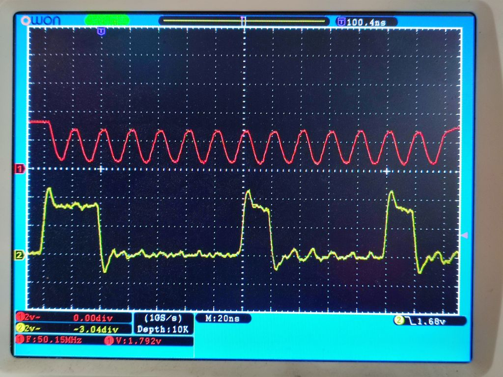
I thought I could make that a symetrical setup/hold of 10/10ns by using the P_SYNC_IO option for the data pins. But unfortunatelly, that doesn't work. The streamer output doesn't seem to be routed through the flipflops but directly to the pins. BTW, although my scope claims to have 2Gsamples and 200MHz bandwidth it struggles to catch the 3rd overtone and displays the 50MHz square wave signal as pure sine wave.
P_SYNC_IO absolutely works on all logic pin functions. Only way to bypass is by using the ADC or DAC functions.
You're most likely running into the smartpin alignment issue instead. My exact code for aligning the streamer to the clock gen has its benefits.
Ah, you mean the code snippet in post #8? I haven't understood it when you posted it but now it's clear. Thanks!
Yep, post #8. Yeah, having some experience first will definitely help.
I had some problems with the LAN9252 which refused to respond at the SPI interface. It turnes out that the information given in the data sheet about the mapping of the boot EEPROM contents to the registers is quite useless. It is mandatory that the chip is programmed with the EEPROM programming tool provided by Beckhoff otherwise it doesn't work. Fortunatelly, after the XML file is compiled to a hex or binary file that can later be copied directly to the EEPROM as often if you want. To be fair, I also had some problems with my board and soldering joints...
Anyway, I've managed to get it to work. I can now poll until the chip is ready, switch from SPI (25MHz, single bit) to QSPI mode (50MHz, 4 bits) and read/write a single or multiple registers.
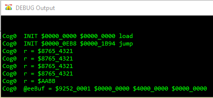
The demo reads the BYTE_TEST register two times over SPI and two times over QSPI. Then it writes the Timer register and reads it back. Then it does a block read of the chip ID and the IRQ config registers.
Still should pair up the DIRH + WYPIN for
sclk. I guess I need to document that better in my source code. Those two instructions are best together in that order. At the moment, you're relying too much on coincidence of multiple smartpin cycles. If any code or ratio in there gets changed you'll be taking stabs at the ideal leadin delay to compensate.Oh, a minor optimisation: The WRFAST in
ReadBlockcan be issued up at the head of the assembly. Streamer immediate mode operations don't consume FIFO data, therefore the FIFO can be prep'd earlier. In doing so, the restarting of the SCLK can also be ditched, making the tx-rx turnaround transition be gapless clocking.Doing the WRFAST at the very beginning would make the overall execution time longer. Embedding it somewhere where the P2 is waiting anyway doesn't take extra time. What is the worst case delay for WRFAST? I think it was something around 13 cycles. The waitxfi waits at least 20 cycles so that should be OK. Or is WRFAST even faster because opposed to RDFAST it doesn't fave to wait for the FIFO to be filled up?
Yes I think there is some room for optimization. I just wanted to be careful because the streamer needs different phase adjustment for input vs. output. Adding some cycles delay with a short XCONT leadin,#0 is easy but the opposite is impossible. Now that I know that the input leadin is longer than the output leadin we could let the clock run continously and just add the delta delay.
Execution time is 2 sysclock ticks for both RDFAST and WRFAST when bit31 of D operand is set. FIFO setup happens concurrently post-instruction.
As for how long a FIFO setup takes, it is only extended by write flush time. Since there is not typically anything to flush nor any waiting on the hub it'll be just 3 ticks (including instruction execution) for WRFAST, 10..17 ticks (instruction execution + hub rotation + prefetching) for RDFAST.
PS: FIFO writes are auto-flushed to hubRAM on a next-free-slot basis. Data will never be buffered more than 8 ticks and will usually result in singles written. As such, FIFO writes can really mess with timing of Cog direct accesses to hubRAM.
The worst case there is getting blocked for 32 additional cycles, right? (assuming single non-block access). When the FIFO writes the same slice 4 times in a row due to receiving bytes at sysclk/8.
I think so, yes. The Streamer/FIFO can write consecutive bytes one at a time to the same longword. Those of course all sit at the same slice so will probably block a Cog direct access repeatedly when timed like that.
EDIT: That does clear up why my byte sized streamer testing got the worst results. Shortword was worse interference than longword, and byte was worse still. I remember scratching my head at the time.
Tony and I empirically made up a formula to calculate the impact too. It fitted, but I didn't really figure out why at the time.
So nibbles at sysclk/4 also produce the worst case of 1 byte every 8 clocks. But it should be fine with my code because Prop Tool and FlexProp copy short ASM code blocks to cog RAM, AFAIK.
Yes
You can't have hubexec and streamer DMA at the same time, anyways. They both use the FIFO unit. So the streamer-using code must be in cog/lut memory to begin with (ORG/END-type inline ASM blocks guarantee this)
So, is it still suspected that there is an error in the docs or silicon?
At least, some clarification in the docs is needed.
No errors. Maybe lacking some info. What the "alternate" order is exactly.
And internal FIFO behaviour needs documented. There is quite a few hardware functions that could do with more fleshing out. Like the I/O staging diagram for the Cogs, also should have one for Smartpins too.
No error. I've just expected something different when I first read the docs. After understanding the purpose of the alternate bit it's clear, now.
I've already added a note to the streamer docs (page 34 of the silicon doc):
@cgracey Have I already said that I'd really appreciate if the P2 hardware and assembler manuals would be finally completed?")
") (nudge, nudge)
(nudge, nudge)
The P1 had (errr, still has) so excellent documentation with lots of examples and hints. I especially like the Propeller manual (Spin + Assembler) and the Education Kit Labs. It is important to not only write down how the chip behaves. Everything is a lot easier to understand if the purpose of the features are mentioned and examples are given. If you then have to solve a particular problem you remember "ah, there was something that could be used for this purpose" and can look it up in the manual. The existing documentation for the P2 is already quite good but there are important parts missing like the streamer.