

M6 - bit of SMART NCO Frequency
 Christof Eb.
Posts: 1,597
Christof Eb.
Posts: 1,597
Hi,
I am trying to using some code from @FredBlais to output I2S at a MAX98357A.
https://github.com/speccy88/TAQOZ/blob/master/src/forth/audio/WAV-I2S.FTH
It sets a pin to NCO-Frequency mode and -as far as I understand- tries to output the inverted signal by setting bit14 = M6.
(Sorry for the FORTH syntax.)
%1_00110_0          := #NCO_FREQ
1 14 << NCO_FREQ OR     := #NegNCO_FREQ
...
*BCLK PIN #NegNCO_FREQ WRPIN
Unfortunately, if bit14 is set, then there is no output at the pin. If the bit is not set, then I can measure the output at the pin.
(Also I do not see anything to be shifted out, but that's the next step...
Edit: There must be some change in the Taqoz version for this, the active PIN get's lost. now I get at least some ugly noise...)
What's wrong here? The code is from 2019, so before the last revision. Has anything changed here?
Thanks for any hints!
Christof
Comments
P_INVERT_OUTPUT (bit14) is not going to be a problem in itself, so you've probably got other problems.
Pin assignment is flawed. Any relative change between DIN and BCLK also requires editing the smartB relative assignment in #SYNC_TX. If BCLK is not DIN+2 then this would explain why the TX pin is doing nothing serially.
Thanks for looking into it! And thank you for the warning.
By chance I was able to use exactly the pins 10,12,14 in my setup and there is a warning in the source code too, so this is not my problem.
@cgracey
The question is here, if M6 bit can be used to invert the output signal at the physical pin in NCO_Frequency mode.
At the moment I do not set M6 and have changed the disabling to float the DIR. Also I have changed over to use local variables in the main loop which is more easy to read for me.
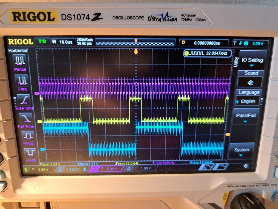
{
https://github.com/speccy88/TAQOZ/blob/master/src/forth/audio/WAV-I2S.FTH
https://forums.parallax.com/discussion/167868/taqoz-tachyon-forth-for-the-p2-boot-rom/p23

WAVE FILE PLAYBACK FOR PROPELLER 2 WITH ADAFRUIT MAX98357 I2S CLASS D MONO AMPLIFIER

CLOCK SETUP AT 80MHZ
16 KHZ SAMPLE RATE, 16 BITS RESOLUTION
BCLK FREQUENCY : 16KHZ * 16 (BITS) * 2 (LEFT/RIGHT) = 512KHZ

BCLK AND LRCLK GENERATED WITH 2 SMARTPINS IN NCO FREQUENCY MODE
WYPIN SET AT 2**32/2 = $8000_0000
WXPIN FOR BCLK : (80E6)/(512E3)/2 = 78.125 APPROXIMATED TO 78
200E6/512E3/2 = 195
WXPIN FOR LRCLK : 78*32 = 2496
195*32= 6240


DIN SETUP IN SYNCHRONOUS SERIAL MODE
IF YOU CHANGE DIN AND BCLK PINS, YOU NEED TO CHANGE DIN MODE CONFIG
DIN CLOCK PIN IS SETUP AT PIN + 2

LINKS :
https://learn.adafruit.com/adafruit-max98357-i2s-class-d-mono-amp/pinouts
https://cdn-learn.adafruit.com/downloads/pdf/adafruit-max98357-i2s-class-d-mono-amp.pdf
https://cdn-shop.adafruit.com/product-files/3006/MAX98357A-MAX98357B.pdf
http://soundfile.sapp.org/doc/WaveFormat/
}

--- ASSIGN PINS
14      := *LRCLK
12      := *BCLK
10      := *DIN

57 := dLedPin

--- SMARTPINS CONSTANTS
\ %AAAA_BBBB_FFF_MMMMMMMMMMMMM_TT_SSSSS_0
%1010 24 << ( B-input: x010 = relative +2 pin's read state 1= inverted )
\ %0010 24 << ( B-input: x010 = relative +2 pin's read state )
%1_11100_0 OR   := #SYNC_TX

%1_00110_0          := #NCO_FREQ
1 14 << NCO_FREQ OR     := #NegNCO_FREQ \ war 14
%001111             := #CONT-16BIT

\ : DISABLE_I2S         *LRCLK LOW *BCLK LOW *DIN LOW ;
: DISABLE_I2S           *LRCLK FLOAT *BCLK FLOAT *DIN FLOAT ;
: ENABLE_I2S            *LRCLK HIGH *BCLK HIGH *DIN HIGH ;


--- SMARTPINS SETUP
: !PINS
    DISABLE_I2S
    *LRCLK PIN #NCO_FREQ WRPIN ( 2496 )  6240  WXPIN $8000_0000 WYPIN
    *BCLK PIN #NCO_FREQ WRPIN ( 78 ) 195  WXPIN $8000_0000 WYPIN
    *DIN PIN #SYNC_TX WRPIN #CONT-16BIT WXPIN
    ;

\ Am Ausgang: MSB von Left kommt zuerst, (der syncTx mode schickt LSB first)
\ letzte 2 LSB bits werden noch übertragen, nachdem LRCLK gewechselt hat.
\ ausgegeben wird von der Platine default (L+R)/2

: seekDATA ( -- addr ) \ seek for the data header in WAV
   0
   begin
      1+
      dup sd@
   $61746164 = until \ "data" reverse
   \ sdPointer !
;

{
pre PLAY ( <filename> -- )
    [C] FOPEN
   key drop
--- WAVE DATA START AT ADDRESS 44, PRIME SYNC SERIAL SHIFTER
    44  DUP SDW@  REV 16>>
   ( addr data16 ) DUP 4* WYPIN
   ( addr data16 ) DUP 14 >> SWAP
   ( addr data2 data16 )
    ENABLE_I2S
   ( addr data2 data16 ) DUP ( addr data2 data16 data16 )
   -ROT 4* OR WYPIN 14 >>
   ( addr data ) SWAP 2+ WAITPIN
--- ADDRESS 40 IS SUBCHUNK2SIZE
    ( 40 )
      drop
      seekDATA dup 4 +
      SD@ 2/ 2 - ( subchunksize )
--- EXIT ON KEY PRESS OR EOF
    FOR
      i 12 >> dLedPin PIN!
      ( olddata addr ) DUP SDW@
      \ 15 sign 32768 +
     \ drop  $f  ( dup . )
     REV 16>> SWAP
     ( olddata data16 addr ) -ROT ( c b a -- a c b )
     ( addr oldddata data16 ) DUP
     ( addr oldddata data16 data16 ) -ROT
     ( addr data16 olddata data16 ) 4* OR
     *DIN PIN WYPIN WAITPIN
      ( addr data16 ) DUP 14 >>
     ( addr data16 data2 ) SWAP DUP
     ( addr data2 data16 data16 ) -ROT
     ( addr data16 data2 data16 ) 4* OR WYPIN 14 >> SWAP
     ( data2 addr ) 12 + WAITPIN
      KEY
    ?NEXT
   crlf @PIN .
   fclose
   DISABLE_I2S
    ;
}

: i2sOutLoop {: addr# samples# , data16# data2# -- }
   samples# for
      addr# SDW@
      \ drop $F \ test
      REV 16>> to_data16#
      *DIN PIN
      data2# data16# 4* or  WYPIN WAITPIN
      data16# 14 >> to_data2#
      data2# data16# 4* or WYPIN WAITPIN
      \ data16# 14 >> to_data2#  \ data2# is already there
      2 \ 2 for mario.wav
      +to_addr#
      key
   ?next
; forgetLocals


pre playI2s
   !PINS
    " mario.wav" FOPEN$
   key drop
--- WAVE DATA START AT ADDRESS 44, PRIME SYNC SERIAL SHIFTER
    44  DUP SDW@  REV 16>>
   ( addr data16 ) DUP 4* WYPIN
   ( addr data16 ) DUP 14 >> SWAP
   ( addr data2 data16 )
    ENABLE_I2S
   ( addr data2 data16 ) DUP ( addr data2 data16 data16 )
   -ROT 4* OR WYPIN 14 >>
   ( addr data ) SWAP 2+ WAITPIN
--- ADDRESS 40 IS SUBCHUNK2SIZE
    ( 40 )
      drop
      seekDATA dup 4 +
      SD@ 2/ 2 - ( subchunksize )
--- EXIT ON KEY PRESS OR EOF

   i2sOutLoop
   drop \ old data
   crlf @PIN .
   fclose
   DISABLE_I2S
;

\ playI2s
If I output $f I get the following picture, which seems to be OK. Yellow is data, blue is LRCLK. The signals change at high-low of the clock and the last 2 bits of LBS are still transferred after LRCLK changes. The timing of these phases is stable.
(It's the first time, that I play with I2S, so I am not completely sure.)
If I transfer real data, I can faintly hear some good signal burried in lots of noise.
Ah, it must be only one last bit send after LRCLK changes!!!!
Mario is playing now without noise.
{
https://github.com/speccy88/TAQOZ/blob/master/src/forth/audio/WAV-I2S.FTH
https://forums.parallax.com/discussion/167868/taqoz-tachyon-forth-for-the-p2-boot-rom/p23

WAVE FILE PLAYBACK FOR PROPELLER 2 WITH ADAFRUIT MAX98357 I2S CLASS D MONO AMPLIFIER

CLOCK SETUP AT 80MHZ
16 KHZ SAMPLE RATE, 16 BITS RESOLUTION
BCLK FREQUENCY : 16KHZ * 16 (BITS) * 2 (LEFT/RIGHT) = 512KHZ

BCLK AND LRCLK GENERATED WITH 2 SMARTPINS IN NCO FREQUENCY MODE
WYPIN SET AT 2**32/2 = $8000_0000
WXPIN FOR BCLK : (80E6)/(512E3)/2 = 78.125 APPROXIMATED TO 78
200E6/512E3/2 = 195
WXPIN FOR LRCLK : 78*32 = 2496
195*32= 6240


DIN SETUP IN SYNCHRONOUS SERIAL MODE
IF YOU CHANGE DIN AND BCLK PINS, YOU NEED TO CHANGE DIN MODE CONFIG
DIN CLOCK PIN IS SETUP AT PIN + 2

LINKS :
https://learn.adafruit.com/adafruit-max98357-i2s-class-d-mono-amp/pinouts
https://cdn-learn.adafruit.com/downloads/pdf/adafruit-max98357-i2s-class-d-mono-amp.pdf
https://cdn-shop.adafruit.com/product-files/3006/MAX98357A-MAX98357B.pdf
http://soundfile.sapp.org/doc/WaveFormat/
}

--- ASSIGN PINS
14      := *LRCLK
12      := *BCLK
10      := *DIN

57 := dLedPin

--- SMARTPINS CONSTANTS
\ %AAAA_BBBB_FFF_MMMMMMMMMMMMM_TT_SSSSS_0
%1010 24 << ( B-input: x010 = relative +2 pin's read state 1= inverted )
\ %0010 24 << ( B-input: x010 = relative +2 pin's read state )
%1_11100_0 OR   := #SYNC_TX

%1_00110_0          := #NCO_FREQ
1 14 << NCO_FREQ OR     := #NegNCO_FREQ \ war 14
%001111             := #CONT-16BIT

\ : DISABLE_I2S         *LRCLK LOW *BCLK LOW *DIN LOW ;
: DISABLE_I2S           *LRCLK FLOAT *BCLK FLOAT *DIN FLOAT ;
: ENABLE_I2S            *LRCLK HIGH *BCLK HIGH *DIN HIGH ;


--- SMARTPINS SETUP
: !PINS
    DISABLE_I2S
    *LRCLK PIN #NCO_FREQ WRPIN ( 2496 )  6240  WXPIN $8000_0000 WYPIN
    *BCLK PIN #NCO_FREQ WRPIN ( 78 ) 195  WXPIN $8000_0000 WYPIN
    *DIN PIN #SYNC_TX WRPIN #CONT-16BIT WXPIN
    ;

\ Am Ausgang: MSB von Left kommt zuerst, (der syncTx mode schickt LSB first)
\ letztes LSB bit wird noch übertragen, nachdem LRCLK gewechselt hat.
\ ausgegeben wird von der Platine default (L+R)/2

: seekDATA ( -- addr ) \ seek for the data header in WAV
   0
   begin
      1+
      dup sd@
   $61746164 = until \ "data" reverse
   \ sdPointer !
;

: i2sOutLoop {: addr# samples# , data16# data2# -- }
   samples# for
      addr# SDW@
      \ drop $F \ test
      REV 16>> to_data16#
      *DIN PIN
      data2# data16# 2* or  WYPIN WAITPIN
      data16# 15 >> to_data2#
      data2# data16# 2* or WYPIN WAITPIN
      \ data16# 14 >> to_data2#  \ data2# is already there
      2 \ 2 for mario.wav
      +to_addr#
      key
   ?next
; forgetLocals

pre playI2s
   !PINS
    " mario.wav" FOPEN$
   key drop
--- WAVE DATA START AT ADDRESS 44, PRIME SYNC SERIAL SHIFTER
    44  DUP SDW@  REV 16>>
   ( addr data16 ) DUP 2* WYPIN
   ( addr data16 ) DUP 15 >> SWAP
   ( addr data2 data16 )
    ENABLE_I2S
   ( addr data2 data16 ) DUP ( addr data2 data16 data16 )
   -ROT 2* OR WYPIN 15 >>
   ( addr data ) SWAP 2+ WAITPIN
--- ADDRESS 40 IS SUBCHUNK2SIZE
    ( 40 )
      drop
      seekDATA dup 4 +
      SD@ 2/ 2 - ( subchunksize )
--- EXIT ON KEY PRESS OR EOF

   i2sOutLoop
   \ i2sOutSin
   drop \ old data
   crlf @PIN .
   fclose
   DISABLE_I2S
;

\ playI2s
Still wondering, if there was a change in the behaviour of M6 which might perhaps explain, that this old code does no more work.
Looking at those scope traces, inverting BCLK will phase shift it with respect to the LRCLK. That might screw with which data bit gets clocked first into each I2S channel.
EDIT: Doing a little reading, I'm surprised to find the data is meant to lag behind the LRCLK by one BCLK. It's different to what I remember from a couple a decades ago. I was reading AC97 specs that had it as LSbit first, but the modern chips seem to be MSbit first now. Same as SPI.
So that means the data trace above is one BCLK late. Inverting BCLK could shift the data later still.
Ah, it's simple a typo! #NCO_FREQ and NCO_FREQ !