

Key Fob Remote (#700-10016) wire connection

Hi application engineers and hobbyists,
I am going to use a Key Fob Remote (#700-10016) to control a stepper motor, two keys for forward and backward movement controls, other two keys for speed-up/down controls.
The Key Fob receiver guide has a description, table, and drawing as shown below, I am confused with the use of VT. The description gives an option to select VT or D, however, both the table and the drawing show that VT should be used together with D. The remote has only 4 keys, D1 through D4 should work for the 4 keys, why is VT pin there connecting other D pins?
Description
Table
Drawing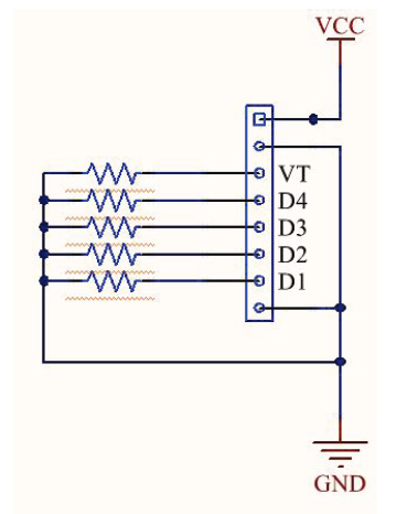
The attached file is the guide.
I have a wire connection drawing included below for my project, I left VT unconnected. Three 9 V rechargeable batteries (8.2-8.4 V at full charge) are used to power a stepper motor that is rated for 24V use. A resistor divider is used to split the voltage to power the wireless receiver, providing 5.66-3.45 V to the receiver for the battery voltage range of 24.9 - 15 V. The motor controller has only 3 digital pins, I have to use an analog pin as a digital pin for my project.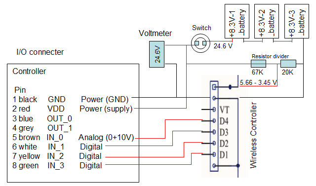
Could I trouble you to check if the wire connections are OK?
Thanks,
Gu
Comments
Hi !
Not sure about the circuit, but about VT and D.... from what I remember the signal from VT operates for any button press, whereas D1 to D4 operate only for the specific button press. I think you could use either or both in your project. If you have a multimeter available you should measure the pins to confirm.
Edit: Looking at the circuit of the VT and D pins, it shows pull-down resistors are recommended for each signal output. Probably you'd need to add those in your circuit. 10K should be fine. That would suggest the outputs are open-collector, so after adding the resistors you will measure high when a button is pressed, and it will be pulled low when the button is not pressed. Something like that !
Hi VonSzarvas,
Thank you for your prompt reply.
It is hard to understand that VT operates for any button press, it would be nice to have that function for an emergency stop by pressing any bottom. My motor controller has no pin for VT. The motor controller has a 32K resistor between the digital pins and the GND for circuit protection, so additional resistors are not necessary.
Regards,
Gu
I've used these before on one of my projects. I have D1,D2,D3,D4 going into the propeller 1 Pins with a 10k resistor in series. The VT I had it going to an LED, to indicate when any button was pressed. Or you can run to a pin with a 10K.
Hi DigitalBob,
Thank you for your reply.
I run into a very strange situation. I used 67K and 20 K resistors as a voltage divider as shown in my original post. it supposed to convert 24V (three 9V batteries) to a 5V to power the wireless receiver, however, it just produced 1.3 V.
Then, I used a 5V battery (5.08 v) to directly power the receiver, it produced a 1.95 V, see the attached photo, The led light did not turn on, meaning 1.95 V was not able to drive the receiver.
The battery's voltage kept at 1.95 immediately after disconnect the receiver from the battery, and the battery's voltage resumed to 5 V gradually within 20 minutes
I tried three receivers, all of them had the same behavior. I do not understand why the receiver reduced battery's voltage.
Do you have any thought?
Best regards,
Gu
Is that 9V battery directly connected to the multimeter? If you can only measure 5V whilst unloaded (whilst the battery is not powering the circuit) then that 9V battery is essentially finished. You'll need a new battery.
Other than that, it seems like you are thinking about the voltage, but not the current needed to power the receiver. So at zero load you could measure 5V, but when 100mA load (or whatever that receiver requires) is added to the circuit, then things will change. Consider V=IR.
I would suggest you consider a simple experiment:
Once you know the current needed for your device, then consider that in your calculations for your resistor divider. I'm not certain your voltage divider resistor values shown above will allow enough current to pass through to power the receiver without significantly dropping the voltage lower than you are expecting. And that seems to be what you are finding with your multimeter measurements.
This simulation might help show what happens as the load is connected/disconnected, and as the load current varies with the slider on the right: https://tinyurl.com/2kpxn4jf
In that simulation, see what happens as you experiment with the resistor divider values (right click/edit on any component value to change it). Also, hover over the resistors to see the power dissipation is not more than the power rating (Watts rating) of your resistors.
Finally- you might also consider some sort of voltage regulator to replace the voltage divider, although I'm assuming you didn't want to do that- and in which case it's good to experiment some more to figure out what is possible by measuring the current needs of your circuit, and understanding the impact that will have on your voltage divider resistor values.
Use a 5 Volt regulator such as a LM78L05. Just have a switch from your battery to the regulator, so you can turn it off when not is use, to conserve the battery life.
Hi VonSzarvas,
Thank you for your time writing in details.
Yes, the 9V was directly connected to the meter, but it was a used 9V, having 5 V left. I thought it might be good to power the receiver that just needs 5V.
The voltage divider was tested with 3 fully charged 9V batteries, measured 24.5V total. The divider produced a 1.3V, strange!
I will try three 1.5V batteries as you suggested and will let you know the result.
Gu
I found this quote that covers battery expectations well...:
You might be able to measure some voltage across the battery terminals, but the battery simply has no "oomph" to deliver the charge into an actual load (circuit), and so the voltage will collapse once you connect any sort of load to it. (Which is exactly what your experiment showed).
Hi VonSzarvas,
I did some tests on the wireless controller, below is a simplified circuit and test results.
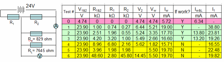
First, I used three AA batteries with total voltage 4.74V to power the wireless receiver, it worked fine, the voltage maintained at 4.74V after connection of the receiver, the current draw was 5.72 mA at no load and 6.34 mA at remote button press, meaning the current draw from the batteries increased 0.62 mA. The result is listed as test #0.
Then, I used some resistors available at my hands and did some tests on voltage divider using different combinations as listed in the table. The circuit used a resister value of Rw = 829 ohms for the wireless receiver, which was calculated using Rw = 4.74/0.00572 = 829. A resistor of RL = 7645 ohms for the remote control load, which was calculated using RL = 4.74/0.00062 = 7645. R2, Rw and RL are considered as parallel, V2 and Vw were measure without and with the wireless receiver connection respectively. Iw and Iw&L were measured when the receiver was connected and the remote button was pressed down, respectively. I1 is the current for R1 and also the total current.
It can be seen that there was always a voltage drop from V2 to Vw when the wireless receiver was connected, and a current drop from Iw to Iw&L when a remote button was pressed down as shown in test #2 & #3. While, this is significantly different from the 3-AA battery powered case. The 4.74V was kept unchanged when the receiver was connected and the current had an increase at the remote button press. For the 3-AA battery powered case, the current increase is consistent with the parallel circuit due to the overall resistance value decrease. For the case of the three 9V battery and a voltage divider, the current decrease seemed abnormal.
In the case of using a voltage divider, it is not hard to understand the reason for the voltage drop after digesting the test results, however, it is difficulty to understand why the current, Iw, was about 3 times (16-19 mA) of the 3-AA battery powered case ( 5.72 mA), the total current draw from 24V battery, I2, was in a range of 20-40 mA, which is a big concern on battery service duration.
Test #6 is a desired extreme case, where a R2=45.8k resistor was used to divert current from R1 to Rw and RL, minimizing current flow to R2, it created 5.5V for the receiver, theoretically, the current draw, Iw, supposed to be less than 7mA. However, the wireless receiver did not work even though the current draw was measured 19.7 mA.
I am going to try a voltage regulator, https://www.digikey.ca/en/products/detail/texas-instruments/LP2950-50LPRE3/1216539, its working temperature can cover winter use. but, the datasheet shows that it seems having an internal voltage divider, I do not know if it will have a similar effect to draw more current from input source.
Could you please provide some inputs?