

Waveshare touchscreens at 1024x600 and P2 HDMI/VGA
 rogloh
Posts: 6,414
rogloh
Posts: 6,414
Following on from some discussions in the USB development thread, we have found that these reasonably inexpensive 7 inch Waveshare LCD capacitive touchscreens can be driven via HDMI and will also report touch positions via USB which can be read by the P2.
https://www.waveshare.com/7inch-hdmi-lcd-h-with-case.htm
@pik33 came up with some sample timing for his HDMI driver which appeared to work when I tested a binary he supplied, although much of the screen was blank apart from a mouse sprite so I couldn't really check all pixels.
'                      bf.hs,hs,  bf.vis  visible,up p., vsync, down p.,  cpl, total lines, clock,       hubset                                scanlines  ud bord mode reserved
timings         long   8,    60,  8,      1024,   4,     4,     4,        128, 600,         336956522,   %1_101101__11_0000_0110__1111_1011,   600,        0,     192, 0, 0
I also tried this out in my own driver with some text and found it can be coaxed to give pixel perfect output at ~50Hz refresh with a 1024x600 resolution which is quite good for the P2 over HDMI/DVI.
You will need to clock the P2 rather fast for this, ~337 MHz.
I used these custom timing values in the end although I know it can be varied a bit more and still work. It seemed to need 7 lines after sync to get the first row of pixels at the top of screen.
text.initDviCustom(-1, 0, 0, 0, 337000000, 10, 1, 8, 60, 8, 128, 1, 4, 4, 7, 600)
- hfront=8
- hsync=60
- hback=8
- active pixels=128*8=1024
- total pixels=1100
- vfront=4
- vsync=4
- vback=7
- active lines=600
- total lines=615
- positive H&V sync, not sure it matters a lot.
Here's a close up of some of the LCD pixels with some fine text, no scaling is happening so it's showing as 1:1 over HDMI which is great. I made a diagonal line character and some staircase steps per scanline to prove they are exact pixels.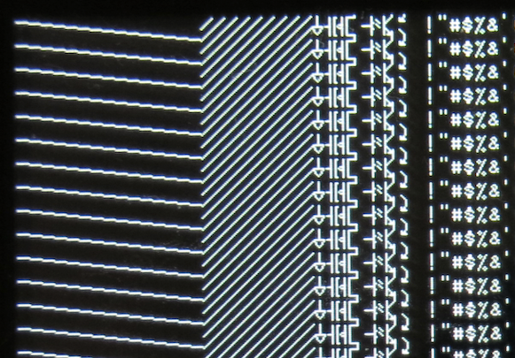
Unfortunately to date I've not been quite as successful with the VGA input for this screen. It seems to be getting scaled even when I natively send it 1024 pixels per row - although I can get the scan lines themselves to not scale vertically. There is an OSD which can vary the sample clock and phase for VGA input but I can't make it line up perfectly with 1024x600 pixels no matter how hard I tried so far. But sending it 800x600 actually gives very good results, its scaling appears optimized for that resolution in particular and it looks pretty decent.
I found this Waveshare LCD data sheet and used the exact timing it provided but it didn't help. Might be the input chip before the LCD doing it's own resampling on the VGA input, or this data sheet was not for the LCD inside the touchscreen model I have (LCD Model H with case).
https://www.waveshare.com/w/upload/1/1a/7inch_1024X600_LCD_DS.pdf
But the good news is this touchscreen should work nicely with the P2 with HDMI and ultimately could support touch via USB with some suitable report format decoding tweaks added there.
Comments
Aha, tried signalling over the VGA input using 1024x768 timing and am getting much better horizontal pixel alignment on this screen but vertical is off and is being scaled with lots of blank lines at the bottom of the screen. I think the other stuff I was trying to date was getting the LCD to scale to 1024 only assuming 800 pixels were being sent. If I can send 1024x600 with extra blanking it might fix it....
EDIT: NOPE.
If they use "standard" VGA input chip, it maybe "doesn't know" what is 1024x600 (this is non-standard for VGA) - it only knows 800x600 and 1024x768. HDMI works") This extra 3 (7 instead of 4) lines makes the frequency slightly less than 50 Hz - maybe this can be compensated elsewhere, either on H or V.
This extra 3 (7 instead of 4) lines makes the frequency slightly less than 50 Hz - maybe this can be compensated elsewhere, either on H or V.
VGA to LCD scan converters inside monitors and TVs are all different. No two are the same. And they all lie about their capabilities in their EDID dumps too.
Yeah I'm beginning to lose hope that VGA will achieve 1:1. It seems to either scale assuming 800x600 or 1024x768. No problem, we can use HDMI, you just need a fast P2. 24bpp colour should be doable from a PSRAM framebuffer at this P2 clock speed too.
The input chip is that RTD6660 device I believe based on the rear board image in this page - my case PCB variant is a slightly different board but IIRC has the same chip.
https://www.waveshare.com/7inch-hdmi-lcd-h.htm
As far as those 3 lines, yeah I found it still works with as few as 10 total vblank lines, and 1,2,7 or 2,1,7 both worked. You can increase vfront more too. An exact 50Hz could be achieved with a pixel clock of 50 * 610 * 1100 ie. P2 running at 335.5MHz. Or if you need it to be something else, tweak the blanking more.
Yeah. What kinda annoys me is that this scaler does a damn good job with inputting 800x600 but doesn't want to let me send in 1024x600 without ruining it.
I was originally hoping I could fit a P2Edge inside this LCD case and wire up to the VGA pins internally with fine wires soldered to the gold edge connector. There's almost enough room to hold it, but would probably need to Dremel out a bit more from the back plastic I think, it's tight.
You could power the P2 board from the 5V micro USB input and also tap into the USB pins, maybe fit a USB-serial breakout board on the power only USB pins if they can be soldered too, so you could program the internal P2 Edge. If the VGA had worked I could then also feed more wires out to the original connector for external VGA output (on more P2 pins). The HDMI port could be retained for external input use from other devices. This LCD overrides a VGA signal when HDMI is present as I recall.
Update:
Here's a pic of the innards of this thing.
I found a couple of good looking web pages:
https://tomverbeure.github.io/video_timings_calculator provides CVT timings and https://www.improwis.com/tables/video.webt provides the following list:
pixel front back front back Htotal Vtotal hsync vsync clock porch hsync porch porch vsync porch mode name res pixels lines kHz pol pol MHz pix pix pix lines lines lines === WSVGA 1024x600 128:75 // between 15:9 and 16:9; 7-10" screens; ultramobile PCs, netbooks, tablets; full 1024pix XGA width; common Android devices; Kindle Fire, Nook Color d 7" Waveshare HDMI 1024x600@43.066 1152 645 27.7778 - - 32.000 40 48 40 13 3 29 from EDID; [ref] a arcade monitor 1024x600i@25.0 1264 638 16.0 - - 20.161 8 95 137 1 6 31 arcade/game modelines; fixed hsync freq arcade monitor a SailorSat 15kHz i 1024x600i@25.1 1328 627 15.7380 - - 20.900 48 104 152 7 3 17 soft-15kHz, SailorSat's arcade emulator modes [ref] a SailorSat 31kHz p 1024x600@50.201 1328 627 31.4759 - - 41.800 48 104 152 7 3 17 soft-15kHz, SailorSat's arcade emulator modes [ref] e RGB BM800480 1024x600@56.37 1313 635 - - 47.0000 119 10 160 9 3 23 den_pol=0, dclk_pol=0, LVDS_8BIT_1, OUT_P888; for BYD 5' LCD BM800480-8545FTGE; [ref] e LVDS HH070D 1024x600@57.98 1344 770 - - 60.0000 120 100 100 150 10 10 den_pol=0, dclk_pol=1, LVDS_8BIT_2; [ref] e RGB B101AW06 1024x600@58.10 1214 638 - - 45.0000 100 10 80 18 10 10 den_pol=0, dclk_pol=0, LVDS_8BIT_1, OUT_D888_P666; [ref] e RGB HV070WSA 1024x600@58.59 1344 635 - - 50.0000 120 100 100 15 10 10 den_pol=0, dclk_pol=0, LVDS_8BIT_2, OUT_P888; [ref] d LS-7T display module 1024x600@59.852 1312 624 37.3476 - + 49.000 48 96 144 3 10 11 HDMI/DVI/VGA 7" touchscreen display, buggy EDID [ref] c VGA VIA 1024x600@60.00 1312 622 37.252 - - 48.875 40 104 144 1 3 18 fb.modes, VIA; commented out c GTF 1024x600@59.995 1312 622 37.3171 - + 48.960 40 104 144 1 3 18 common X11 modelines c VGA VIA 1024x600@60.00 1312 622 37.320 - - 48.964 40 104 144 1 3 18 fb.modes, VIA d 7" HDMI MPI7002, pri 1024x600@60.04 1312 622 - + 49.000 5 13 270 2 3 17 from EDID, hands-on hardware, native mode, mode #0; flags: nhsync, pvsync; type: preferred, userdef, driver e RGB E242868 1024x600@60.85 1274 645 - - 50.0000 210 30 10 22 13 10 den_pol=0, dclk_pol=0, LVDS_8BIT_1, OUT_P888; [ref] e LVDS/RGB SK616 1024x600@66.79 1344 635 - - 57.0000 160 20 140 12 3 20 den_pol=0, dclk_pol=1(LVDS)/0(RGB), LVDS_8BIT_1, OUT_P888; [ref] e RGB AT070TNA2 1024x600@68.22 1344 638 - - 58.5000 210 10 100 18 10 10 den_pol=0, dclk_pol=0, LVDS_8BIT_1, OUT_D888_P666; [ref] e LVDS SKLVDS1024x600 1024x600@70.46 1152 616 - - 50.0000 18 10 100 6 2 8 den_pol=0, dclk_pol=0, LVDS_8BIT_1, OUT_P888; [ref] e LVDS/RGB SK616 1024x600@70.95 1293 654 - - 60.0000 119 10 140 30 6 18 den_pol=0, dclk_pol=1(LVDS)/0(RGB), LVDS_8BIT_1, OUT_P888, has dsp_lut; [ref] e LVDS/RGB HDMI 1024x600@76.57 1234 635 - - 60.0000 160 10 40 12 3 20 den_pol=0, dclk_pol=0, LVDS_8BIT_1, OUT_P888; [ref]Thanks @evanh will try some of these later. I did just try that 43Hz mode that mentioned 7" Waveshare which I hadn't seen before but it didn't work. Screen just repeatedly flashes like it's resetting or something.
Yeah, the HDMI modes will be too small h-blanking. Also, aim for modes with h-sync greater than 30 kHz. There was sort some sort of ban on analogue modes (except for 15 kHz TV modes) lower than 30 kHz.
SUCCESS!! One of these modes finally worked over VGA and the pixels are clean. Thanks again @evanh!
Cool! I wasn't holding my breath but I'd had the same sort of success with other resolutions too. And as Pik implied, VGA inputs are often quite fussy about timings.
It is already done at 1024x576 so it should work after adjusting timings to 1024x600. This thing has also 16 hub based sprites.
For sure, there is enough bandwidth for this. 4kB read per 1024 pixel scan line at a line frequency of ~37kHz is about 150MB/s read bandwidth or thereabouts (slightly more if you include other overheads). A >300MHz P2 with 16 bit PSRAM is plenty for sustaining that with lots of spare bandwidth left for graphics writes and the overheads. Nice.
Having the VGA fully working now too is great also in that you can get by without the 10x pixel clock requirement of HDMI if you want to clock the P2 slower for any reason (or for 60Hz refresh instead of 50Hz).
I used a 4-line hub buffer and a pipeline there. The driver displays line on the screen from a HUBRAM buffer using the streamer, renders sprites for line+1 using the driver's cog and loads the line+2 from the PSRAM using the PSRAM cog.
Will have to see if I can get Chip's tiny font stuff working on this thing. With a simple 8x8 DOS font I was able to get 128x75 resolution text over VGA. Photo is not great as it's low light here now, looks much better in real life.
Wow, great progress today. Looks impressive
Can you try the 7" with
My 5" version works with this.
1024x600 on a 5" = a microscope is needed to read this, even 8x16 I use. However this 5" is 800x480, downscaling 1024x600
Hmm, intriguing, I think GTF is depreciated these days, but I guess many older converter chips probably use it. In particular ones with VGA inputs.
Looking up the doc - https://glenwing.github.io/docs/VESA-GTF-1.1.pdf - it says default vsync pulse length is 3 lines. Even though that's not a hard number, I do wonder if maybe that's used by these chips as a factor in gauging what mode they choose. Another one is hsync+BP must be defaults to 8% of htotal. Which is a much more rigid number. EDIT: Err, not fixed at 8%. Nothing is solidly fixed but defaults will rule the roost I suspect.
I hadn't tried to use GTF in the past myself. I kept using the more modern CVT and even newer ones for digital interfaces.
Well my fun may be short lived....as I can't get it to power back on and display anything now. I had left this LCD sitting on standby (I think I'd pressed its soft power off button) during dinner and the P2EVAL board was also unplugged from the Mac. I wonder if some spike hit it from its own USB power supply - it's a potentially dodgy wall wart powerstrip USB-A capable of 4.5A output! which I've not used before for any long durations before today.... will have to open this LCD up tomorrow when I'm more alert to see if something got fried near its regulators or what else might be causing this. Ugh.
Oops...
Meanwhile I found a repository with different sized bitmap fonts.
https://github.com/idispatch/raster-fonts
It's working again. Tried to power up this LCD panel again today and it started working with VGA output. I wonder if there was a polyfuse that had a problem? I'm going to use a "better" 5V supply (Raspi USB) for now.
Update: Far out, my multimeter is reading 85VAC between this power strip's USB gnd and my oscilloscope's ground plugged into the same power strip. Doesn't seem fully/well isolated. What a POS. In comparison Raspi power supply USB gnd measured 4VAC to same scope ground. I still prefer the iron core transformers of old, they just seem more trustworthy.
Yes that vertical blanking timing worked. Tried it with these settings below.
text.initDviCustom(-1, 0, 0, 0, 337000000, 10, 1, 8, 60, 8, 128, 1, 1, 4, 7, 600)Ah, yes, the joys of "double insulated" equipment. It's more a side effect of internationalised appliances. Phase and Neutral are treated as the same - both are considered as live. Not a problem of itself but without an Earth pin there is no way to stop the appliance from floating to 50% of AC volts or thereabouts.
Leakage is minimal, although it can be enough to tickle when touched.
PS: Plugging into USB with AC already present is the sort of thing that can trip out an entire tree of buses.
Or kick hard. Some manufacturers think, the higher capacity, the better. It was long time ago when I was electrocuted by the frequency counter that had something like 110V AC ot its case. The ground wire in the wall plug was broken and these big capacitors did the rest.
Oh, that's way different - Not a double insulated appliance - You've got a faulty appliance circuit there. The Y-class filter caps will drag the frame volts much stronger to 50% of line volts, yes.
I remember getting a small shock from some HDMI lead from some splitter gear I had that was powered by one of these cheapo power bricks that wasn't well isolated. That thing died shortly afterwards too. No wonder really.
Not too surprisingly, medical equipment has more stringent requirements on leakage.