

P1 to P2 Migration
 pilot0315
Posts: 1,014
pilot0315
Posts: 1,014
I was very adept at P1 in Spin and Pro C.
Since many of you are "professionals" in coding at a very high level. It was easy for you to over the years of the inception of the P2 to create wonderful code. Now this leaves the others who are novices so to speak to jump right in or migrate over. The P2 is so powerful that it can be overwhelming. Kudos to @cgracey.
Now I would like to start a thread where we can take simple code from the P1 and migrate to the P2.
@JonnyMac wrote a thread that started a P1 to P2
https://forums.parallax.com/discussion/172389/moving-from-spin1-to-spin2#latest
I followed the code instrctions but the code did not work. Not his fault. I will post later.
I think that it would be benificial to all if we can and as I will attemp to do, follow the PE kit documentation and move forward with a manual for the newbies.
I will be using the from the beginning code and moving forward, one the issues is the counters from the P1. I know that the P2 does not have cogs that we can program. Alas as we say in French, tampi pour nous, they were easy to use.
I will move slowley though the code and will need some assistance.
I would like to stay in SPIN to start then move to P2asm slowly to really teach the two. I was able to get through the basics of P1asm as assembly language is really not taught in the colleges any more.
We are on our own.
So I wish that we can start with the first chapter that I will post shortly with my P1 code and the direct translation of P2 code and ad later the P2 pins in a manner that we can all underatand.
Comments are pleased welcome.
Comments
BTW
I would like to re write the PE manual with your help.
Thanks
Suggestion: One-by-one, put up examples from the PE book and ask others to contribute their P2 version. You will get different approaches that will be successful. From those, you can synthesize what you think is best and then document that code for beginners.
Personally, I have found moving to the P2 very easy, with the exception of losing the cog timers; I have many P1 projects that use simple timers and those take a little more effort to deal with in the P2. If you thought P1 PASM was easy, boy are you going to love P2 PASM. Yes, a lot more instructions, but many of them replace two or more instructions that were needed in the P1. And with inline PASM in the P2, it's really easy to learn by testing little snippets of code -- no additional cog required.
Basics of P1 --> P2
I wrote a Python program that will scan a P1 listing and give me suggestions on things to fix and a hint on how to do it. I have posted that in the forums. Some of the work is grunt work. I tend to use Propeller Tool so I press F9 to compile fix and error and move on. If using Spin Tools (from @macca) it does a constant compile process so you can click on the yellow and red tags to fix as you go. In the end, there's no magic bullet, you just have to slog through. You also have to prepare for going back later and realizing that you've learned something new about the P2 that will make your code better. Always be willing to update your code.
Okay, I'll start. This is how I would translate the first program which changes the flashing rate of LEDs based on the state of a button.
I'm a a bit of a stickler for clean, professional programming style -- even for simple test programs like this. The problem I have with the author's approach in the PE Kit is -- in his words -- much of it is quick and dirty. My contention is that it's never quick, and it's nothing but dirty. The PE Kit teaches bad habits that can cause problems, especially as programs grow more complex.
My rules
The good news is that Spin2 seems stable now. Been hard to deal with code that is constantly changing…
I was working with the outa.[ ], the pin toggle and other combinations.
Noted that using pintoggle(0..1) toggles all of the lower 32 pins.
Tried pinhigh and pinlow got the same.
dira and outa with the period and only get the second pin.
Ref: Page 56 in the PE manual and page 10 of the Spin two documentation.
What is the correct syntax.
Thank you in advance.
Martin
It's easy to mess up with pinfield and bitfields in Spin2.
your problem might be having the lower number first.
Think needs to be pintoggle(1..0)
Attempting a direct/rote translation of P1 to P2 code is 1) not going to work in many cases, and 2) fails to take advantage of P2 features. We are forced to use outa[] and dira[] in the P1 because there are no high-level IO commands in Spin1. This is not true of Spin2, which also has two sets of IO registers to deal with (a group and b group) which can make things confusing unless the high-level commands are employed. The P2 outa[] and outb[] registers don't allow ranges like in Spin1 (this may be something for Chip to flag as an error). The only way I was able to get that syntax to work is like this:
This writes to the pins but clears everything else (no isolation of LED group without more code). Why do this to a newbie when the P2 has nice, pin-centric IO functions?
This is how I would merge those to programs while keeping with my persnickety rules about writing clean code from the jump.
con { app io pins }

  LED06    = 09  { O }
  LED05    = 08  { O }
  LED04    = 07  { O }
  LED03    = 06  { O }
  LED02    = 05  { O }
  LED01    = 04  { O }

  LEDS     = LED01 addpins 5                                    ' use LED01..LED06


pub main()

  repeat
    blink_v1()
    blink_v2()


pub blink_v1()

  pinwrite(LEDS, %100001)
  waitms(250)
  pinwrite(LEDS, %011110)
  waitms(250)


pub blink_v2()

  repeat 2
    pintoggle(LEDS)
    waitms(250)
Bear in mind, there are a few areas where the P1 has advantages (like the ranges in [] brackets), but overall, Spin2 is cleaner. Reverse engineering is not about copying, it's about applying intent in a new system.
Notes:
outa[x..y] :=in a P1 program, replace it withpinwrite(x addpins z)in the P2!outa[x..y]in a P1 program, replace it withpintoggle(x addpins z)in the P2z = MSBpin - LSBpin - 1. Again, the P1 has a bit of an advantage here because P2 pin groups are always from the LSB upward. To reverse output bits in the P1 we can do this:
To reverse the bit order in the P2 we would have to do this:
pingroup = LSB addpins (MSB - LSB - 1)
width := MSB - LSB + 1
I had a coffee break and found this is as close to rote as I could get the program -- but this is STUPIDLY UNFRIELDLY (as is the original P1 code). Note that in the P2 syntax you must use dot notation for the bit group, and the order of the bit group must be MSB..LSB (as Ray suggested).
pub main()

  dira.[9..4]~~

  repeat
    outa.[9..4] := %100001
    waitct(clkfreq/4 + getct())
    outa.[9..4] := %011110
    waitct(clkfreq/4 + getct())
In the P2, using the ! (bang) syntax works like this:
pub main()

  dira.[9..4]~~
  outa.[9..4] := %100001

  repeat
    != outa.[9..4]
    waitct(clkfreq/4 + getct())
These programs work, but make the P2 and Spin2 look scary -- and that's not necessary given the Spin2 pinxxx() and waitxx() functions.
The other interesting mistake is in Jon's thread: https://forums.parallax.com/discussion/172389/moving-from-spin1-to-spin2
Where @Ariba pointed out that outb.[56] does not do what you might expect.
That was a good catch by Andy -- as he so often does. It also demonstrates another reason not to use IO registers in Spin2 when simple IO commands are available. Pin groups and bit groups can be tricky.
Note that thread is from the early days of Spin2 (but still a mistake on my part).
So I have questions about your code:
What does the P_LOW_15K do and why did you choose it over the other P_LOW_xxx modes listed in the Spin2 docs?
Am I correct that these lines of code replace the "DIRA[PUSH_BTN] := 0" of Spin1?
Also, am I correct in assuming that the "PRESSED" in the following equals 1 or TRUE?
if (pinread(PUSH_BTN) == PRESSED) ' if pressed
I noticed that you encased the pinread command in parentheses. So what would be the correct way to do multiple pin tests?
if (pinread(PUSH_BTN1) == PRESSED) AND (pinread(PUSH_BTN2) == NOT_PRESSED)
or
if (pinread(PUSH_BTN1) == PRESSED AND pinread(PUSH_BTN2) == NOT_PRESSED)
Last question, I thought the P2 ran at a maximum of 180MHz according to the hardware spec sheet, but I see your push button code over clocks that to 200MHz and I have seen code that clocks it even faster. What is the best clock speed? The Spin2 doc has a program that clocks it at 297MHz right there on page 3.
The P2 is interesting in that you select how to drive an output.
This line inserts a 15K resistor between ground and the pin output. Why 15K? If you look at digital designs you'll see pull-ups generally in the range of 10K to 50K, sometimes higher. 10K is nearly a standard, and 15K is available to us. The pin is held low but is not too sensitive to noise. There is a case where I choose the150K pulldown: when using an IR sensor. The IR sensor has a 20K pull-up inside so the input would see ~2.9v on the input when the IR sensor is connected, but not active. If the input goes low and stays low, I know the sensor has been disconnected.
This line sets the DIRx bit to 1 (output) and the OUTx bit (level) to 0. The pin will be low now because of the 15K resistor inserted and we're connecting the up-side of the resistor to ground (LOW). This is just like hanging a resistor between the pin and ground, except that we can change its value and completely disable it.
There are many ways to skin that cat, but I would tend to do this
It would probably work without the outer (), but for my eye I like to use them to identify the entire expression. When in doubt I start with a shell like this:
...then I start filling the expression parenthesis.
The max speed is well above 180MHz -- many are running 270 (seems to be good for video) and even higher. I settled on 200 because it's near the "norm" and a nice, round, number (easy math). Some have suggested the P2 gets thermally sensitive above 320MHz. I've run a few quick tests at 300MHz, but that's not my standard.
Here's my question: Are you just looking at code, or are you actually experimenting? The latter is the best way to learn. Give yourself a bit of time each day and it will soon make sense.
To answer your question, I purchased a "P2 Eval board" and the "Eval Accessory Set". I also tested switches that were wired for Active_Low which is what I use in my project.
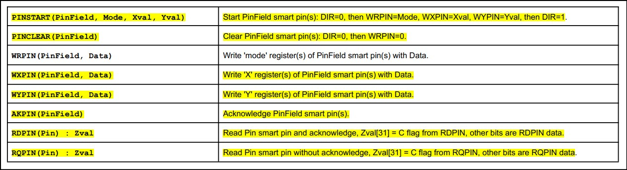
What does the PINFLOAT method do and when would you use it?
What is the definition of a PinField?
So if you set it P_HIGH_15K, do you still hardwire a pullup resister like below or is that done internally by that command?
You do know that there is online documentation for the P2, right?
-- https://docs.google.com/document/d/16qVkmA6Co5fUNKJHF6pBfGfDupuRwDtf-wyieh_fbqw/edit
In future, go to this web page, press Ctrl+F, and enter a search term.
The pinfloat function does what it suggests: it disables the output drive on the specified pin(s).
A PinField is a value that holds the base pin and number of additional pins in a contiguous group. You can use addpins to create a PinField constant or variable.
The first number is the base pin (LSB) of the group. The second number is the additional pins in the group. This particular group will include pins 0..7. This is how the P2 writes or reads multiple pins.
That's the point -- for most cases (not all), you don't need external pull-ups or pull-downs. To see internal pull-ups as in the example diagram.
Yes, we are making the pins outputs, but they're being driven through 15K resistors. The input registers work no matter the output state of the pin.
Your turn. Start exploring the docs and experimenting with your Eval board.
I'm sorry. I thought this was a place where no question was a dumb question.
I have downloaded the Spin2 document and I am trying to understand the listings in the PIN METHODS. I have downloaded the entire OBEX and I have been searching both it and the forums for each pin method. I played for a week trying to figure out why the PINREAD command would not read the pin until you showed me that I have to put the pin into a mode with the above WRPIN and PINLOW commands.
What the Spin2 manual is lacking is the command by command syntax and explanations of the listed functions like the Spin1 manual had.
Strait from the Spin2 link that you sent me.
Seriously what is all this mean? I probably need to wait longer until Parallax writes a more comprehensive manual on Spin2
You have explained the WRPIN command now and I can play with that. I think that with the pin commands on the page 10 and the WRPIN command on page 11, I may have what I need to convert my project. You already wrote an object for the RTC that I have on my boards.
Thank you for your help
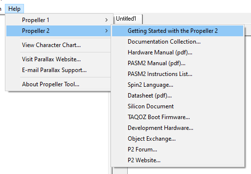
Of course anyone can ask anything in these forums; my suggestion is that you don't have to wait for an answer given the information the rest of us learned from -- albeit fragmented -- is available. If you're using Propeller Tool, the Help menu has access to a lot of information
I have these links bookmarked -- these are the original documents that most of us have learned from
On the Parallax website
Unfortunately, no Spin2 manual yet, so we have to relay on the docs above.
Forum user, Ada, created this hyper-linked document that seems primarily focused on PASM2 instructions (it's better than the spreadsheet).
Just start typing what you want to look for and the page will take you there. Since Spin2 is built with PASM2, many instructions are the same.
@"Jeff Martin" does an excellent job with Propeller documentation -- the P1 manual being an example. I believe Jeff is working on a P2 version of that manual, but he is a VIP in a very small company and is getting pulled in many directions.
Thanks for the input.
Since I am trying to rewrite the PE manul this helps.
This P1 manual is an excellent piece of documentation.
@pik33
I am going page by page and making changes. My goal is to follow the P1 PE kit manual and go through all that is applicable to the P2. Then I will attempt and ask for input to replace the cogs.
After that I will attempt to explain with help the new pin commands to reproduce the same code with the pin commands. After that move on slowly. This is for me but to be shared with all.
Thanks
Martin
@"Jeff Martin"
Jeff I would like to help.
Martin
Why pollute a P2 training document with P1 style of doing things (which is muddier and more difficult to understand)? What if a person comes to the P2 who has never coded the P1? -- you're just sowing confusion. Spin2 is much nicer than Spin1 and -- in my opinion -- should be the focus. Why use two lines of code to set outputs when it can be done in one line, and is will work with both halves of the P2 output space
While the PEK has value, the author (not Jeff) rarely uses Spin and made the decision to be "quick and dirty" with code (he told me so) which, in many examples, teaches bad habits (e.g., magic numbers for IO pins). In your example you have comments with different pin #s than you use in your code. And the delay you use (~20ms) makes the LEDs flicker, not blink. Given your struggles with the P2, why would you do that to others?
This is exactly why we need an expert like you in this group! @pilot0315 nor I know how to code Spin2 elegantly.
For me in 2009 as a stressed out IT worker for a County, the PE Kit was that light-bulb moment where I could work on something real and tangible that no one could screw up except me (unless my robot got hit by a car when it crossed the street )
)
This whole point. We don't know, and I for one, love to see how it should be done in the new language.
Thank you @JonnyMac for all your input!!!
I am just one of many people who have provided training material and support in these forums and elsewhere. Speaking only for myself, here are things you may find helpful.
-- https://www.nutsvolts.com/magazine/article/an-introduction-to-the-parallax-propeller-2
--
Start with these. You'll find that Parallax had me do lots of other presentations during the pandemic. Search YouTube for my name with Parallax.
Note that Spin2 has changed a bit over time, so there will probably be adjustments to some of the older presentations. Most of us who write libraries are constantly updating them, either with features requested by users, or when we see opportunities to improve the code. That is to say that you may need to make adjustments to some of the material I presented in the article (written in 2020) and the online lessons.
It is my opinion that if one can program in Spin1, Spin2 is a breeze, and becomes more joyful with practice as one discovers all the new features available. I wouldn't expect a single source for everything you want to know about programming in Spin2 -- if this were the case, I'd own one book on Python programming, not several. Different people will bring different takes to the same idea. There is benefit in all. Remember the old (show biz) joke: Sir, can you tell me how to get to Carnegie Hall? Practice. Practice. Practice.
Oh WOW! Thanks so much! That article cleared up a lot of questions.
@TheGrue
The reason that I am rewriting the PE kit manual is that it is an easy start for anybody.
The P2 manual is hard to work with as there are so many "variables, not a or b, but the code is very difficult to utilise" if you do not have clear easy examples. So if an eight year old can go through the PE manual and gleen out the information with then following examples. We should be able to do the same with the P2.
Many and I am not trying to degrade or say something bad about any body, discuss and show their wonderful code but the basics are not understandable to someone who is trying to transisiton. Spin 2 is not a breeze. There are so many differences like the outa.[7..0] versys iyta[0..7]
which if it is in the spin2 documentation I did not find it. I stumbled on it through hours of looking for help in the forums. The transition is not organized in a way that makes it easy.
That is why I am attempting to rewrite the PE manual with help.
Martin
@TheGrue
Great to have an article that is an overvue https://www.nutsvolts.com/magazine/article/an-introduction-to-the-parallax-propeller-2
but it really does not, not to hurt anyones feelings, work for the novice or the person who becomes a novice all overagain.
Example:
I am a commercia pilot and flight instructor single engine land and instrument with a multiengine rating.
I am because of the FAA transitioning to gliders. These are different animals. The fly for the same reasons but all is different. I am a humble student all over again like when I transitioned from fixed wing to helicopters. Different animal different inputs and outputs but the same is you are still flying. And if you screw up you can have a bad final day.
So please do not assume that everyone can follow a lead without good back ground information.
Thanks
I promise you it is -- if you will stop treating it like a P1. You didn't find references to outa[lsb..msb] in the P2 documentation because that mechanism has been superseded in the P2 with pinwrite(), pinhigh(), and pinlow() which are easier to understand.
Good luck. Again, while many aspects of flight are common, you don't fly a glider (I have flown) the same way you fly a 172 (I haven't flown). When you start treating the P2 like a P2 instead of a P1, things are going to fly (pun intended) much more smoothly.
On that, I don't want to be a distraction in this thread, and, frankly, having ported more than 200 libraries and programs from the P1 to the P2 (including commercial apps), I know how to program the P2 pretty well. I will bow out from here and help beginners elsewhere in the forums.
@JonnyMac
Please don't bow out. I find your code so clear and concise. It is VERY informative to see how Spin2 was meant to be written. I do realize that my knowledge of the P1 and Spin are practically useless since I am totally out of touch with regards the P2. All I really knew about it was that it still had 8 cogs, was faster, double the I/O pins and incorporated new ADC/DAC on some pins. That was 2 weeks ago, when I decided to look at the P2 to see if I want to move my product away from the P1.
While P2 is much more powerful than P1, P1 has several things that P2 hasn't. A video circuit, a PLL in every cog, timers that are different than what's inside a P2, fully deterministic access to the HUB RAM so you can still count the clock ticks. If your product doesn't use any of these, you can even use Flexprop to recompile Spin1 code for a P2. If it does, the transition may be much more difficult.
Well that might have worked but I have 2 P1's that work together and communicate with each other. One P2 would take over the work both P1's and still do it faster. No, I am afraid that there is no easy way but to start from scratch basically. Which is fine since I have learned better ways to do some things and always meant to implement but didn't. Now I will be forced to.
One has to have patience. I thank all those who want to help with their patience. The idea is to explain how it works not make it work. This is why I need to understand how the command works not just punch it in. The explanaitions in the P2 manual, for many of the commands are not forthcomming in "HOW".
Again patience please.
Thank you.