

Raspberry Pi Zero Form Factor For P2? What?
 Wingineer19
Posts: 293
Wingineer19
Posts: 293
This may have been mentioned in the Forums previously, but with the demise of the Prop2 Eval Board, would it be feasible for Parallax to consider releasing the Prop2 in the Raspberry Pi Zero form factor?
The board could have an HDMI port, micro SDHC card, 16MB SPI boot memory, PSRAM XMM memory, two USB ports, and of course the 40 pin connector.
One USB port could serve as a power input and standard Console Port (on pins 62 & 63), while the other USB port could run a USB driver currently being discussed by @Wuerfel_21, @rogloh, @macca, @SaucySoliton et al.
I like the Prop2 Eval Board and am sorry to see it go. I have several and will likely buy a few more while they are still in stock.
Perhaps a suitable replacement could be the RP Zero form factor (assuming, of course, that the Raspberry Pi Foundation doesn't have exclusive rights to it).
I really think Parallax should give some thought to a new P2 form factor in addition to the P2 Edge, rather it be a new Eval Board, Raspberry Pi Zero type board, FLiP type module, KISS module, P2 Stamp Module, etc.
Thoughts?
Comments
Interesting. If it doesn't happen outright it may be feasible to create a reasonably simple interposer board with the suitable connectors and HAT pinout to adapt a P2 Edge with PSRAM to the Pi Zero format. Of course it will be a bulkier solution than just a single board, and ideally it could be made rigid with the Edge mounting holes also fitted with screws etc, but despite the thickness and non standard height it may still have some applications.
You could just put your HDMI on P32-P39 and a USB+LED on P28-P31 and use the other pins for GPIO. The serial debug console on P62/63 could be via some typical FTDI device on this interposer PCB, or possibly could even use Saucy's CDC USB client for this purpose if always booting from flash with some USB serial capable bootloader built in (as that would remove extra cost), but you'd still want a prop plug for the initial flashing or if it gets bricked, unless uSD recovery of flash is setup with the DIP switches - that could be even more convenient.
Yes, that may be one low cost solution.
Hitting an exact match of Pi Zero format, is not quite practical, given the P2 package size.
The std Pi header also has a low IO pin count, so a lot of P2 pins are lost.
Internal / external USB remains a conundrum.
External USB parts continue to get faster and drop in price, and the P2 COGs are not zero cost, if you need all of them.
P2 CDC USB device is still very new, and I've not seen speed reports yet, but it will be an appealing option.
HW 'ROMlike' boot is interesting. Hardware protect via WP# pin is possible, but that's harder for users to manage.
Two flash parts with a jumper or button or DIPsw select, could give more 'ROMlike' boot options
I see serial flash continues to fall in price and get **really small, **
lcsc even shows a teensy K:USON6(1.2*1.2mm,0.40mm) package for ZD25WD20BKIGR in stock at US$0.1127/150+
There are also larger increments, with more flash able to fit into these 'bigger' packages. ( eg ZD25WQ16BUIGR in 3x2 is 150+ US$0.1587, these Zetta parts also have very fast chip erase times )
Zetta small packages SPI flash :
U:USON8( 3 * 2mm, 0.55mm)
E:USON8( 3 * 2mm,0.50mm)
N:USON8(1.5 * 1.5mm,0.45mm)
K:USON6(1.2 * 1.2mm,0.40mm)
Sure but in this case they get fully used anyway with useful capabilities like the HDMI, USB, and PSRAM in the Edge. The 28 P2 pins remaining perfectly match the Pi Zero GPIO count on the 40 pin HAT connector. Neat.
The physical P2 Edge connection is bulky. Although I messed about and found a few ways it could be mated to a Pi Zero style interposer board.
True, although if you only needed a connection to a PC for initial programming it may only have to configure USB temporarily during a flash bootloader stage to wait for a serial connection in order to reflash the board. You might then not require a serial interface after that and the COG could be released. Depends on the application. It may also offer mass-storage features for drag-n-drop downloads etc.
But yeah an external USB device on board is still useful to have (i.e. built-in propplug) if the additional cost and flexibility is worth it.
Yeah seems so, not sure how well it works right now (I still need to try it) but it sounds promising and hopefully the code can evolve/improve over time.
Have tried the CDC demo this morning, mostly successful (some cable length fun and games). Gee its good to see that running though. Not sure how fast it can go. It'd be good to know whether it works ok with your mac, Roger
Another approach to eliminate the edge connector would be to solder a 1.27 x 2.54mm through hole header directly to the edge board. These are also available in right angle.
@jmg on the Zetta flash parts - we couldn't the model we tried to boot the P2. Its possible other models in their range can be made to work. We did try the P58 pulldown that persuaded a few others to work, but couldn't get it to boot. Just mentioning it in case it saves someone a board/bom revision...
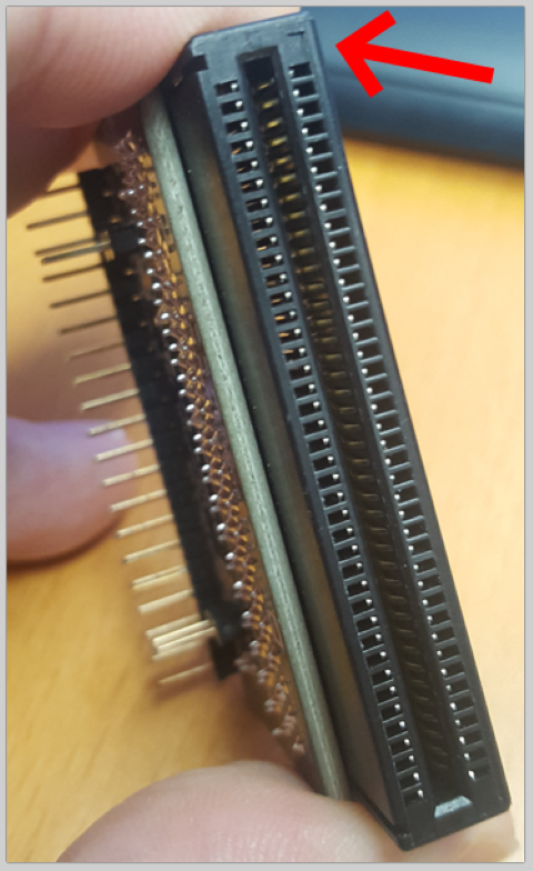
Which way around does the P2 Edge go on the right angle connector (ie. the connector type that has the P2 Edge laying parallel to its "motherboard" when connected)? I have a free connector I am looking at and the P2 Edge board fits in it both ways so I am unsure. Would the P2 Edge components face downwards or upwards when plugged in using this connector on a motherboard's surface? I don't see any pin 1 markings on the connector either. Hopefully @VonSzarvas may know?
Imagine the Pi Zero itself here as the interposer board...
The Edge connector could be put in two places. I'm just not sure which way the P2 Edge faces (up or down), or if it doesn't really matter and you just route its signals as appropriate to the way it's fitted.
Yes that could be much lower profile and neaten things up. Of course that means soldering is required.
Hardest part in general to all this is probably the HDMI routing. The rest of the circuitry could basically just be a prop-plug with the extra connectors and more signal routing. That's all this board needs to be really.
I looked at a list of Pi zero projects and not many of them were suitable for the P2. Also, comparing the P2 to a Pi zero isn't a great idea. They will look at MHz and MB RAM and conclude "just use Pi0." One of the P2's strengths is analog. We should have some analog ports.
Power: USB-C is the future. But there is a case for using microUSB: Making use of the your old microUSB power supplies.
Camera connector: Get rid of it and add USB A plug. Looks somewhat popular as a "Pi Stem". We could just have pads on the board itself for the USB plug. I suppose it could be replaced by a rectangular protrusion from the PCB to save $.50, at the cost of reliability.
HDMI: Back when I was experimenting with HDMI on Rev A, I found that the clock phase didn't matter. At least on my monitor. I don't think a 2 cm length mismatch is going to be a big deal at 320mbps. I would prefer something other than miniHDMI. But full size HDMI is too big unless the P2 was on the back or something. It's just annoying because the adapter costs more than a Pi zero should cost. MicroHDMI has a hidden layer of connections underneath.
It looks like a definite 4 layer board. 6 layers might be better.
On all Parallax boards so far we have followed the tiny arrow on the connector socket to align with the orientation hole of the Edge module. The orientation hole side with the silk ring marking (top/component side) is closest to pin 1 of the Edge socket pads.
The arrow is in the same location for both the vertical and right-angle sockets; at the corner of the socket face.


Thanks VonSzarvas. Looks like I did have it fitted the correct way in my photos then. I didn't even see this marking - was looking on all the other surfaces but this. LOL.
Bummer.
I wonder if the reset recovery time is an issue here, as the read command (03H) seems default/standard.
Did you check a normal read (outside of the boot rom?)
No, didn't try too hard sorry. We'll get back to further testing at some point, but not for a while
We even didn't think about "a proper" orientation of a P2 in the angular slot while designing the robot. Simply: the P2 chip up")
Sounds perfect !!
Yeah, for custom designs it doesn't really matter- just whichever way suits the product design.
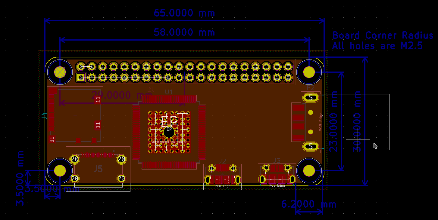
Yeah if the P2 Edge connector is rotationally symmetric then either way could probably be used on a custom board. In the case of this interposer the P2 Edge components need to face up anyway to clear the micro USB and mini HDMI connectors (turns out there is about 0.5 to 1mm clearance there under the P2 Edge above the mini HDMI connector). A fitted microSD on the Edge doesn't seem to prevent a micro USB cable from being plugged in either as I had first feared. There seems to be room. Overall volume without any HAT sitting underneath is about 50x64x12mm which isn't too bad I guess.
That's lots of space for parts under the board, or else some funky graphics or helpful info. I really like the R/A socket for products - nice and compact. That R/A configuration often allows for a bolt through the mounting hole/s to the baseboard too. Can help heat dissipation to some extent, and could make "accidental" removal of the Edge module a tad more tricky, especially with the right sort of evil fixings !
Yes. For a robot that moves and vibrates it is additional protection so the Edge can not go out and escape the robot on its own legs
Or just replace it with a small connector and route the same signals to it that go to the HDMI, USB, micro SD, and PSRAM peripherals. So between this connector and the 40-pin one, many, or most, if not all, of the P2 signals would be available to the user for experimentation.
I'm assuming that if this board became a reality, then perhaps a P2 version of Linux would eventually be available for it. It could probably be advertised as having four cores available for use while running Linux since the other four would be dedicated to the HDMI, USB, micro SD, and PSRAM. But if the user opted to do bare metal programming without Linux installed then all 8 cores would be available.
For Ethernet access the user could plug a USB to Ethernet converter into a USB port.
Or maybe a WiFi module could be installed on the board too, but given the real estate available that probably wouldn't be possible, even if components were mounted on both sides of the board.
Won't happen. As simple as that.
I think the only way it could realistically happen would be as an adapter board. That way Parallax can still sell their P2 Edge which they've already invested in. It's just a Prop Plug in a different form factor with HDMI and USB connectors and the P2 Edge connector...there doesn't need to be much more really. Power can basically feed straight through from microUSB to the Edge. Maybe some FET/USB switch for the USB on P28-P31 and LEDs. It's mostly a routing job if you reuse the Prop Plug design.
You could potentially justify the cost of this adapter board if you don't need to buy an additional Prop Plug assuming you can afford the P2 Edge in the first place. It lets people get going right away without needing to go buy a P2 Edge breakout or JonnyMac board, the VGA/AV or HDMI, and USB expansion modules etc if they just want to do interactive control or emulation stuff directly with the P2 using screens and keyboards etc. Plus people are pretty used to wiring up to 0.1 inch connectors for prototyping and general IO, it's simple enough. There are plenty of prototyping boards from the Pi ecosystem you could use too. Just makes it easy for people IMO. Of course this is not something for everyone, but for a general hacker/maker/experimenter type it's probably reasonably good. Better than buying a P2 Edge and then saying, ok what now?
There would probably be room on an adapter board, but IMO might be much simpler to just bring out suitable connections to the 8 pins of an ESP-01S module in a 4x2 pad pattern assuming the P2 Edge IO regulators could power it at 3.3V. People could then fit their own if they want it. You could probably just share it with P63/P62 too. I've been able to hack the Parallax ESP code to work on one of the these modules and also allow it to reset a P1 for code downloads etc (so the P2 would likely work too). You can buy these modules for 21 cents on Ali these days. (EDIT: Actually turns out that price was for the carrier board available for it, the ESP-01 module itself is approximately a dollar or so).
Update: Also looking at the boards sandwiched together it may in fact be better to mount the P2 Edge under an interposer/adapter board. This way you can access the GPIO signals on top with real HATs and the mounting holes for each board don't interfere quite so much, so you could use the different board holes to mount this into an enclosure or surface a little more readily.
Another way might be to have them both face up but directed outwards from each other (the wider flatter solution below). This allows HATs above and below which is more flexible overall. Lots of ways to do it really.

Flex PCB with castellated 1.27mm pitch half pins. Then you can choose in front, behind, or coplanar...
LOL, bendy.
So, you've listed, very nicely, the exact reasons why I think it won't happen .
.
An adapter board, without needing to go buy a P2 Edge breakout, plenty of prototyping boards from the Pi ecosystem one could use.
There is a good chance it will materialize at some point (when Pi Zero 2s become more available it will make much more sense than now). Just not from Parallax.
There's one connector that just has a single row of pins, Yamaichi PKS019, so routing is simpler and can be one layer
Its the only one I've found like that
Ouch!
This seems to be a heavy misunderstanding. Linux these days needs a memory management unit. And it needs way more RAM to work well. These Linux boards come with 512 MB instead of 512kB of RAM wich is factor 1000 in difference and there is a reason, that the Raspberry 400 Computer comes with with 4GB and 1.8Gigahertz. They have fast first and second level caches, floating point units and graphics engines. P2 cannot compete here in no way.
A non-Linux-microcontroller's strength is for applications, where you need direct access to hardware pins and where Linux gets in the way in an unpredictable manner. P2's strength among them is for projects that are more easily done with more cores than using interrupts. Unfortunately marketing and pricing of P2 is orientated on projects, that can ONLY be done with P2 and of them there exist very few if any. (((And the developers must be prepared to swallow the scattered, incomplete and hard to understand documentation plus the most complicated assembler instruction set plus the limited special language Spin2.)))
The idea to use the raspberry connector instead of the "Parallax specials" is good, so you can use raspi hats! The idea to have the possibility of hdmi (and vga and PS2 keyboard/mouse,) SD-card slot, perhaps USB is good too. I think, that the advantage to use the smaller zero form factor is not too high. As far as I can see, it would be OK use the normal size. No need to wait for anything, @Maciek !
What is needed, is a pricing of a complete directly usable board, that is in reasonable relation to the performance. Parallax was able to sell a P1 project board for 35$. (Was it ~25$ before the miraculous jump of prices?) Given the price difference P2-P1 and the need for the additional power supply plus at least SD-card slot, a project board <45$ seems to be possible. As far as I understand, smaller boards can be manufactured significantly cheaper. Probably some large volume production facilities have to be used? The question is, if/when will Parallax go this step to enable the usage of P2 for new/more costumers, @"Ken Gracey"? (I never wanted to make you angry!) The idea to wait any longer seems not to be good, because now there are boards in sight, which have more than 1 core: the super fast M7+M4!
Christof
Right, but then there's this: https://forums.parallax.com/discussion/175122/linux-on-p2
So it doesn't appear to be a matter of if it can be done, but rather if it's practical, functional, and useful. Seems to be iffy at best (being quite charitable here). But given the superb talent of those on this Forum, who knows what they can achieve.
Correct. For me it's not really an issue because I prefer to write code that runs bare metal without having to deal with an operating system. But I know there are those who like Linux, so that's why I mentioned the possibility.
Yes, I think the Raspberry Pi form factor would be a reasonable replacement for the Prop2 Eval Board. Do I think it is likely in the near future (if ever)? No, that's why I bought a couple more Eval Boards today.
Price is a major issue isn't it? You can have a really nice board, whether it be a Raspberry Pi configuration or whatever, but if the cost is high the market will be limited. Clearly the Raspberry Pi Foundation well understood that. But I wish you good luck in trying to get ahold of any of their boards right now.