

P2 16-bit PWM output on a smartpin!
 enorton
Posts: 144
enorton
Posts: 144
in Propeller 2
Hi All,
I need to create a 16-bit PWM with an adjustable frequency period of 20 to 35 kHz and a duty from 0 to 100%. Does anyone have C examples on how to do this? I tried the Saw version of the smart pin pwm output and it doesn't seem to output anything ![]()
Any help is greatly appreciated ![]()
Thanks,
Eric
Comments
The smartpin modes need
P_OEto be set to actually output anything. Just post what you tried to do.An example in FlexBASIC, but the configuration is the same in all languages:
https://forums.parallax.com/discussion/comment/1530975/#Comment_1530975
Andy
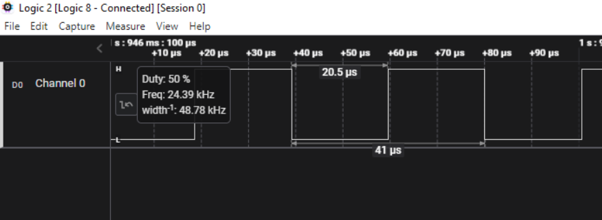
As Andy points out in the example he referenced, your PWM frequency maximum is going to be system frequency / resolution, so if you're running at 200MHz and want 16 bits of resolution, your PWM frequency is gong to be about 3kHz. If you can tolerate a resolution of 13 bits, you can get ~24.4kHz PWM using 200MHz system clock.
I use Spin, but I think Catalina has direct equivalents.
Note that it's the wypin instruction that sets the output duty-cycle.
LA capture:
Is this ultimately being R-C filtered for DAC emulation? Say, via an optocoupler.
If so then I recommend changing the mode of modulation and using PDM (Pulse Density Modulation) instead PWM. PDM has notable better performance at the filter.
Use smartpin mode
P_NCO_DUTY(%00111) for PDM output.Ah, this is interesting. I need to be able to adjust the frequency pretty accurately and the duty cycle. The range is actually 0 to 1000 so I could get away with 10-bit and this would give me the range I am looking for plus some extra for the frequency with a maximum of 293 khz which is way over what I need. I just need to adjust in a frequency range of 20 khz to 35 khz and 0 to 1000 duty cycle.
Don't we have some dithering trick to provide 16bits at higher frequencies?
Craig
Ah, @evanh already covered this in the other thread
I am filtering for +/-10v. Will test this option as soon as
Craig
???
Craig
In my Spin PWM object I allow the user to pass the PWM frequency and the 100% duty cycle value. You might want to do some experimenting to determine if rounding errors will cause issues with your desired accuracy.
Yeah, Chip should have used duty mode for dithering the 8-bit DACs.
I only recently discovered, myself, how much better PDM is when I was making a Vref for current setting with the Prop1 counters. I had a PWM operating and wasn't impressed with how big a capacitor I needed to get the ripple right down to 1.0 mV. I knew that duty mode could be done 100% within the counters and didn't require any Cog intervention ... so gave that try in the hopes it would be at least as good as full PWM.
Only after experimenting with it did I realise it was performing way better. I then decreased the capacitance and it was still no ripple while responding much faster. No longer needed the large post-adjustment settling delay in software!
There is a prescaler and a period definable, so at 300MHz nominal, you then have 15000 steps at 20kHz and~ 8571 steps at 35kHz
If you wanted a fixed 1000 steps, you could use the prescaler for a more coarse span between 20k and 35k (roughly 7 steps)
If you need even finer adjustment, you could dither the DUTY.LSB or PER.LSB in SW every period
I remember your excitement but I was left with the impression that it was a P1 thing only.
I have ripple but it's insignificant for a closed loop servo with a PID running at 4KHz.
My interest in 16bit resolution is purely specmanship because the big-name motion controllers can do this. There is even one with an 18bit motor command. Would need an external DAC for that.
Craig
Is DC_MAX the duty cycle max? Ill give this a shot and let you know. Thank you for providing an example
Yes. In your case it would be 1000. In case it's not clear, the x register holds the system ticks per unit in the low 16 bits, and the number of units in the period in the upper 16 bits.. After this setup you write the units with wypin().
Ok thank you. I will give it a whirl in a bit and let you know
Jon,
THANK YOU SO MUCH!!! Your code is working beautifully
On to the next hurdle. Thanks again!!
Glad to help.
I really appreciate your help and everyone else's help as well. I'd be lost without you all!!
16-bit PWM extended DAC works up to ~1.25 MHz and has exactly this frequency (CLK/256) and its higher harmonics to filter off
For accoustic band you can still use a noise shaper converting 24 bit to 16 bit. The limit is analog noise that is low there (SNR >100 dB) , but not as low as -144 dB
Holy moly, this sounds pretty amazing but what shape is this waveform?
I am not with my P2 right now so unable to test.
Craig
P2 16-bit PWM extended DAC uses PWM to switch between 2 8-bit values at CLK/256. The noise generated with this method is CLK/256 square wave with variable pulse width. Its spectrum is the main frequency (CLK/256 = 1.25 MHz at 320 MHz clock) and its harmonics, at about -48 dB. As 1.25 MHz is far above accoustic, it is easy to filter off, even by an amplifier itself.
I experimented with these DACs using 3-bit "sine wave" (it doesn't look as a sine wave any more at 3 bit resolution), connecting the P2 to the amplifier at full volume. You can then hear a sine wave, a quantization noise and a background nouse (P2 itself, the amplifier input). This background noise was much lower than the quantization noise hearable with the sine wave. The conclusion is: the P2 can output the sound at the SNR >100 dB. Maybe 110. I have no proper measurement equipment, these are conclusions from the experiment.
16-bit DAC has maximum SNR at about -96 dB, so there is a possibility to enhance this. We have a P1 audio driver using the oversampling and the noise shaping. The noise shaping is a filter that changes the quantization noise spectrum so its energy goes to higher (=ultrasonic) frequencies. Using easy to implement second order filter you can add 15 dB to the SNR for every sample rate doubling. The trick is: the noise is still here, but its energy is concentrated near sample rate/2 (this means about 600 kHz for a P2) and this is not hearable and can be filtered out.
If you have 16 bit signal at 44 kHz, you have this theoretical -96 dB, but at 88 kHz you have -111 dB and at 1.25 MHz there is -168 (!) dB. Of course we cannot get 168 dB dynamic range from a P2 output: it has its noise at much higher level, but now this analog noise is the limiter, and not a DAC quantization.
We even don't need to implement the noise shaper: oversampling itself adds 3 dB to the SNR for every octave, so at 1.25 MHz 16-bit DAC's quantization SNR is at about 110 dB (for accoustic frequencies) without any tricks.
Is there a write-up of this Prop1 solution? The analogue circuits in particular.
Quick forum search gave me this:" https://forums.parallax.com/discussion/141285/return-to-duty-dac-oversampling-noise-shaped-player
but there was more topics about this algorithm
Edit: also this: https://forums.parallax.com/discussion/141346/yet-another-wave-player-now-nco-based-and-noise-almost-free#latest
Apologies if I appear a bit dense but if it's not duty-mode, what is it? I won't get to my P2 until tomorrow so I'm unable to hook the scope up to see what we get.
Assuming that this mode works for my +/-10v opamp filter, would it be reasonable to assume that the higher frequency would require an even smaller capacitor for a given amount of ripple?
Craig
@pik33
Apart from the bit-depth, does this mean that the P2 is capable of similar performance to that of commercial audio-interfaces? The SNR certainly seems to be up there
Craig
Keep in mind the DAC is still 8-bits, the modulation just wobbles the LSB to allow interpolation, but that is only as good as the absolute precision of the two end-points.
Linearity and thermal drift are unlikely to be anything like the LSB infers, but for some applications that may not matter. If it is closed loop control, or just someone's ears, that may be ok.
The DAC also uses VCC as reference, so very clean regulators and dedicated pin-group usage would be needed for best performance.
eg 16 bits is 50uV LSB
I see ADI have 3.0V 70mA precision reference parts
https://www.analog.com/en/products/adr3630.html#product-overview
ADI also have very low noise, high PSRR, current-reference regulators
https://www.analog.com/en/products/lt3042.html#product-overview
Of course, you pay for the top-shelf performance specs.")
This is the best audio DAC I experimented with. (however I have not enough money for the audiophile stuff to compare)
ADC is not that good, and that's why you can buy the external ADC board for a P2. I haven't this board (yet) so I don't know what quality it is. The DACs however are excellent.
I think Chip said the linearity of the DACs are good for at least 13-bit effective.
As the name indicates, P_DAC_DITHER_PWM uses PWM mode dithering rather than (PDM) duty mode dithering. PWM mode also requires more transistors than NCO duty mode so using duty mode would've been cheaper as well as better.
It allows the use of a smaller capacitor, yes.
Thanks. Some reading for me ...