

128 LEDs, 64 Buttons on P1?
 T Chap
Posts: 4,260
T Chap
Posts: 4,260
in Propeller 1
Using LCD became problematic on P1 when parking bitmaps in the DAT due to not enough memory. You can do nice graphics on P1 with Newhaven Cap Touch LCD but you can only put so many graphics. I have a case where I want a matrix of buttons 8x8. Above each button I need 2 LEDS, 0603 SMT. Green and Red. That means 128 LED's. I can dedicate a P1 to this task. 8x8 buttons is easy with 16 pins in a XY matrix. 128 LED's is a bit more work, I have a 16LED driver that works well, but that means 4 LED chips.
Any ideas on how you would do this? Honestly it starts to make sense to go back to a 7" LCD but the 100$ cost or so is a bit much for the product.
Comments
Looks like you're going to have to do some Charlieplexing.
Mike
How many I/O's do you have available?
For Charlieplexing you take the number of I/O's times the number of I/O's minus 1 to determine how many I/O's you will need.
So for 128 LED's you would need 12 I/O's which would actually allow for 132 LED's. 12 x 11 = 132
Note1: With Charlieplexing only 1 LED is allowed to be ON at any given time but you can sequence the LED's so that POV appears that many LED's are on at once.
Note2: Use a current limiting resistor on each I/O that is half of the required LED for a single LED and divide that by the number of LED's you plan to display all at once. i.e. if a single 1.7V LED requires 10ma @ 5V, then the current limiting resistor for a single LED would be ... (5V - 1.7V) / 10ma = 330 Ohms ... So each I/O leg would need a 165 Ohm resistor. Now if you wanted 30 LED's to appear ON at once, then divide 165 by 30 and each I/O should have a 5.5 Ohm resistor. Just don't let your program stall and sit on one LED or you might over current the LED.
Note3: You can also apply Charlieplexing to switches, but each switch must have a diode in series with it in order for it to work.
Have you considered using WS2812 LEDs instead of standard LEDs? With the former, you could replace both LEDs with a single pixel (if there is no need for both to be on at the same time). You can control all of the pixels with a single IO pin, and even tune the colors and brightness. There are drivers available (I wrote one) that will save you the trouble of writing a Charlieplex driver for that many LEDs. As Beau points out, there are serious considerations with Charlieplexing.
Even if you use 16 pins for your button matrix, your IO requirements are only 17 pins, something you could done with a Propeller mini.
Have you looked at Nextion HMIs? They're reasonably priced and all the graphics assets are stored in their flash, so there is little burden on the Propeller. Getting data to and from the Nextion is a simple serial connection. I've deployed two commercial products (okay, one hasn't been released, but it did make an appearance at a trade show) that use Nextion HMIs. In both cases the customer response was excellent -- everybody knows how to use a touch screen these days.
This is an idea I created for a friend who runs escape rooms; it's a countdown timer. The Nextion Enhanced and Intelligent series have eight IO lines, so we can run this without an external processors, but in most cases we use a P1 to connect to a command and control system via XBee or RS-485.
Ironically, this [older] demo simulates standard red and green LEDs! It's impossible to see in a still image, but the buttons are animated. When connected to the Nextion Expansion Board the device will "chirp" (through a piezo buzzer) any time a keypress results in a display change.
I created the graphics with Inkscape (one of my favorite freeware tools). If you have a bit of time, download the Nextion editor (it's free) and give it a go. You can simulate the device and test your Nextion code (it looks a bit like C, but is limited being a scripting language) -- no hardware purchase required (screen grabs are from the Nextion sim). If you decide to try it, I have P1 and P2 Nextion objects that you're welcome to use.
Thanks! It's great seeing the ideas, because that simplifies this a lot. My first though is to use small SMT tactile buttons, easy enough to do 8x8 matrix for those. I have done WS2812 LED and have a reel of 1000 sitting in a box! I have ran 56 and that is actually a great idea, already have JM code that works great and no learning curve there. I can either use different colors as needed or have different modes to solve the issue of only one LED vs a red and green separate. The Nextion looks interesting but I like the cost of 64 LEDS that are very cheap and no learning curve, it's around $100 for 1000 LED's last I bought them maybe less now. I also just realized I don't need 64 buttons, I can use 8 buttons in a row, with a 8 selector buttons that chooses which Rows 1-8. I don't need 64 buttons at a time. Many thanks I think it doesn't get any simpler than this.
Your arguments are valid. That said, I'm getting asked by my clients for a more modern approach -- and something that can be updated. With the Nextion (or similar HMI), you can send an update to the client that they can drop onto a microSD card. Having no idea about your app, I knocked together a simple graphic that shows a 8x8 matrix with RGB "buttons." For the Nextion you'd need one background graphic, and four button graphics (one for each state/color). With just two routines, you could send a message to the P1 that tells it which button was pressed, and a message set from the P1 could set any of the buttons to the a specific color. The latter would require two messages from the P1: one to set the channel/color variable (needs to be a single value, e.g. 643 would set channel 64 to color 3), and the next to run the subroutine. Yeah, programming the Nextion is a little different, but doesn't take long to pick up and gives you a lot of flexibility.
Just my thoughts. Good luck with your project and let us know how it turns out.
Great idea for Ws 2812b
It’s alive
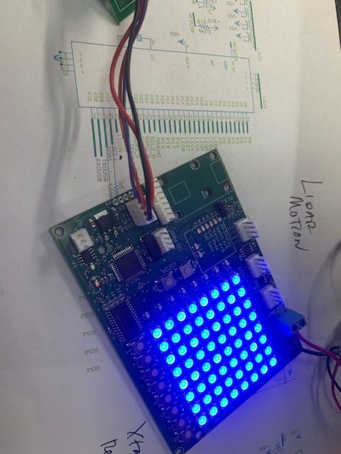
Looks nice, too.
So does your GUI
Don't know if this is of any interest but I found a cool program for GUI creation and this is what I have so far:
https://youtu.be/0OK4x7Ob_eg
I am handling the actual animation with the RFO BASIC! interpreter (Android) but maybe the same can be done with the Nextion displays(?)
Knob Studio zip is too big to upload so:
https://dropbox.com/sh/4a4y5not3x7yy9r/AAAzTqFPp6zCZ1UYHnpUL-NUa?dl=0
Craig