

Need help with modifying jm_ez_spi.spin2
 jay_harlow
Posts: 43
jay_harlow
Posts: 43
I'm trying to extend jm_ez_spi.spin2 to support a variable number of bytes, part of my can bus project. attached is what I got,
tx_serial seems to work (I need to read & pass the value at the pointer, not the pointer to wypin)
rx_serial I'm at a total loss...
Attached files removed; I forgot to update the author info, causing confusion on which object I was modifying; again, I apologize for any confusion this caused.
Jay
Comments
Please see my PM.
There was no need to modify that library -- libraries are supposed to be atomic; you've now made it somewhat specific (and a mess).
IMO, you could add these methods to YOUR APPLICATION (i.e., don't modify the library) and be moving along.
pub tx_cmd(cmd, bits)

  spi.shiftout(spi.MSBFIRST, cmd, bits)


pub tx_buffer(p_src, count)

  repeat count
    spi.shiftout(spi.MSBFIRST, byte[p_src++], 8)


pub rx_buffer(p_dest, count)

  repeat count
    byte[p_dest++] := spi.shiftin(spi.MSBFIRST, 8)
Tip: If you think you need to modify a library written by someone else for a specific project, you don't; you need to add support methods to your application.
My bad, please accept my apologies.
I named mine jbh_ as opposed to jm_ which seems to be the convention. I unfortunately forgot to change the author info
Important safety tip, change the author information when cloning an object
I had code similar to yours as my first solution; I'm changing my copy to learn how the testp opcod works for smart IO pins
maybe my question should be how to leverage the testp opcode and "Synchronous Serial Transmit (%11100)" ands "Synchronous Serial Receive (%11101)" smart pins
thank you for your time
Jay
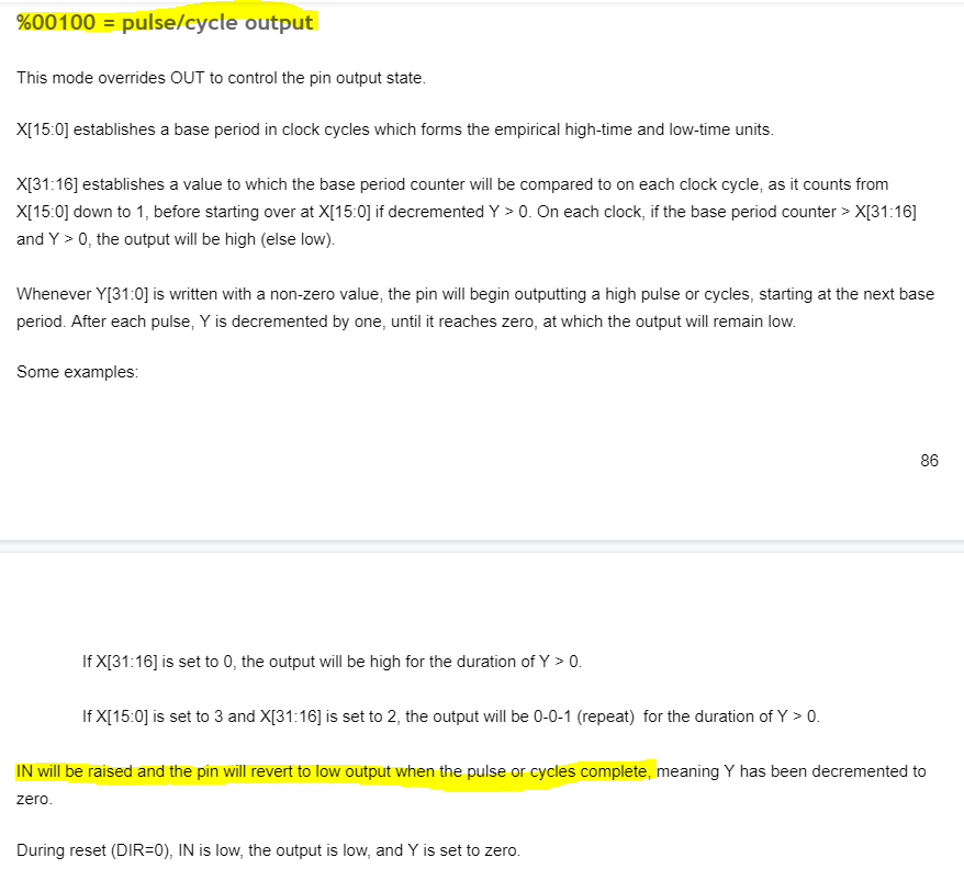
Some smart pins raise their IN bit to indicate a process is finished. I use this feature on the SCLK pin because the P2 controls the SPI clock. From the docs
The synchronous RX feature will do the same thing when the correct number of bits has been received, but using this seems to make sense when an external clock is used (P2 is SPI slave).
Let me suggest that you write separate test code to learn new features. I've been helping a friend (JonyJib) with a new feature to a big P2 project and we developed the new feature code completely outside the application to ensure everything works properly. It's easier to fold in now that the new code has been vetted.
I see value in it ; calling ez_spi in a loop cauaes a lot of duplicate code to be executed MCP2515 has sequential read / write commands, which means you can call one command and pass 10or more parameters along; there are two commands that will return an infinite number of commands. they raise their in bit allows overlapping IO
agrreed,
how does yours differ?
I wrote a P1 driver for the MCP2515 that has these two "SPI" methods:
pri spi_write(txval)

'' Write byte to MCP2515

  txval ->= 8                                                   ' prep for MSB output

  repeat 8
    outa[mosi] :=  txval <-= 1                                  ' txval msb --> MOSI
    outa[sclk] := 1                                             ' clock high
    outa[sclk] := 0                                             ' clock low


pri spi_read : rxval

'' Read byte from MCP2515

  repeat 8
    rxval := (rxval << 1) | ina[miso]                           ' MISO <-- rxval msb
    outa[sclk] := 1                                             ' clock high
    outa[sclk] := 0                                             ' clock low
It was used in a commercial HVAC system and we never had problems. Maybe our requirements were simpler than yours (it was about 10 years ago). If you want to go beyond what my simple SPI library is doing, I suggest that you just add smart pin control into your MCP2515 object, especially since you're usually doing byte operations, and always MSBFIRST.
Then you could create a method like this (UNTESTED!!! [here, but I've done similar things in other projects]).
pub write_read(p_src, p_dest, count) | outval, inval

  repeat count
    outval := byte[p_src++] rev 7                               ' read, reverse for MSBFIST output

    wxpin(mosi, %1_00000 | (8-1))                               ' configure mosi bits
    wypin(mosi, outval)                                         ' load value
    pinl(mosi)                                                  ' enable mosi
    pinf(miso)                                                  ' reset miso
    wxpin(miso, %0_00000 | (8-1))                               ' configure miso sampling/bits
    pinl(miso)                                                  ' enable miso
    wypin(sck, 8)                                               ' start clocking data
    repeat until pinr(sck)                                      ' wait for clocking to finish
    pinf(mosi)                                                  ' disable mosi

    inval := (rdpin(miso) rev 31) & $FF                         ' get inval, reverse

    byte[p_dest++] := inval
If you point the output and input buffers at longs you could write and read up to four bytes into a variable. Or you could use larger byte buffers and point at them.
I keep my projects in folders separated by client, and their specific projects underneath them. My generic objects are in the Propeller Tool Library folder. On rare occasions I write an object that is project specific; that will go into the specific project folder.
When things get tricky, I will add a "work" file the project file that I can pop out to and do testing in, separated from the app. This lets me vet elements of code before use.
I'm looking for this, or something real close to it
https://github.com/parallaxinc/propeller/blob/master/resources/FPGA%20Examples/smartpin_serial_turnaround.spin2
only p2, not fpga; following your conventions... I'm using ez_spi as a starting point as its most of what I need; now I need to dovetail the .full and .recv loops into ez_spi;
I need to back up and look at this (smartpin serial turnaround) closer; to get a better idea what this is doing ;
Thanks for the continued help
Jay
and come up with a better name for it....
To me it makes no sense to use a generic SPI library for your MCP2515 when you can be more code efficient by embedding smart pin setup (CPOL 0, 8 bits) into your code. In post #6 I showed how you can write and read SPI at the same time -- the MOSI and MISO pins are controlled by the SCLK pin. It works nicely. By passing a pointer and count, you can write/read any number of bytes.
I am not looking for alternate solutions!
I am looking for guidance on creating a solution that uses TESTP and raising IN.
Synchronous Serial Receive (%11101)
When a word is received, IN is raised and the data can then be read via RDPIN / RQPIN. The data read will
be MSB-justified.
Snchronous Serial Transmit (%11100)
Each time the buffer is advanced into the shifter, IN is raised, indicating
that a new output word can be written via WYPIN
Thanks
Jay
[Deleted]