Anti-aliased square wave synthesis demo (BLIT)
 Wuerfel_21
Posts: 5,862
Wuerfel_21
Posts: 5,862
Welcome to today's pointless experiment!
Ever want to synthesize some square waves but don't want to run at absurdly high sample rates to get rid of the pesky aliasing?
Frequency aliasing occurs in a simple NCO-type synthesizer because the edge of the waveform is rounded onto the next closest sample point when it really should be somewhere in-between.
Luckily, it is possible to generate such inbetween-samples edges by considering our square wave as the running sum of a pulse train of alternating polarity (ie. one pulse makes one edge). Synthesizing an inter-sample pulse in turn is rather easy, since that's just evaluating a sinc function on the samples surrounding the pulse (in theory, this would be an infinite amount of samples in both directions, but in practice we can cut it off after a few samples).
This technique is called Band-Limited Impulse Train.
The sampled sinc looks like this:
Notice how when the offset is an integer, the sample points line up with the zero-crossings of the sinc function and we get the good old lone spike.
Integrated it looks like this:
Now, the secret to doing this in real time is to precalculate these sinc impulse samples for a few fractional offsets and every time the oscillator generates an edge, pick the closest one to how far the edge lies in the "past" and add it into a buffer of same size. For each sample produced, this buffer is shifted over by one, shifting in zero at the tail and summing onto the head. The head of the buffer then becomes your output value, the running sum of all pulses. (This obviously incurs a delay of half the buffer size between oscillator and output)
Perhaps a poor explanation, but oh well.
Attached is an example implementation. Set NO_BLIT to true to hear what a normal non-antialiased oscillator sounds like. Pretty big difference, right?
Things to further look into:
- How big do the samples really need to be? Currently they're 16 long, but could probably cut down to 12 with little loss.
- How many impulses are really needed? Currently I'm using 16, but more only really increase memory use. Effectively this is a multiplier of the sample rate, so doubling the sample rate should mean that only half the impulses are needed for an equivalent result.
- Since MULS only cares about the bottom 16 bits, two impulses could be interleaved to halve the table size
Comments
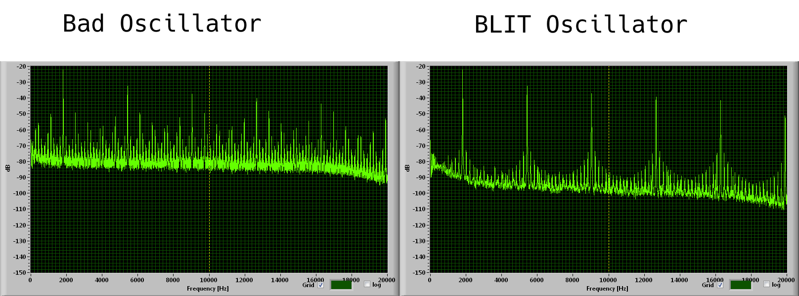
Additionally, here's what the spectrum analyzer in my crappy soundcard scope software says about it:
Interesting…. Never heard of this..
Google found this https://www.metafunction.co.uk/post/all-about-digital-oscillators-part-2-blits-bleps
Sure it’s not BLEP?
Also, are you saying you can hear the difference in audio frequency square waves with P2 at MHz frequency?
I’m kind of surprised at that…
It sure is BLIP, since the entire waveform is formed from the pulse lookup table. BLEP adds a residual on top of a normal oscillator. The latter is a bit faster, but doesn't work as good [citation needed] at higher frequencies since the residual gets truncated when the (half) period is shorter than the table.
And yes, there's an obvious difference. Try it for yourself.
Yes there is a very audible difference in my simple amplified speaker setup from the A/V board and I'm no golden ear type. Nice work Ada.
In the attached example, the sampling frequency is 44100. At 44100 the aliasing level is, of course, catastrophic for the frequencies over 1 kHz, and still hearable for lower frequencies.
At 1.25 MHz the effect should be much less noticeable. The aliases for standard range of sounds used in music will be at the level from -50 dB (4 kHz) to -90 dB (40 Hz)
The described method allows to use lower sample rate and still avoid too much aliasing. We are spoiled here with our DACs working at 16 bit resolution and over 1 MHz sample rate. Other microcontrolers, including a P1, don't have such luxuries.
Here's a de-popping example that softens the initial startup. Generally only has impact on first run after a power cycle.
It assumes capacitor coupling for audio use ... gently charges the capacitor on each DAC pin until floating voltage is at 1.0 volts before handing over to driving the DACs.
This paper discusses BLIT and an alternative to Sinc:
https://www.researchgate.net/publication/319876490_LP-BLIT_Bandlimited_Impulse_Train_Synthesis_of_Lowpass-filtered_Waveforms
Interesting. I hadn't heard of this before because in communications systems we try not to make anything close to a square wave.
There are a lot of ways to efficiently generate these waves.
Options 1 and 2 requires that the appropriate harmonics to be explicitly added. Option 3 controls the frequency response by scaling the input to the sinc() function. Generating a "square wave" with the harmonics limited to well below the Nyquist limit or the human hearing limit might be an interesting artistic effect.
It actually needs more than one sinc per sample. If the wave period becomes less than twice the window size, the impulses start to stack up on top of each other.
The other benefit of the table approach is that the table can be calculated to avoid rounding error. One can also prevent it from building up by applying a high pass filter (my example actually does this, despite not having any error, since the tables all add up to 7FFF)
Several years ago I wrote something I called PC-Softsynth. A program on a PC that can edit and play music created in 8-bit Atari program "Softsynth"
8-bit Atari Softsynth used 11 kHz, 4 bit sampling and 256 bytes long, 4-bit samples. So I (1) resampled them to 16 bit, 1k samples (2) FFT (3) left first 15 harmonics (4) resynthesize the samples as sum of these 15 harmonics.
The PC Softsynth is yet another thing to move to a P2.
The result: http://eksperymenty.edu.pl/images/mp3/wodo.mp3
Original Atari tune: