

HF Spectral Purity Comparison: P1 vs. P2
 Phil Pilgrim (PhiPi)
Posts: 23,514
Phil Pilgrim (PhiPi)
Posts: 23,514
I've made several assertions in this forum suggesting that the P1 might be better than the P2 for generating RF signals due to its asynchronous PLL outputs, and the fact that the P2's outputs are synchronized to the system clock and, thus, subject to more jitter. So I decided to test this hypothesis, given the availability of @Wuerfel_21's very short radio_buzzer program for the P2 (FM_DEVIATION set to 0 -- carrier only). Putting the cart before the horse and stating my conclusion before presenting the evidence, I was dead wrong.
The test consisted of two parts for each processor: generate a 20 MHz signal, and generate a 21 MHz signal. Here's the result (waveform and spectrum analysis) for P1's 20 MHz output, generated by the program attached below:
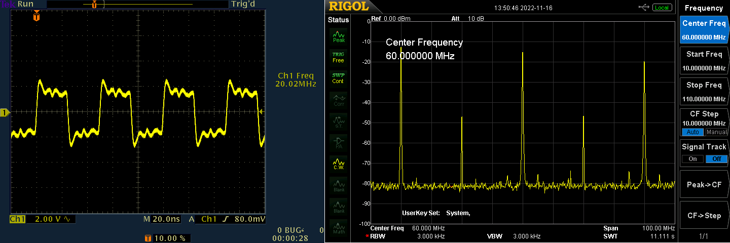
Because 20 MHz is just the 80 MHz system clock divided by four, you expect to see a clean square wave (subject to overshoots and ringing due to scope-lead inductance) with no jitter. This is evident in the spectrum with obvious odd harmonics (and some even ones, too -- hmm).
Now, try the P1 at 21 MHz:
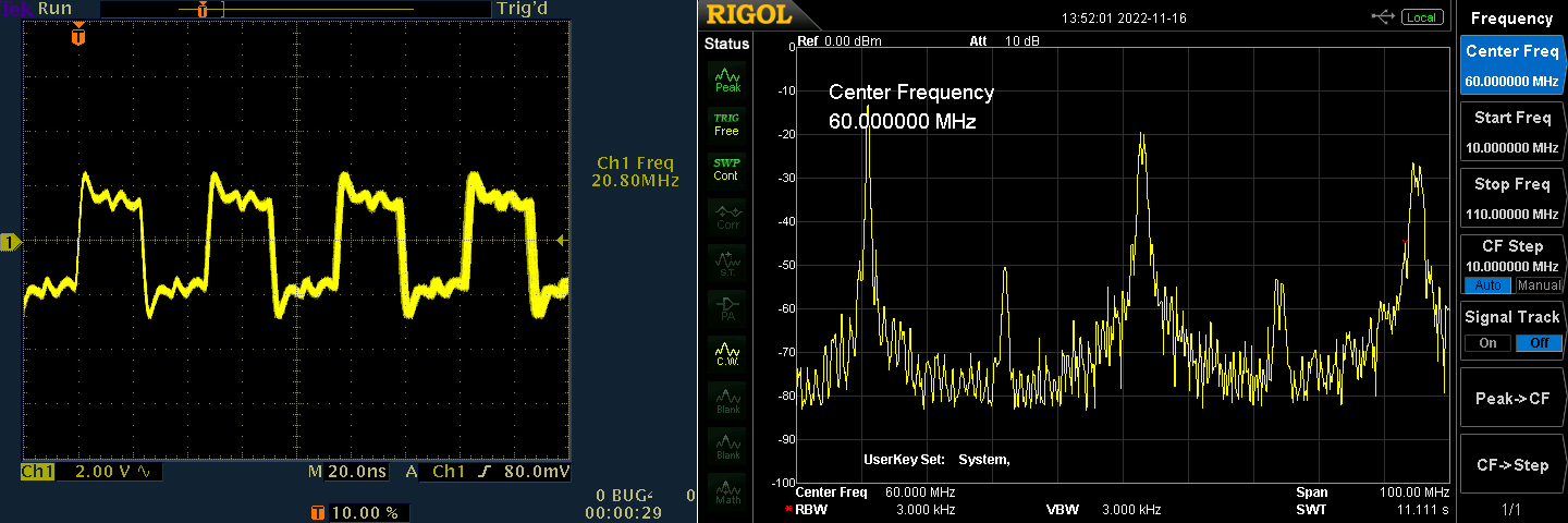
Yuck! You can actually see the jitter in the scope trace as a blurring towards the right. The spectrum is downright ugly! I would have expected the loop filter in the counter PLL to do a better job reducing the jitter, but it did not. Apparently, its time constant is too low for that.
Repeating the same test with @Wuerfel_21's program on the P2, here's the result for 20 MHz:
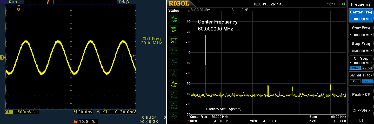
Again, because 20 MHz is the 320 MHz system clock, divided by 16, you expect the spectrum to be pretty clean, and it is. Notable, also, is that the harmonics are much diminished compared to those of the P1. That's because the P2 outputs approximate sine waves, rather than square waves.
Now, let's look at what happens when the output frequency is set to 21 MHz:
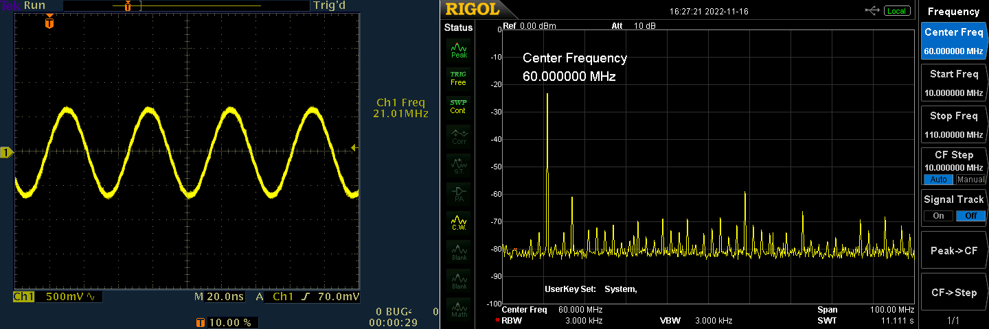
Now, there's a lot of garbage in the spectrum, but not as bad as that from the P1.
But wait! There's more! The P2 allows you to set the system clock frequency over a broad range, so let's set it to 21 MHZ * 16 = 336 MHz. Here's the spectrum:
Much cleaner!
So, to summarize, the P2's ability to output high-frequency sine waves gives it the capability to attain a cleaner spectrum than that of the P1, which outputs square waves. That said, however, neither chip should be considered as a candidate for transmitting over the airwaves, although use as a local oscillator in a receiver cannot be dismissed (rf: here). I believe that either chip, in conjunction with an LC VCO, controlled via a varactor in a programmed digital FLL could be used to produce transmit-ready waveforms.
-Phil
Comments
Very interesting Phil
Some years ago I had a look at the P2 DAC linearity which exhibits a slight s-curve deviation from nominal values. I think that constraining the sine output amplitude/range might improve things - especially avoiding the top and bottom 10% of levels, or perhaps just using between levels 120 and 190 for greatest linearity. I don't know whether this is easy to test with what you're doing at the moment. I was thinking it may be possible to correct these small errors with an adjacent pin and external resistor to tug the DAC output closer to its ideal value
Phil's scope plots show only 1.6 Vpp or so. So it is indeed operating in the middle range.
I still think that a lot of that distortion is from the chroma modulator. https://forums.parallax.com/discussion/174719/chroma-modulator-blues I modified the radio buzzer program to use DDS mode instead.
I won't be able to check this with a spectrum analyser until at least tomorrow.
Using your DDS spin2 program with FM_DEVIATION set to 0, this is what I got generating a 21 MHz signal with a 320 MHz system clock:
It's much cleaner than the one produced under the same settings with the chroma modulator.
-Phil
So, DDS is cleanest.
I suppose outputting a 16 MHz sine from a 320 MHz clock would have a lot of harmonics, because the waveform would have a consistent pattern of the same 20 output samples.
Thanks for doing all those tests, Phil.
I noticed in playing around with ultrasonic transducers that because they are narrow-bandwidth, they are very phase-stable.
Here is a short video I made showing this:
I'm thinking that outputting, say, a 4 MHz sine wave and then picking it up across a 4 MHz crystal would provide similar phase stability from which, maybe, conductor length could be determined.
4 MHz has a wavelength of about 75m. The Goertzel circuit should be able to resolve phase to a very small fraction of a degree, so maybe distances of millimeters could be resolved.
Yup, but it's not terrible:
The small peak just before the 5th harmonic is puzzling, though. It disappears when I disconnect the P2.
-Phil
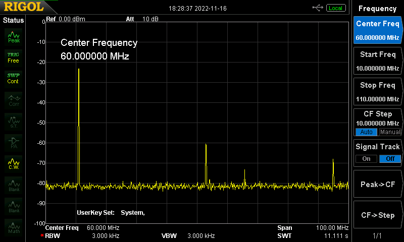
I zoomed in to see how much energy the sidebands contain. (This is with zero modulation, remember.) Looks like they're 50 dB down from the carrier peak:
BTW, the reason the carrier peak is not at zero dB, is due to the DC (0 Hz) component, which is at zero.
-Phil
Here are the spectral purity requirements for Amateur Radio transmitters:
47 CFR 97.307(d) For transmitters installed after January 1, 2003, the mean power of any spurious emission from a station transmitter or external RF power amplifier transmitting on a frequency below 30 MHz must be at least 43 dB below the mean power of the fundamental emission. For transmitters installed on or before January 1, 2003, the mean power of any spurious emission from a station transmitter or external RF power amplifier transmitting on a frequency below 30 MHz must not exceed 50 mW and must be at least 40 dB below the mean power of the fundamental emission. For a transmitter of mean power less than 5 W installed on or before January 1, 2003, the attenuation must be at least 30 dB. A transmitter built before April 15, 1977, or first marketed before January 1, 1978, is exempt from this requirement.
47 CFR 97.307(e) The mean power of any spurious emission from a station transmitter or external RF power amplifier transmitting on a frequency between 30-225 MHz must be at least 60 dB below the mean power of the fundamental. For a transmitter having a mean power of 25 W or less, the mean power of any spurious emission supplied to the antenna transmission line must not exceed 25 µW and must be at least 40 dB below the mean power of the fundamental emission, but need not be reduced below the power of 10 µW. A transmitter built before April 15, 1977, or first marketed before January 1, 1978, is exempt from this requirement.
-Phil
I was about to say it looks like it was about 50db down. Is that without a LPF? That's pretty darn clean! I wonder how clean it is at 144.39Mhz? (APRS frequency in North America) I know that is a bit of a stretch from 50Mhz.
It could definitely be used for WSPR.
Yes.
About the same, although there's sideband splatter over a much wider range about 55 dB down from the peak. Also I can't get the frequency to be exact. It's coming out to 144.386666 Mhz.
For VHF work, you'd probably be better off generating a HF signal and mixing it up to the 2m band.
-Phil
BTW, this is what a 144.39 MHz signal would look like if my scope had ten times its 300 MHz bandwidth:
I obtained it by dividing both the system clock frequency and output frequency by ten. I guess this explains the wider sidebands.
-Phil
Actually, things at VHF frequencies are really bad. Here's what I get when I zoom out with the program generating a nominal 144.39 MHz signal:
The first peak is at 144 Mhz; the second, 175.5 Mhz.
-Phil
Phil, I wonder if adding a small amount of random FM or AM could dissipate those extra peaks.
Yep, aliasing is to be expected. Frequencies over the 160MHz nyquist limit should be filtered out. Though the filter would need to be really steep to go this close to the limit.
Adding AM would just create sidebands without affecting the extra peaks. I tried adjusting the output frequencies a little to see if the extra peaks moved much. They did not.
I'm pretty sure the peaks are a consequence of the output frequency's relation to the system clock frequency, with some kind of beat phenomenon happening. For example, if I move the system clock frequency closer to twice the output frequency, the peaks become closer together. But at twice the output frequency, the output disappears entirely.
In any event, there seem to be two possible avenues to take for VHF transmission:
-Phil
Or do both. That could be a very useful bit of mischief indeed.
A LPF should drop that harmonic at +30MHz 50db down. The in-band purity is the greater concern.
PS: That is a mighty tall spur.
The 175 Mhz is an image frequency. If the sysclock could be increased to 330MHz, the image frequency would increase to 186MHz. That might be pushing it.
I did some simulations to see It suggests that 178-186MHz sysclock is optimal for generating 144MHz while placing the least burden on the bandpass filter design. Basically we are using that image signal for our desired output instead of filtering it out.
Unfortunately using the 185MHz sysclock causes a loss of 8.6dB of output power due to the sinc function.
The ideal solution would be to increase the sample rate. Maybe we could use 2 dacs and put a delay line between them. But it might actually be better to use that coax as a filter instead.
There are differences in the propagation delays of the pin circuits, due to the slight variations in their internal positioning along the pad ring.
Also the pins near the corners of the silicon dice present increased series inductances, as compared to the ones near the center of each side, due to differences in the lenght of the gold wires that connects each phisical pin to the pad ring.
Depending of the amount of delay one needs to add between any two of them, perhaps most part of it is still there, ready to be leveraged.
If a special pcb is to be considered/designed, the fact that the Vios are segregated in groups of four pins also opens the possibility of resorting to slight differing bias for each group, wich would also help in simultaneouslly controlling their peak-to-peak output voltage and delay of each group.
20 * 296 / 41 = 144.3902439, which is very close to 144.39 (+1.7 ppm) and suggests the crystal frequency is 19.9995 MHz (-25 ppm).
I you use PNut.exe to just compile the clock settings, it will give you CLKFREQ (what it actually turned out to be) and CLKMODE. It finds the best match and you can set the allowable error.