

Dip Soldering supplies
 ke4pjw
Posts: 1,334
ke4pjw
Posts: 1,334
I am investigating purchasing a solder bath station to do dip soldering in. If any of you do dip soldering, I have a few questions:
Where do you get your supplies?
What's the best solder type to get?
What is a good liquid flux to prep the board with before dipping?
What types of tools do you use to hold the board for dipping?
Thanks in advance!
--Terry
Comments
First question: must the process be lead-free?
-Phil
Phil,
No, lead-free is not a requirement. Does that change your answers and if it does, what's the difference?
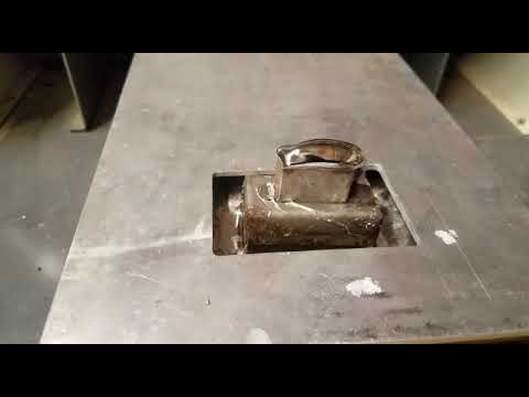
I have a HAKKO-485 that I acquired a few years ago that I use for soldering as well as de-soldering. If you remove the top plate and the raised well, a PCB will float on top of the solder like a boat because the solder is so much denser than the PCB board. Just make sure you have features on the PCB that you can grab it with, such as mounting holes etc.
HAKKO-485 - video
When my business partner and I were doing dip soldering many years ago, we used Multicore X32-10M flux. It came in a rather large container, from which we poured a little into a hand-pressurized spray dispenser. The spray was very fine.
We made tongs out of bent aluminum sheet metal to hold the boards by the edges. Aluminum is important, since it won't plate out in the solder bath. We first clamped the loaded boards with the tongs and, holding the boards horizontally so the parts didn't shift or fall out, sprayed the flux up from the bottom before setting the boards into the molten solder.
The flux would sizzle and pop, and the we would withdraw the boards and, when cool, trim the leads on the bottom. Then we would have to inspect each one for solder bridges, which were very rare.
I don't remember the actual formula for the solder, but I'm guessing it was 63% Pb, 37% Sn.
I'm not sure about the economics of doing it this way any more. It falls between hand soldering and paying an assembly house to do the work for you. If you're looking at largish quantities, l recommend laying out as much of the board as possible with SMD parts, and let someone else do the assembly. Frankly, doing it yourself is probably not worth the hassle.
Hope this helps.
-Phil
Thanks guys!
Phil, the tip on using Al for the tongs is really good to know. I thought I would have to fabricate something, but was hoping someone could point me to a jig on Amazon. Custom jig it is. I also have a 3D printer a friend gave me, that I don't know how to use, but I think I could repurpose the parts to automate this. That might be fun.
The current project is very low volume (20 boards) and no demand for them") It's hobby work and a learning experience for me. I think I can hand populate, dip and clean the boards in 30 minutes each with this method vs 2.5 hours each to hand solder. (There are many, many, fuse holders and connectors) I suspect the results will be better too. Looks like I can get all the tools and materials needed for about $300. That's worth it to me.
It's hobby work and a learning experience for me. I think I can hand populate, dip and clean the boards in 30 minutes each with this method vs 2.5 hours each to hand solder. (There are many, many, fuse holders and connectors) I suspect the results will be better too. Looks like I can get all the tools and materials needed for about $300. That's worth it to me.
I am going to do a SMD version of this, eventually. I can't imagine how much it will cost to have someone assemble boards for me. Sounds expensive.
I use this large dip solder bath
Not very expensive, made in Germany.
The depth is only about 15mm, so no need to purchase large amount of solder pellets.
(Sorry, can't remember the name or type, but will take a look if you are interested)
If you're soldering radial or axial passives and don't want to clip the leads twice, shallow depth will be an issue.
-Phil
Correct, depth is an issue with this thing, if you want to saw of the leads afterwards..
I prepare the component leads first, put them on the PCB panel, then solder and done.
I don't like the finish of that circular saw blade, cutting the leads, and there will be exposed copper.
I mostely use the dip solder for THT connectors with no need for cutting leads. The rest is mostely SMD components. I found it easy to mask bottom side soldered SMD with capton tape and then dip PCB to solder THT parts. Works fast and very easy
The process is the same
Some Lead-free aloy need a little higher temperature.
Most of my components have arrived. I am waiting on 5lbs of solder from Texas to arrive. Not sure if that will be enough, though.
I added a fine mist sprayer on the repackaged Kester 959T I purchased. I hope that is an appropriate flux solution.
nice,
Mike
Nice..
I also just use a mist sprayer (but larger one for misting flowers).
I use liquid flux normally used in a foam fluxer machine.
It needs two coats with baking after each coat.
I use a cheap flat bed bread toaster to bake the circuit board (raised 10cm above the toaster).
That works very well for my type of flux.
I forgot about the flux baking. We used an electric pancake griddle for that.
-Phil
That same griddle with a 1/4 inch layer of DOT 5 brake fluid works wonderfully for the bulk removal of DIP and TH components.
I have seen videos of people just hovering the board above the solder pot to bake the flux. It that acceptable or do I have a trip to the thrift store in my future?
I appreciate all of the comments! Thank you all!
That might work, but a black griddle surface is a more efficient heat radiator than shiny molten solder.
Speaking of shiny, you will want to rake the slag away from the solder surface just prior to dipping each board. IIRC, we used a piece of cardboard for that.
-Phil
Phil,
They used Tongue Depressors to wipe the slag off the top of the solder pot before tinning wires when I worked in catheter production.
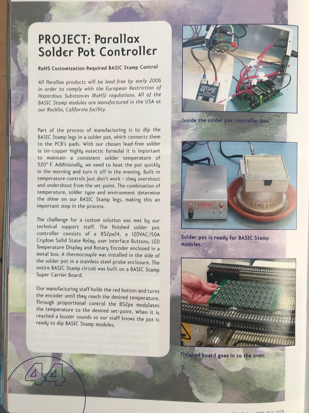
Historical note, from Parallax, their 2006 catalog…
So, I did the first board this evening and I learned a few things.
1) I definitely need something like a hotplate to "pre heat" the board. The board is just too big to hover over the solder pot to heat.") Yep, need to do that.
Yep, need to do that.
2) Even though I covered the vias I wanted to protect with thermal masking tape, I didn't cover my standoff holes that are plated. They are no longer holes
3) My board warps when I dip it. This caused uneven component placement, and required me to redip with a focus on each end. Don't know why this is happening. Any thoughts would be appreciated.
4) The solder looked dull after I was done. I wasn't expecting that.
5) I need some way to clean the boards after dipping, as the flux (or something) appears to leave a residue.
6) I guess it will take some practice to get the timing right.
I had a few rework items, but the board worked first try.
As for "3)", IMHO the difference in copper metal distribution/quantity between the top and bottom layers tends to produce the same effect of a bimetallic sheet, where the "side" that has the higher expansion coefficient will force the sheet to be "convex" when you look from that side standpoint.
As for "4)", if the dull aspect can't be explainned by a layer of flux residues that can be "scrapped" using some soft tool (aka, very soft plastic blade), then it can be due to a too slow cooling of the solder joints, which would increase their final "grain-size", "blurring" an otherwise bright finish. If there is any chance for the pcbs to absorb some moisture prior to soldering, perhaps some 6-8 hours into a 60-80ºC hot oven can be used to "dry" them a bit, before assembly.
As for "5)", check the recommended procedure with the flux provider; it'll spare you a lot of head aches with unnexpected chemical reactions, and the even nasty residues they can cause.
Outstanding job, anyway!!!
Hope it helps
Henrique
I don't have warping PCB, but my system use at carier-frame, so purhaps thats helping to keep it straight.
My solder surface don't get as doll as your, purhaps you dip it far too long time. Or could be depending on the combination of different aloyes in your solder tin.
(I also use lead free).
Pre heat is a must. Flux must be dry, and depending on flux type you may have to give it two layers, with drying in between.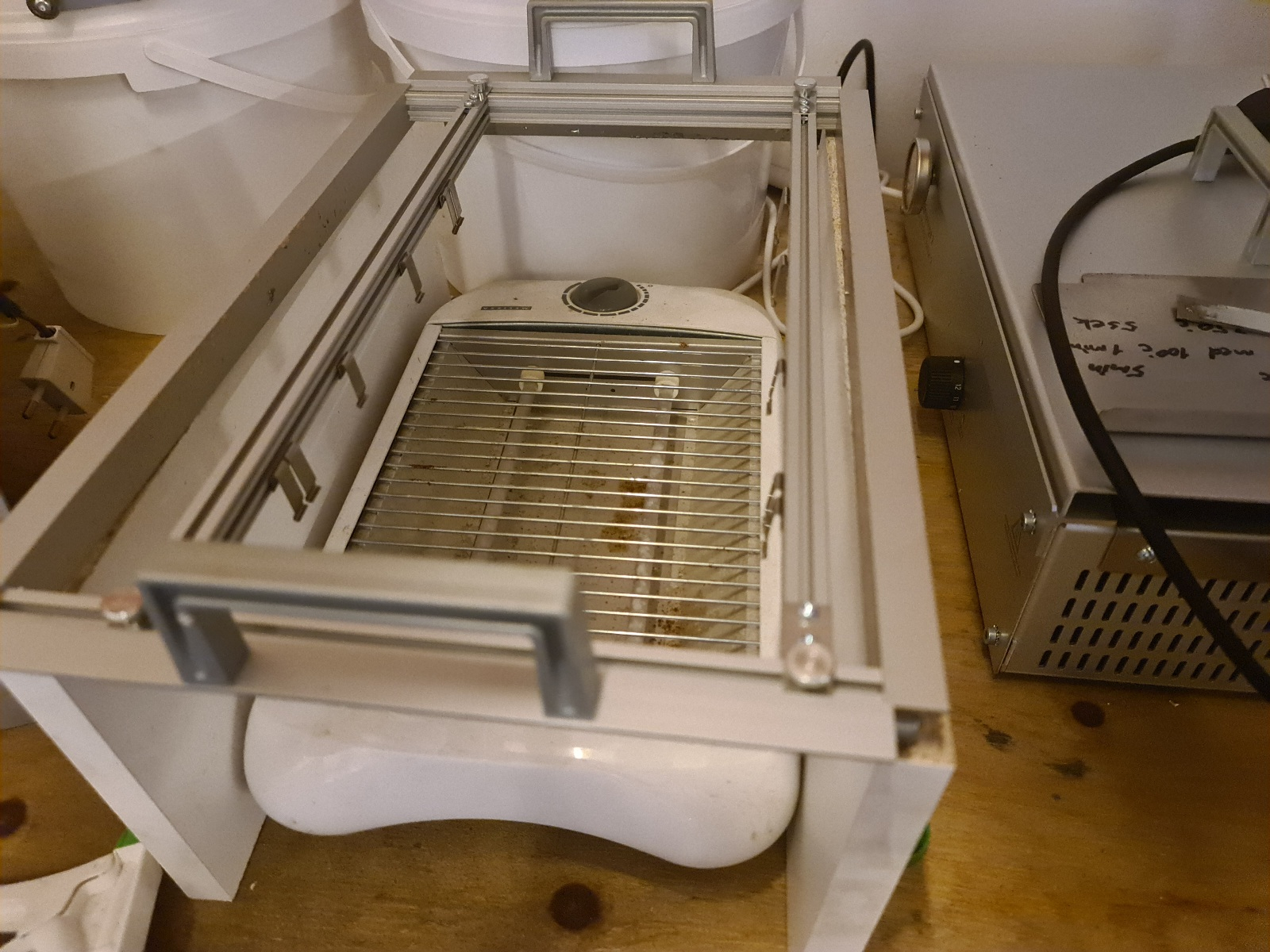
As mentioned earlier i just use a IR bread toaster - see picture.
@MAElektronik what is that jig you have there to hold the pcb? What is it called? That looks perfect!!
It is an accessorie for my solder bath machine from Gie-Tec.
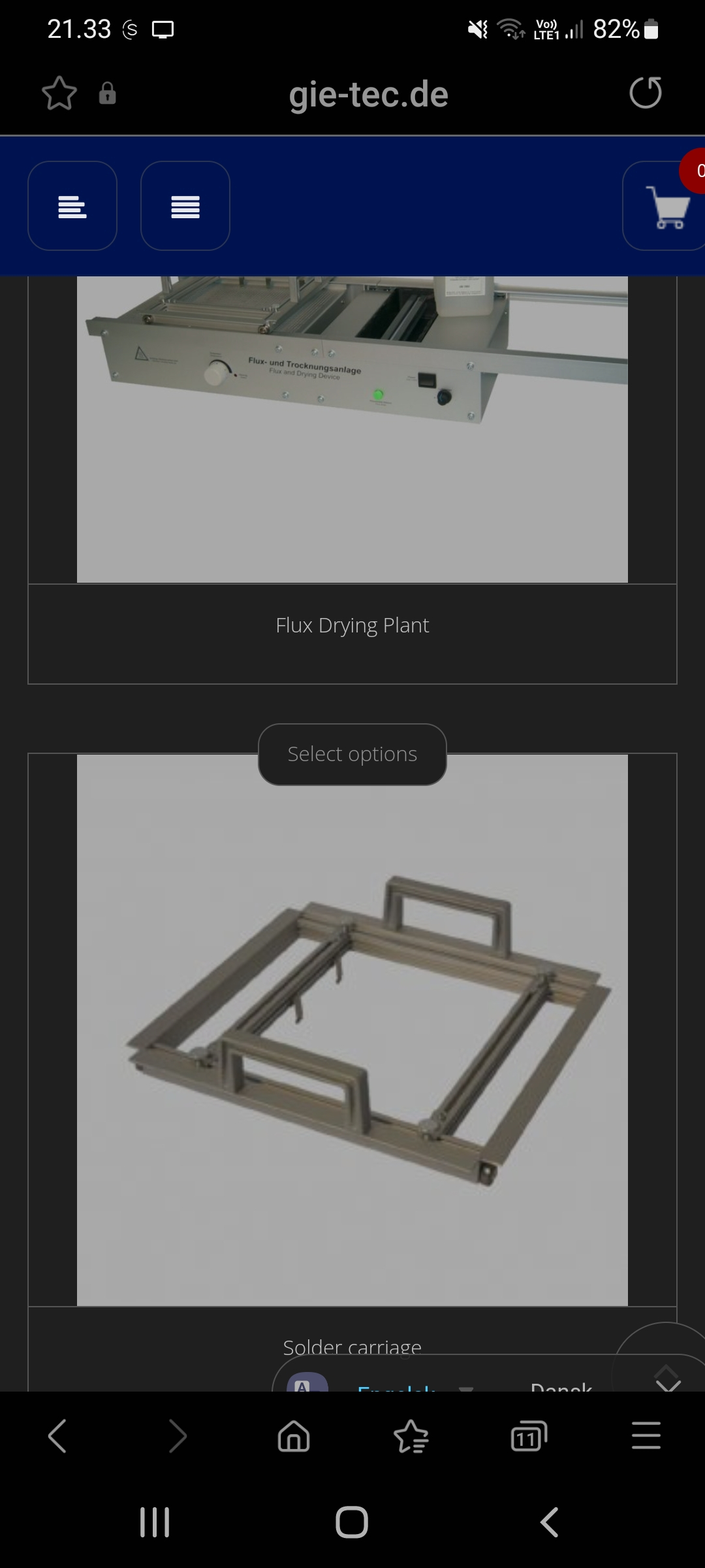
It is actual quite simple made of some aliminium profiles
It has some roller bearings as well, helps to roll into the bath with just the edge of PCB touching at the start.