

Cyber:bot ultrasound sensor 4-PIN

Hi
I gave a Cyber:bot to my kid as a present and he is following the tutorials.
The recommended utrasonic sensor for the cyber:bot in the tutorials comes with 3 pins, sold by Parallax.
I have about 10 similar sensors, but they are the 4 pin version (generic, for Arduino, the ones sold on Amazon).
I know the ones from Parallax gives you the distance on one the same pin used for the trigger, and it is already calculated and free of noise, but I was wondering if I can use the 4-pin generic ones instead.
The ping function from the cyber:bot library gets only one pin as parameter for input and output,, so I probably cannot use that.
What options do I have here?
Maybe using the ping function and connect the pin to the "trigg" pin on the sensor, and read the echo via a different pin on the cyber:bot?
Using these generic sensors will open a lot of possibilities, since I have a few spare ones.
Thanks a lot.
Comments
Look here: https://forums.parallax.com/discussion/comment/1365665/#Comment_1365665
Hi
I found references to people using those 4-pin sensors, but directly on Propeller, with Arduino shields, or on other boards.
I have a bare Arduino and it works just fine.
My issue is that I have the Cyber:bot, which uses a Microbit as main interface via I2C, and there are limitations.
The Cyber:bot I have is Rev A, which doesn't have pins for accessing the Microbit's GPIO directly so Im stuck with what the Cyber:bot python library exposes.
IM using the Microbit V1 with the recommended firmware for Cyber:bot
I use this method below that I found in the cyberbot.py library with some sort of "positive" results:
us = bot(pin).pulse_in
Lets see if I explain this properly.
This particular sensor has 4 pins, two of them are powering it, one pin for trigger and another for echo, therefore Im forced to use two pins for data, on the controller board.
The intention is having one pin generate a 10us trigger signal, which is what that sensor requires in order to start sending the ping, and then use another pin to measure the pulse width that is returned by the sensor.
I have the sensor powered via the onboard 5V and GND from the Cyber:bot shield, the Trigger pin is connected to pin 5 and the Echo pin on pin 10 of the Cyber:bot
When I run the code below I only get "0" on my serial console.
Note the documentation doesnt say that the method .pulse_in requires a parameter, but if I dont add it, I always get on my serial console.
Now, the funny part, if I unplug the sensor's trigger from the Cyber:bot's pin 5, and I put it on an Arduino instead, leaving everything else the same (forcing the Arduino to send the trigger signal to the sensor) then on the Cyber:bot I no longer see just 0 and I see the roundtrip instead, in 'us', just fine. (BTW, the Cyber:bot and Arduino are on common GND)
I tested the same, triggering the sensor with a waveform generator, and the code works, it just doesnt work when the trigger is plugged into the Cyber:bot pin 5.
On all testes I never changed the code, I just move the trigger pin from the Cyber:bot to the Arduino or the waveform generator.
I checked with the oscilloscope, and the Cyber:bot doesnt seem to be sending the signal properly on pin 5 (in my code), no matter what I do, adding sleep or time.sleep_us etc, for example, I cannot make the signal a square wave at 10us, which on Arduino and my generator I can do easily.
No matter what I do, I cannot go LOW for less than 4.5ms or so.
I tried with multiple variations of the code, if I cannot make it work, I could always use a 555 timer to generate the signal I need for the trigger and leave the pin 5 alone, but I wish my code above would work so i save time and real state on the Cyber:bot's mini breadboard.
Maybe my Cyber:bot is faulty, maybe my code is wrong or all of the above
======================
from cyberbot import *

while True:
    bot(5).pulse_out(10)
    us = bot(10).pulse_in(1)
    print(us)


======================
Thanks a lot
In the thread I mentioned (especially if you follow the link in the post) you see how to convert the 4 pin to a 3 pins just like the parallax's Ping. Maybe that can help you to get it to work?
PS to get the code formatted corectly in your post use [ code] [ /code] around the code (take away the space after the opening bracket)
Heads-up... the code formatting is now achieved using 3 backticks on the line before the code, and 3 more on the line after the code. The forum uses Markdown format these days.I don't believe the older [ code] style will work anymore.
Im new to coding myself, Im trying to help my 11yo kid with this. Not sure what are the "backticks", but I will figure it out I guess.
My kid is homeschooling and we are using the Cyber:bot this as a STEM introduction, but he is already doing too much stuff with it and asking too many questions
The Arduino and the sensors I have were inherited from "another life" but it is not that Im well versed on it.
Hopefully I will be able to make the python code and this 4-pin sensor together so I can teach him and this exercise looks more to him like "anything is possible" instead of "oh, we cannot do that"
Thanks guys.
hahaha,, I think I understand what you meant.. It is for the formatting on this page when pasting code.

so sorry I didnt get it quick enough
Yes!! That's it. And the example of what the three backticks look like are on the 2nd line of that code-block I posted")
I was not able to use the 4-pin sensor directly on the Cyber:bot, by either wiring the Trig and Echo pins together (resistors, etc like some people in this forum have done), or by calling bot().pulse_in() and bot().pulse_out() .
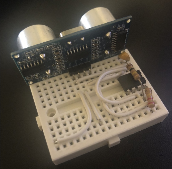
My other choice was to have a 555 timer to drive the trigger pin.
This is my kid learning stuff, and since he knows how the 555 works and has done astable circuits before, I told him to make one for this.
It is not pretty, but it works, the trigger signal comes from pin 3 on the 555, and the echo pin is wired to the cyber:bot , lastly, he is calling bot().pulse_in() on the echo pin, to read the roundtrip.
One last update.
We got tired of having that little protoboard hanging off the bot's chassis.
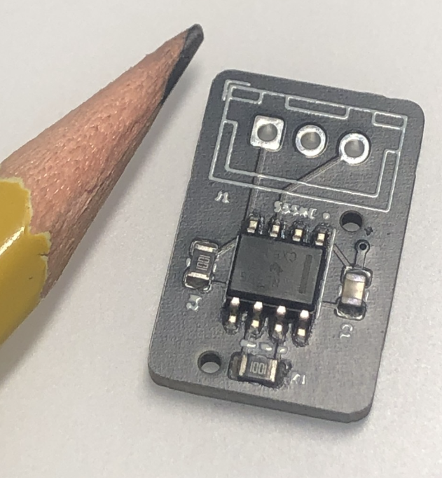
So we took it a step further and made it a PCB
19mmx12mm, fairly small, on purpose, so we could hide it under the chassis.
Since it is powered by 5V, the output of any GPIO from the Cyber:bot is able to turn it On or Off at will, or we can just hardwire it to 5V from anywhere,
Total investment: $15 for 5 pieces
Never made a PCB design before, but I think it is not that bad, and most importantly, it works.
Fabulous. You must be so proud of your young prodigy! That's a super layout and final board to replace the breadboard.
The only thing I might suggest for next time, is that it's best not to have the via beside C1 on such a long trace. Try to position the via right next to the C1 pad. Even on the inside of the pad (under the cap) if it fits.
It won't matter for this circuit, but that's good practice and will matter in many future (and more complex) designs I can imagine you'll be making.
Bravo, and thanks for sharing. Really great job.
Note taken !!
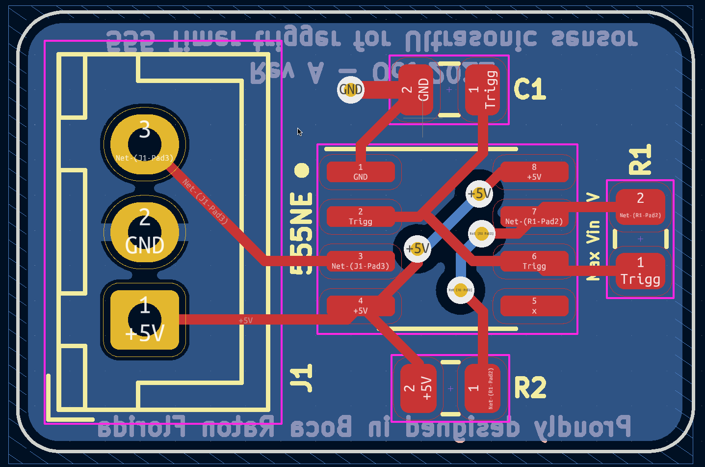
It is a two-layer PCB, the whole bottom is a ground plane, and the via goes straight there.
Here is what I did in KiCAD, Im surprised that it actually works, I though on first try I was going to waste the $
Thanks for the feedback.
Nice! Welcome to KICad. You’re going to have a lot of fun making mischief now that you have your first design built and tested.