

Drive DC motor with DRV88771 driver and P2
 chintan_joshi
Posts: 135
chintan_joshi
Posts: 135
Hello,
I am trying to drive DC motor with DRV8871 driver(https://www.adafruit.com/product/3190) and P2 controller.
I have created below code for DC motor.
Pin connections:
P2 : DRV8871
Pin 32: IN2
Pin 33: IN1
Pin 34: VM
GND: GND
DRV 8871 POWER pins are connected to 12 v DC supply and P2 is supplied with Standard P2 power adapter.
But when i LOAD code and switch on 12v supply then not able to see any output.
Also whole 32 to 39 pins are not working. So am i making any mistake here?
i have used same circuit configuration with arduino and DRV8871 and there i can able to see motor movement and no issue observed on Arduino pins.
// Basic sketch for trying out the Adafruit DRV8871 Breakout
define MOTOR_IN1 9
define MOTOR_IN2 10
void setup() {
Serial.begin(9600);Serial.println("DRV8871 test");
pinMode(MOTOR_IN1, OUTPUT);
pinMode(MOTOR_IN2, OUTPUT);
pinMode(11, OUTPUT);
}void loop() {
digitalWrite(11, HIGH);
// ramp up forward
digitalWrite(MOTOR_IN1, LOW);
for (int i=0; i<255; i++) {
analogWrite(MOTOR_IN2, i);
delay(10);
}// forward full speed for one second
delay(1000);
// ramp down forward
for (int i=255; i>=0; i--) {
analogWrite(MOTOR_IN2, i);
delay(10);
}
digitalWrite(11, LOW);
digitalWrite(11, HIGH);
delay(1000);// ramp up backward
digitalWrite(MOTOR_IN2, LOW);
for (int i=0; i<255; i++) {
analogWrite(MOTOR_IN1, i);
delay(10);
}// backward full speed for one second
delay(1000);// ramp down backward
for (int i=255; i>=0; i--) {
analogWrite(MOTOR_IN1, i);
delay(10);
}delay(5000);
}
Comments
In my case, VM is common to the motor power (is it "Volts-Motor"?) and I was using 24v on the Power terminals....Smoked my MCU.
Apparently, VM is for powering low-power motors instead of using the main power terminals.
I made the mistake of assuming that it was logic-level on one side of the board and power on the other. Not true.
Craig
Edit: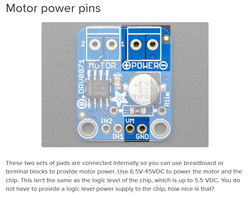
Sure enough....
Hello @Mickster , Thank you for the reply. Yes its totally confusing. And now i lost my 8 pins of P2 board. and you saved my remaining 56 P2 pins.
Surprisingly Arduino Leonardo board works with same configuration.
And also have one doubt, don't we need to connect GND of P2 to DRV8871 driver? Because in current scenario Motor supply is different and P2 supply is different.
I checked with suggested solution and now i can able to run dc motor in forward and reverse direction without any harm to P2 pins. Thank you again.
Great news
Losing the 8 pins hurts though.
I have 13 or 14 Picos and I use these to test unfamiliar hardware before connecting to the P2.
Craig
Yes right, Will follow same. Thank you.
Hi @chintan_joshi
Can you please tell us what P2 board you're using in you experiments?
I'm asking it because there is at least a small chance you didn't burnt/lost the whole group of eight pins [39:32]; it'll depend on the pcb you're using, and the way Vio (3.3 V) is/was being fed to them all.
Internally, at the silicon pad ring, are there two independent branches; Vio[35:32] connected to package pin 55, and Vio[39:36] connected to package pin 61. Both P2 Eval and Edge boards have a single voltage regulator that simultaneously feeds power to both branches, thus, in case the regulator fails/fuses (or, less likelly but still possible, one or both associated 4.7 uF x 6.3 V capacitors did shorted due to overvoltage), there'll be not any 3.3 V power at those Vio, at all.
So, checking if Vio[39:32] is still present, and at its expected 3.3 V level is a good way to determine if something went wrong at those nodes.
Even if there is some lower residual voltage level, there's still a chance that only four pins are realy bad, shorted to GND, and the regulator could have "survived", but limiting its output due to being drainned into a continuous overcurrent situation by one of the branches.
Just don't forget to check the associated capacitors for shorts too.
Hope it helps
Henrique
Hello @Yanomani ,
I am using P2 Edge Module with P2 Edge Module breadboard. i purchased (https://www.parallax.com/product/propeller-2-developer-starter-bundle/) .
I have checked Pin 36 to 39 by making it output and set its value to HIGH but not able to see 3.3 v on pins.
So now is time for you to get the proper schematics of your P2 Edge Module and P2 Edge Module Breadboard correct version from both product's pages, and conduct a little research, in order to verify if there any outstanding short-circuited components at the corresponding nodes.
Chances are still good you can find some outstanding "blown/fused" component outside of P2 package, and "salvage" four good pins, at least.
It'll be a real pity If nothing can be recovered, at all...
Also wondering if that particular pin on the Leonardo really did survive? Different architecture, that one pin might be dead(?)
Craig
Those of us who've been around the block a few times have certainly done that -- which is why I am always adamant with newcomers to download and consult the data sheet for any part they're going to use.
If you're just doing simple motor control with two pins, it may be more efficient to translate the PWM code directly into C. I'm not an experienced C programmer, but even I was able to make it work and it ran the first time.
#include <stdio.h>
#include <propeller.h>

#define  MTR_PWM 40
#define  MTR_DIR 41

#define  PWM_HZ  20_000


void setup();
void setSpeed(int spd);


void main()
{
    setup();

    setSpeed(33);

    while (1) {
    }
}


void setup()
{
    uint32_t mode = P_OE | P_PWM_SAWTOOTH;                  // set pwm mode
    uint32_t xval = (_clkfreq / PWM_HZ) / 100;              // set unit timing

    if (xval == 0) xval = 1;                                // constrain ticks
    if (xval > $FFFF) xval = $FFFF;
    xval |= 100 << 16;                                      // set units for 100%

    _pinstart(MTR_PWM, mode, xval, 0);                      // make pin pwm output
    _pinl(MTR_DIR);                                         // initialize direction control
}


void setSpeed(int spd)
{
    if (spd > 0) {
        if (spd > 100) spd = 100;
        _wypin(MTR_PWM, spd);
        _pinl(MTR_DIR);
    }
    else if (spd < 0) {
        if (spd < -100) spd = -100;
        _wypin(MTR_PWM, 100+spd);
        _pinh(MTR_DIR);
    }
    else {
        _wypin(MTR_PWM, 0);
        _pinl(MTR_DIR);
    }
}
Output with speed set to 33%.
I did confirm that setting the speed to a negative value inverts the direction control pin and the PWM duty cycle.
Hi Jon.
Read the data sheet but the modules were an impulse Aliexpress purchase. They showed up and I couldn't wait to test
I always use a (disposable) RPi Pico in these circumstances. Blow one up and I just go with one less beer at the pub and I'm even
Craig
Been there. Done that. Especially since orders from Aliexpress show up weeks after one has ordered and long forgotten about the purchase.
Never go with one less beer!
In actuality, it's a slightly less vigorous protest at last call, resulting in only 2 after-hours pints instead of 3
Craig