

P2 Edge Connections
 ke4pjw
Posts: 1,334
ke4pjw
Posts: 1,334
in Propeller 2
Is this an accurate representation of the pinout for the P2 Edge?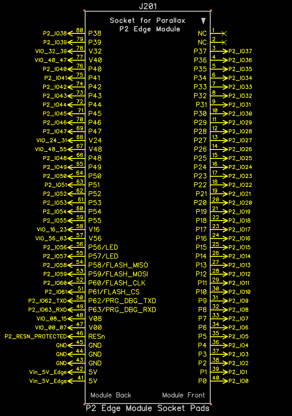
Comments
Currently, there are three versions of the "Vanilla" P2 Edge (without 32MB Psram)!
Due to that diversity, the Download section at product's page can be your best source of information; all three product guides and schematics are there, as pdf files.
https://parallax.com/package/p2-edge-module-product-guide/
https://parallax.com/package/p2-edge-module-schematics/
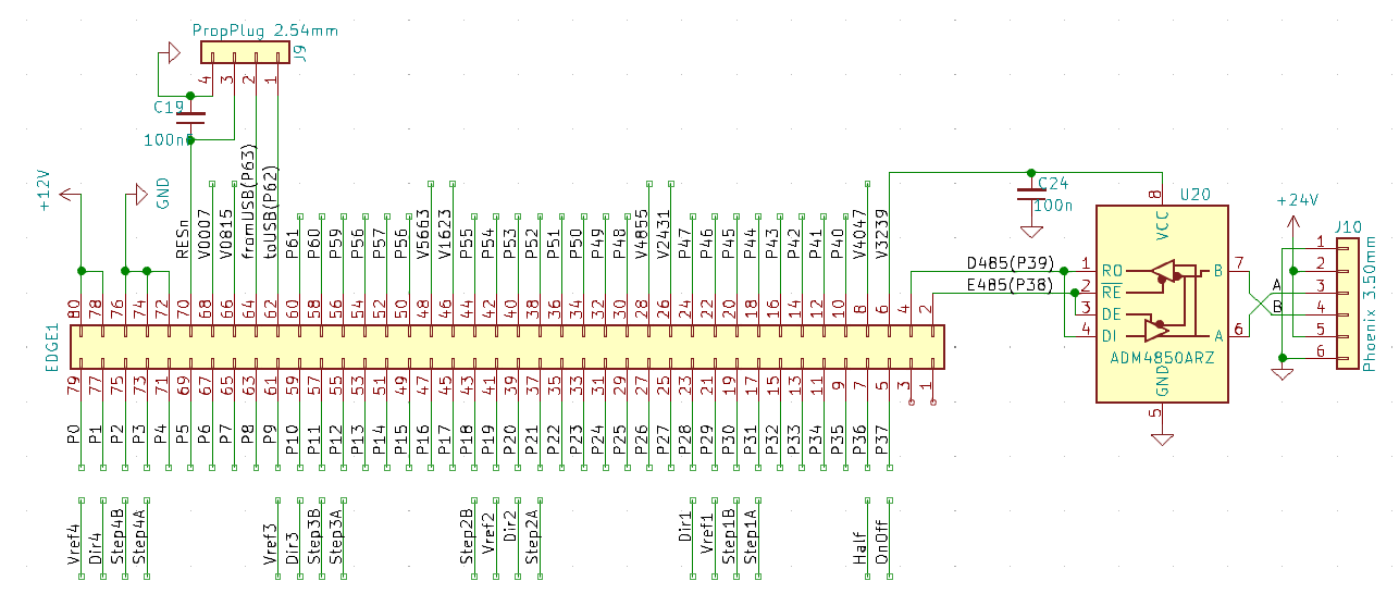
Being an edge connector there's more than one pin config for them. Here's a schematic I started on a while back but never finish. Which one is best is dependent on the socket's footprint library part.
Schematic states Pin 3 on the connector maps to P37 on the Prop2. I assume that is Pin 3 on the through hole connector side of the board. It is unclear. It looks like what I posted above, which is what I got from Diptrace.
The Product Guide has no mappings. It makes it appear that Pin 0 (V00) maps to P0 on the Prop2. It is more unclear.
Just trying to make sure I am not doing it wrong.
The pin ordering and side labelling looks good to me. Just have to be careful the socket footprint matches is all.
I believe you'll find better information about the edge connector pinout at the P2 Edge Mini Breakout Board product page.
At least there is a single schematic and product guide, whith bottom and top views fo the connector pin-pattern.
https://parallax.com/package/p2-edge-mini-breakout-board-product-guide/
https://parallax.com/package/p2-edge-mini-breakout-board-schematic/
Hi @ke4pjw
I did an slight edition (in white) over one of the images, present at the Mini Breakout product manual, showing where P2_IO37 is conected.
Hope it helps
P.S. Just found a post from @VonSzarvas (dated 2021-12-22) showing that region of the "P2 Edge Breadboard #64020"
https://forums.parallax.com/discussion/comment/1532710/#Comment_1532710
There's a third pin order too. The X-Y grid order where the numbering runs down in columns. Some use letters for the columns so that the numbers are then repeated in each column.
It seems I was knocking at the wrong door...
https://parallax.com/package/p2-edge-80-pin-adapter-kit-header-and-socket-pinouts/
https://parallax.com/package/p2-edge-80-pin-adapter-kit-product-guide/?wpdmdl=6801&refresh=62d4f04bbfdbc1658122315
Ok... I looked at that pictures several times and I'm sure I'm missing something... but... aren't the 5v labels located where it appears to be connected to the ground copper pour? And the 3 GND pins seems not connected to each other as I would expect... on the other side, the NC pins appears correct, so... what I'm missing?
Edit: of course, two minutes after posting... missed reading the whole document... the copper pour is the +5v power rail connected to the pads!
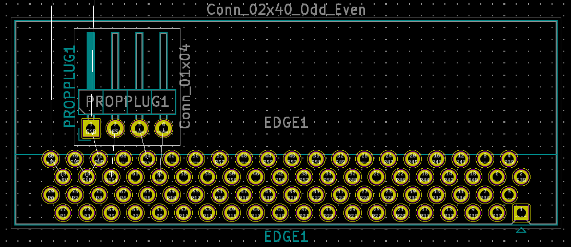
Thanks for everyone taking a look. Let me explain my circumstance a little better. I am doing a board layout that will use the P2 Edge. Here is the product I purchased from Parallax to facilitate that. https://www.parallax.com/product/80-pin-edge-connector-socket-straight-through-hole/
I converted the Diptrace files available for that product to the layout software that I use, ExpressPCB Plus. Here is what my layout looks like.
Pin 40 should be P0 on the Prop2.
Pin 3 should be P37
Does that seem correct?
I cannot reconcile the differences between mine and the one @Yanomani posted of the Mini-Breakout board. The only way that works for my board is if I flipped the layout.
I think the diptrace files are wrong in the bundle. Diptrace shows the same as my converted file.
You're welcome, and the answer is a sound Yeah!
Just remember to check what would happen to your board/design in case P2 EC card gets incidentally reversed at the connector.
That would bridge P37, P36 and P35 together (pins 3, 4 and 5 from your connector land pattern count); P2 EC can deal with that condition very nicelly, so it wouldn't get harmmed in any way.
The reversal would also bridge pins 1 and 2 of your board connector; this fact can be used with some advantege in your design, mainly if it has a "Reset" switch, meant to bring the rest of the logic to a known state. Again, P2 EC card would not sense that situation, because it would not get any power feed in such a condition.
Wait wait wait. That works. My brain is hurting.
To me, parallax (sic) and perspective where ever "mind concepts"; I mostly can only see things in 2D; 3D where ever a "luxury", kind of a "reality-based", forever going dream...
I don't know if this will help, but this is from a JonyJib project that John laid out and I coded. It works well, so I'm assuming what he's marked is correct.
Thread is perfect timing...been through the steps above (breakout board) and yeah the 5v that I initially believed to be the ground plane
Gonna check for the 50,000th time and get this board (400mm X 150mm) out for manufacturer.
Craig
Here's the footprint I'm working with. Pin 1 is notably different to what Jon's one is. That's a good example of things to look out for. The schematic symbol needs to match the used footprint. There's no one-config-fits-all here.
PS: Mine is a right-angle socket of course. And I've chosen to have the Edge Card face up on the carrier. If I was to have the Edge Card face down I'd rotate all the pin mappings 180 degrees - So then 12 Volt supply would be on Pin 1 of the edge socket.
EDIT: Swapped face up/down.