@evanh said:
I don't run the DRC. It complains too much about the outlines overlapping. I'm happy with interactive copper clearances for keeping me on the right track. ... I see the DRC is reporting one error where C8 overlaps the connector. I know that has enough room in reality.
Interestingly, the unconnected VSS/VDD nets aren't reported in the DRC report. The two fill zones are spec'd for VSS and VDD so sensibly they are accounted for, I presume. But there is a bunch of data tracks reported as unconnected at various vias ... EDIT: Nothing wrong with them! All tracks are connected to those vias.
EDIT2: Ah, lots of VSS/VDD are reported when the fillszones are not filled in, ie: when CTRL-B'd
EDIT3: I did change the board setup part way through, from a 2-layer to a 4-layer. I got my four layers, and no odd-ball behaviour resulted. Shrug, dunno why it's got warnings at some of the vias.
By solely refering to the layouts you've published (right now, I'm just downloading Kicad's last version; it'll take many "eons" on this crappy wi-fi I'm using...) I can't be totally sure, so need to ask it to you, anyway (if my eyes are not fooling me, once more): are there two differing VIO's (comming from two 12-pin interface connectors) shorted togheter at a common 3.3V plane?
Such a VIO short would be bad. I'm also wondering if you have a trace connecting each of the TH pins to the SMT pads on that connector... if not, could be a cause of many DRC errors.
Since Hyper_Things/OPI_Psrams have separate VDD and VDDQ connections, in principle, it's ok to designate the VIO that pertains to the same connector from where DQ[7:0]-lanes come from as VDDQ (responsible for power-feeding the whole device's I/O pin-block (CE#, CLKs, DQS/DM (RWDS fro Hypers), and DQ[7:0]), and the other VIO as VDD (responsible for delivering power to the rest of each device's internal circuitry, including the (heavy-consuming) main memory array).
The chip-enables and clock-lines are input-only (from each Ram/Flash-device's standpoint), so a very-low-value resistor, inserted in series with each of those signals (near their entry point, closer to the connector) should be enough to mitigate any voltage-difference-induced waveform distortion; as for the DQS/DMs (and Hyper-RWDSs), they are bidirectional, and most of the time they'll tend to switch at the same rate as DQ[7:0].
The only reliefing-factor is that all those I/O-capable signals (DQs, DQS/DMs (and RWDSs)) don't really change direction too fast (at least not as fast as device's operational clock rate), thus there shouldn't be any low-series_impedance-related conflicts between the differing VIO's that would be driving them; perhaps a single very-low-value resistor, inserted in series between the connection of signal's entry-point and the lane that connects all devices togheter can be proved as good enough.
It's important to note that the number of decoupling capacitors would need to be doubled (at least) and it could be wise to leave provisions for two extra ~1 to 4.7uF capacitors, closer to those VIO entry points (near the two connectors).
P.S. Signal integrity concerns wiselly demands that no high-switching-rate lanes could be routed as transposing any power-related plane-splittings.
When this rule must be forcefully violated, there are extra (and specific) ways of mitigating the consequent impedance discontinuities (aka: suitable high-frequency capacitors, closely surounding the signal lanes, connecting the two "halves" of split-planes, near the transposition (think in some kind of bridge parapet walls))
Like Rayman, I figured it was better to have them both together than only use one.
I'm also wondering if you have a trace connecting each of the TH pins to the SMT pads on that connector... if not, could be a cause of many DRC errors.
Nope, kept well clear of those header pin holes. Had to spend extra time being creative with those routes compared the regular header sockets.
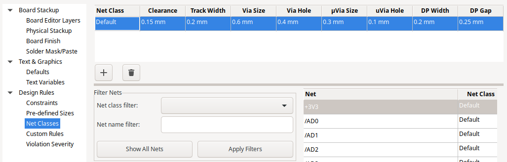
I did have to shrink the default clearances in Kicad to work with those BGA chips though. The biggest change was the via ring size down to 0.6 mm.
@Yanomani said:
Since Hyper_Things/OPI_Psrams have separate VDD and VDDQ connections, in principle, it's ok to designate the VIO that pertains to the same connector from where DQ[7:0]-lanes come from as VDDQ (responsible for power-feeding the whole device's I/O pin-block (CE#, CLKs, DQS/DM (RWDS fro Hypers), and DQ[7:0]), and the other VIO as VDD (responsible for delivering power to the rest of each device's internal circuitry, including the (heavy-consuming) main memory array).
Maybe. I'm not rushing to it.
The only reliefing-factor is that all those I/O-capable signals (DQs, DQS/DMs (and RWDSs)) don't really change direction too fast (at least not as fast as device's operational clock rate), thus there shouldn't be any low-series_impedance-related conflicts between the differing VIO's that would be driving them; perhaps a single very-low-value resistor, inserted in series between the connection of signal's entry-point and the lane that connects all devices togheter can be proved as good enough.
Software could conflict in this way but unlikely to be damaging. We want the speed - Fix the bugs.
I am thinking about reinstating the 74HC138 I had earlier. Those things are built just for doing low-active chip selects on a common bus. I threw it away because I didn't have another purpose for all the spare I/O so they all became chip selects.
@evanh said:
I am thinking about reinstating the 74HC138 I had earlier. Those things are built just for doing low-active chip selects on a common bus. I threw it away because I didn't have another purpose for all the spare I/O so they all became chip selects.
Did you consider the extra cycles it could take in SW to setup the address bits on each access to generate a chip select with a 74HC138 vs driving a single CE pin high/low? In my case I have the CE pin number already known from my per bank information lookup, hence it only takes one extra instruction to drive it either high or low with drvh/drvl on that pin, easy. A 138 decoder would need the 3(?) address pins correctly setup from the bank/address bits. You'd likely need to SHIFT, OR or AND a bit mask to one of the OUTx registers and you'd need to know which OUTA/B register to use as well. Could be slower...
@rogloh said:
... You'd likely need to SHIFT, OR or AND a bit mask to one of the OUTx registers and you'd need to know which OUTA/B register to use as well. Could be slower...
Sorted. Appropriate choice of address pins to align to a whole nibble helps greatly. SETNIB can operate directly on OUTx registers.
The nibble is dynamic depending on bank being addressed, it is almost extra address lines. Selecting OUTA/OUTB to suit where the accessory board is plugged in I guess will need patching at init.
EDIT: "almost extra address lines" ... On that note, in my experimenting I've got the RAM chips selecting using Y1..Y6, with Y0 and Y7 unused. Maybe I should add pull-ups on the nibble pins and shift the RAMs onto Y0..Y5 instead.
Nope, kept well clear of those header pin holes. Had to spend extra time being creative with those routes compared the regular header sockets.
I meant that the DRC check might consider the 12 TH's as unconnected and throw an error. You could route to either the hole or the smt pad (assuming the TH's are plated), but that's another thing. I was just thinking of reasons that the DRC might bug you, and that it could be upset if it expects all the smt AND TH pads to be connected to the net, whereas you may not have connected the TH's in the layout. Sure, that all depends on the part creation and schematic too... just hunting for gotchas!
One other reason to ensure the SMT and TH pads are physically connected on the layout- in case you run out of the nifty low-profile connectors and decide to stick some TH sockets instead. Then you will need those TH pads joined to the signal traces.
-This all might be moot. Your part may have the pads joined at the hip anyway ! Not used KiCAD, so I don't actually know how/when it would throw DRC errors on such a part.
Incidentally, if your aim was to source more current, then would 500mA be sufficient ? One of those LDO's will provide that.
300mA is the nominal output current, yet the NCP114's are capable of providing up to 600mA (in theory) current limit. In testing I noted that 500mA was a reliable expectation without significant voltage drop across a range of temps.
@VonSzarvas said:
-This all might be moot. Your part may have the pads joined at the hip anyway ! Not used KiCAD, so I don't actually know how/when it would throw DRC errors on such a part.
They are pads but aren't assigned a signal. They're type "NPTH, Mechanical". Which I take to mean just a drill hole.
DRC only has a single error for C8 overlapping of J2. There is a hundred warnings for touching silkscreens, but also a few for unconnected vias too.
@VonSzarvas got to the first paragraph:
Even though the two LDOs may use the same rated output voltage, in actuality the output voltages vary between manufacturers.
But I’d guess you have not just same manufacturer but same batch in most cases, right? (Ooops @evanh already said this)
Also, looks like worst case is that all current supplied by just one ldo. I think that’d be ok for this particular application.
But I do like the idea of ballast resistors when high power is needed.
Yeah, the issue is that even from the same batch/mfg, VOUT will vary by some tolerance. However small, whatever the variance amount (which will increase with load), it will mean one LDO carries the weight. If you keep below 500mA total load then it may not matter. Generally you'd want to add the shunt resistors though, which will introduce some voltage drop and additional power dissipation, so not an ideal solution. Better to use one larger LDO on the addon if you need more current and a common rail, or just split the voltage busses according to which LDO is related to which set of IOs.
Edit: Then again- it's a prototype, so go wild ! Over obsessing delays play !
Henrique's idea of one for VDD and one for VDDQ is a decent approach but there isn't a spare layer for distributing split rails so it would need hand layout to split a layer. Something I don't know how to quickly and not much interested in the tediousness of every chip.
@Yanomani said:
... it'll take many "eons" on this crappy wi-fi I'm using...
I'm guessing wired is not an option.
No, unfortunatelly it's not.
The only-lonelly wires here are the power cords and some mundane cables, connecting things like the VGA monitor, and sure, some USB interconnections too (though I'm still lacking any 3.0 Hub)...
Coax and fiber are available at the neighbourhood (at a premium), but my 4G-wi-fi contraption is "gratis" anyway, so the speed-penalty happens to be my solelly option...
@evanh said:
4G is cellular. How is that not billed to you?
There's this friend-of-mine who runs a very large business, where 4G and wi-fi are a must have; their success depends on it.
So a large number of ever-ready spare equipment is essential, just in case something went haywire (accidents, equipment crashes, whatever). As technology evolves, old stuff is left behind, replaced by new (and feature-enhanced) stuff. I just need the basics, for everyday use.
He uses to call whenever some consulting/support is needed, and I'm happy to provide as much help as possible.
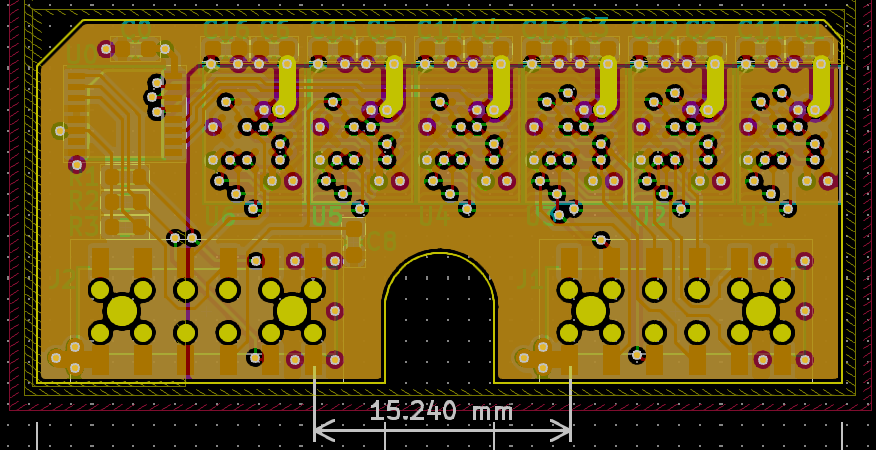
Decided to have a play with splitting a layer for power. Learning the tools. It worked out a breeze using zone priorities. The biggest hassle was the doubling up of capacitors and vias for them, shifting labels. (And some bug with VDD changing to VCC after every edit of the schematic. )
And snap of schematic:
EDIT: Updated with revised pins for bank select nibble and SCLK.
Well 16MB is a better match for my bank size in my driver if you need contiguous banks. 8MB will incur some foldover currently, but for single bank setups this is not typically an issue.
Doesn't seem like you save any IO pins with the 138 decoder in the 6 device setup, this board still burns two 8 bit expansion ports and has 3 IO pins left.
@rogloh said:
Doesn't seem like you save any IO pins with the 138 decoder in the 6 device setup, this board still burns two 8 bit expansion ports and has 3 IO pins left.
Yep, I liked the nibble approach above. So two spare I/O for something else. Could make the board larger.
EDIT: I suppose DQS could be moved to high bit of the nibble. It'll default as an input during bank select. That'll free up the third I/O pin. EDIT2: Maybe SCLK would be better choice. Its OUT is overridden by the clock smartpin.
EDIT3: Done. The post (#116) with files attached is updated.


Comments
By solely refering to the layouts you've published (right now, I'm just downloading Kicad's last version; it'll take many "eons" on this crappy wi-fi I'm using...) I can't be totally sure, so need to ask it to you, anyway (if my eyes are not fooling me, once more): are there two differing VIO's (comming from two 12-pin interface connectors) shorted togheter at a common 3.3V plane?
Such a VIO short would be bad. I'm also wondering if you have a trace connecting each of the TH pins to the SMT pads on that connector... if not, could be a cause of many DRC errors.
Is connecting two vio really bad?
I thought about it a while and thought it was better than just using one of them..
Since Hyper_Things/OPI_Psrams have separate VDD and VDDQ connections, in principle, it's ok to designate the VIO that pertains to the same connector from where DQ[7:0]-lanes come from as VDDQ (responsible for power-feeding the whole device's I/O pin-block (CE#, CLKs, DQS/DM (RWDS fro Hypers), and DQ[7:0]), and the other VIO as VDD (responsible for delivering power to the rest of each device's internal circuitry, including the (heavy-consuming) main memory array).
The chip-enables and clock-lines are input-only (from each Ram/Flash-device's standpoint), so a very-low-value resistor, inserted in series with each of those signals (near their entry point, closer to the connector) should be enough to mitigate any voltage-difference-induced waveform distortion; as for the DQS/DMs (and Hyper-RWDSs), they are bidirectional, and most of the time they'll tend to switch at the same rate as DQ[7:0].
The only reliefing-factor is that all those I/O-capable signals (DQs, DQS/DMs (and RWDSs)) don't really change direction too fast (at least not as fast as device's operational clock rate), thus there shouldn't be any low-series_impedance-related conflicts between the differing VIO's that would be driving them; perhaps a single very-low-value resistor, inserted in series between the connection of signal's entry-point and the lane that connects all devices togheter can be proved as good enough.
It's important to note that the number of decoupling capacitors would need to be doubled (at least) and it could be wise to leave provisions for two extra ~1 to 4.7uF capacitors, closer to those VIO entry points (near the two connectors).
P.S. Signal integrity concerns wiselly demands that no high-switching-rate lanes could be routed as transposing any power-related plane-splittings.
When this rule must be forcefully violated, there are extra (and specific) ways of mitigating the consequent impedance discontinuities (aka: suitable high-frequency capacitors, closely surounding the signal lanes, connecting the two "halves" of split-planes, near the transposition (think in some kind of bridge parapet walls))
Like Rayman, I figured it was better to have them both together than only use one.
Nope, kept well clear of those header pin holes. Had to spend extra time being creative with those routes compared the regular header sockets.
I did have to shrink the default clearances in Kicad to work with those BGA chips though. The biggest change was the via ring size down to 0.6 mm.
Maybe. I'm not rushing to it.
Software could conflict in this way but unlikely to be damaging. We want the speed - Fix the bugs.
I am thinking about reinstating the 74HC138 I had earlier. Those things are built just for doing low-active chip selects on a common bus. I threw it away because I didn't have another purpose for all the spare I/O so they all became chip selects.
I'm guessing wired is not an option.
Did you consider the extra cycles it could take in SW to setup the address bits on each access to generate a chip select with a 74HC138 vs driving a single CE pin high/low? In my case I have the CE pin number already known from my per bank information lookup, hence it only takes one extra instruction to drive it either high or low with drvh/drvl on that pin, easy. A 138 decoder would need the 3(?) address pins correctly setup from the bank/address bits. You'd likely need to SHIFT, OR or AND a bit mask to one of the OUTx registers and you'd need to know which OUTA/B register to use as well. Could be slower...
Sorted. Appropriate choice of address pins to align to a whole nibble helps greatly. SETNIB can operate directly on OUTx registers.
Will you need to patch the executable with the correct nibble and correct OUT register?
The nibble is dynamic depending on bank being addressed, it is almost extra address lines. Selecting OUTA/OUTB to suit where the accessory board is plugged in I guess will need patching at init.
EDIT: "almost extra address lines" ... On that note, in my experimenting I've got the RAM chips selecting using Y1..Y6, with Y0 and Y7 unused. Maybe I should add pull-ups on the nibble pins and shift the RAMs onto Y0..Y5 instead.
Oh, the nibble number is immediate addressing ... ALTSN + SETNIB might be the way - so one extra instruction ...
EDIT: Yep, that works a treat:
        mov bcdlen, #8
        mov portnum, ##OUTA<<3
.loop1
        mov banknum, #5
.loop2
        mov outb, #0
        mov outa, #0

        altsn   portnum
        setnib  banknum

        mov pa, outb
        call    #itoh
        mov pb, #","
        call    #putch
        mov pa, outa
        call    #itoh
        call    #putsp
        djnz    banknum, #.loop2

        call    #putnl
        incmod  portnum, ##OUTA<<3+14  wcz
    if_nc   jmp #.loop1
        call    #putnl
gives the following output:
EDIT: Here's a revised code loop that eliminates the double #'s and makes the port number a simple index of OUT nibbles.
mov bcdlen, #8 mov portnum, #14 .loop1 mov banknum, #5 .loop2 mov outb, #0 mov outa, #0 altsn portnum, #OUTA setnib banknum mov pa, outb call #itoh mov pb, #"," call #putch mov pa, outa call #itoh call #putsp djnz banknum, #.loop2 call #putnl djnf portnum, #.loop1 call #putnlYou really should have some isolation because the VOUTs will vary- at least balancing resistors. I think our friend Yanomani already covered reasons, and this app-note also explains:
https://fscdn.rohm.com/en/products/databook/applinote/ic/power/linear_regulator/parallel_ldo_an-e.pdf
I meant that the DRC check might consider the 12 TH's as unconnected and throw an error. You could route to either the hole or the smt pad (assuming the TH's are plated), but that's another thing. I was just thinking of reasons that the DRC might bug you, and that it could be upset if it expects all the smt AND TH pads to be connected to the net, whereas you may not have connected the TH's in the layout. Sure, that all depends on the part creation and schematic too... just hunting for gotchas!
One other reason to ensure the SMT and TH pads are physically connected on the layout- in case you run out of the nifty low-profile connectors and decide to stick some TH sockets instead. Then you will need those TH pads joined to the signal traces.
-This all might be moot. Your part may have the pads joined at the hip anyway ! Not used KiCAD, so I don't actually know how/when it would throw DRC errors on such a part.
Incidentally, if your aim was to source more current, then would 500mA be sufficient ? One of those LDO's will provide that.
300mA is the nominal output current, yet the NCP114's are capable of providing up to 600mA (in theory) current limit. In testing I noted that 500mA was a reliable expectation without significant voltage drop across a range of temps.
They are pads but aren't assigned a signal. They're type "NPTH, Mechanical". Which I take to mean just a drill hole.
DRC only has a single error for C8 overlapping of J2. There is a hundred warnings for touching silkscreens, but also a few for unconnected vias too.
Not too bad.
My feeling is, since the LDOs are not only from the same manufacturer but also the same batch, they'll be well matched. Within 0.5% of each other.
@VonSzarvas got to the first paragraph:
Even though the two LDOs may use the same rated output voltage, in actuality the output voltages vary between manufacturers.
But I’d guess you have not just same manufacturer but same batch in most cases, right? (Ooops @evanh already said this)
Also, looks like worst case is that all current supplied by just one ldo. I think that’d be ok for this particular application.
But I do like the idea of ballast resistors when high power is needed.
Yeah, the issue is that even from the same batch/mfg, VOUT will vary by some tolerance. However small, whatever the variance amount (which will increase with load), it will mean one LDO carries the weight. If you keep below 500mA total load then it may not matter. Generally you'd want to add the shunt resistors though, which will introduce some voltage drop and additional power dissipation, so not an ideal solution. Better to use one larger LDO on the addon if you need more current and a common rail, or just split the voltage busses according to which LDO is related to which set of IOs.
Henrique's idea of one for VDD and one for VDDQ is a decent approach but there isn't a spare layer for distributing split rails so it would need hand layout to split a layer. Something I don't know how to quickly and not much interested in the tediousness of every chip.
No, unfortunatelly it's not.
The only-lonelly wires here are the power cords and some mundane cables, connecting things like the VGA monitor, and sure, some USB interconnections too (though I'm still lacking any 3.0 Hub)...
Coax and fiber are available at the neighbourhood (at a premium), but my 4G-wi-fi contraption is "gratis" anyway, so the speed-penalty happens to be my solelly option...
4G is cellular. How is that not billed to you?
There's this friend-of-mine who runs a very large business, where 4G and wi-fi are a must have; their success depends on it.
So a large number of ever-ready spare equipment is essential, just in case something went haywire (accidents, equipment crashes, whatever). As technology evolves, old stuff is left behind, replaced by new (and feature-enhanced) stuff. I just need the basics, for everyday use.
He uses to call whenever some consulting/support is needed, and I'm happy to provide as much help as possible.
Decided to have a play with splitting a layer for power. Learning the tools. It worked out a breeze using zone priorities. The biggest hassle was the doubling up of capacitors and vias for them, shifting labels. (And some bug with VDD changing to VCC after every edit of the schematic. )
)
And snap of schematic:
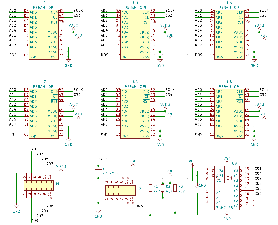
EDIT: Updated with revised pins for bank select nibble and SCLK.
How big are these memories @evanh ? Is it 8MB or 16MB per device?
Take your pick. I've not ordered any parts. I'm assuming HyperRAMs will fit also.
Well 16MB is a better match for my bank size in my driver if you need contiguous banks. 8MB will incur some foldover currently, but for single bank setups this is not typically an issue.
Doesn't seem like you save any IO pins with the 138 decoder in the 6 device setup, this board still burns two 8 bit expansion ports and has 3 IO pins left.
Yep, I liked the nibble approach above. So two spare I/O for something else. Could make the board larger.
EDIT: I suppose DQS could be moved to high bit of the nibble. It'll default as an input during bank select. That'll free up the third I/O pin. EDIT2: Maybe SCLK would be better choice. Its OUT is overridden by the clock smartpin.
EDIT3: Done. The post (#116) with files attached is updated.
Tried to run MegaYume with the 24 MB (3 chip, 4-bit) module today.
Doesn't seem to work with any of these settings I've tried:
Did test with @rogloh 's video test at the same clock freq and that works...
Added pullup resistors on the other two chip's CS lines, but that didn't help.
Might try removing the two unused chips.
Or, maybe wait for @Wuerfel_21 and @rogloh to get their modules and figure it out...