

RFID Using RC522
 Greg LaPolla
Posts: 325
Greg LaPolla
Posts: 325
in Propeller 2
I have converted an arduino driver for the MFRC522 to spin2. I have been struggling on this for a few months. I ran teh init procedure on the arduino and on the propeller 2 and there are a few registers that have different values.
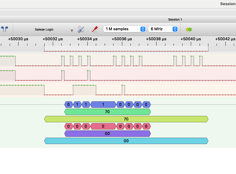
Below is a logic analyzer output and it appears there are some issues with the clock. I am using Jonny Macs spi driver. There seems to be a delay in the middle of the transfer on the 4th bit. Also when I run the logic analyzer nothing resembles the data I am sending.
Also not shown in this capture but there is a bit of mosi and miso activity when the cs is high.
Any insight is greatly appreciated!
Code is also attached. Its littered with lots of debug and notes
Comments
Hi Greg,
This may not be your issue, but one possible other issue I see is your SPI bus speed vs your LA's capture speed. In mfrc522.spin2, it looks like _khz is set to 4000 (4MHz), but your capture speed is only 6MHz. In my experience, I needed a much higher sampling rate than the signal of interest in order for captures not to have a strange looking cadence (or to not miss samples altogether). Can you try setting this higher if your analyzer supports it (or the SPI bus speed lower, if only for experimentation)?
Cheers,
Jesse
I ran another at 12 mhz. It looks a little better. If you look at the PCD_INIT method after E8 it should be 2A 40 but its 54 80.
5480 is 2A40 << 1. I can't tell with the zoom in the attached pic, but that could either be the sampling point in the logic analyzer (in other words, CPHA may be set wrong in the SPI decoder) or the data is coming out of the prop incorrectly (my guess is it's the SPI decoder setup in Pulseview).
Only the address is shifted ie. $15 << 1 would be 2A. The value being set is not shifted. The LSB needs to be 0 hence the shift.