

Class module for Waveshare LCD + utilities
 Unsoundcode
Posts: 1,532
Unsoundcode
Posts: 1,532
1 The Module
For a very reasonable cost it is possible to include a TFT LCD into your projects and have a good looking color display by which to view all different kinds of information. In particular I want to share what I have learnt about the Waveshare 1.8 inch display module for microbit
https://www.waveshare.com/1.8inch-lcd-for-micro-bit.htm
This information is not limited to the Waveshare module but will work for other modules that have the ST7735 driver
The Waveshare module is great for plug and play and has a decent amount of SRAM to help us out. Display and ram are accessed through a SPI connection.
So that we keep to the same page the class module below should be saved as a file called TFT.py, we can rename these files to whatever we want at a future date. The name is important for now because we are going to import the module into our test programs. If you need more information on importing modules into you programs then that is something we can discuss. The test program can be saved as a python file with any name you choose.
Module Code
# TFT.py .... a class module for initializing the 1.8 inch Waveshare/microbit LCD

from microbit import *

# spi.init(baudrate=10000000, bits=8, mode=0, sclk=pin13, mosi=pin15, miso=pin14)
# uBit pin 1 = lcd backlight an analog signal
# uBit pin 2 = sram cs pin low for select
# uBit pin 8 = lcd reset pin
# uBit pin 12 = lcd data/command hi for data low for command
# uBit pin 16 = lcd cs pin low for select

LCD_WIDTH = 160
LCD_HEIGHT = 128

FONT_WIDTH = const(6)
FONT_HEIGHT = const(11)
FONT_PIXEL_CNT = const((FONT_WIDTH * FONT_HEIGHT) * 2)

SRAM_READ = 0x03

class LCD:
    def __init__(self,spi):
        self.spi = spi

    def init_lcd(self):
        pin8.write_digital(1)
        sleep(1)
        pin8.write_digital(0)
        sleep(1)
        pin8.write_digital(1)

        # ST7735R Frame Rate
        self.WriteReg(0xB1)
        self.WriteData_8Bit(0x01)
        self.WriteData_8Bit(0x2C)
        self.WriteData_8Bit(0x2D)

        self.WriteReg(0xB2)
        self.WriteData_8Bit(0x01)
        self.WriteData_8Bit(0x2C)
        self.WriteData_8Bit(0x2D)

        self.WriteReg(0xB3)
        self.WriteData_8Bit(0x01)
        self.WriteData_8Bit(0x2C)
        self.WriteData_8Bit(0x2D)
        self.WriteData_8Bit(0x01)
        self.WriteData_8Bit(0x2C)
        self.WriteData_8Bit(0x2D)

        self.WriteReg(0xB4)  # Column inversion
        self.WriteData_8Bit(0x07)

        # ST7735 Power Sequence
        self.WriteReg(0xC0)
        self.WriteData_8Bit(0xA2)
        self.WriteData_8Bit(0x02)
        self.WriteData_8Bit(0x84)

        self.WriteReg(0xC1)
        self.WriteData_8Bit(0xC5)

        self.WriteReg(0xC2)
        self.WriteData_8Bit(0x0A)
        self.WriteData_8Bit(0x00)

        self.WriteReg(0xC3)
        self.WriteData_8Bit(0x8A)
        self.WriteData_8Bit(0x2A)

        self.WriteReg(0xC4)
        self.WriteData_8Bit(0x8A)
        self.WriteData_8Bit(0xEE)

        self.WriteReg(0xC5)  # VCOM
        self.WriteData_8Bit(0x0E)

        # ST7735 Gamma Sequence
        self.WriteReg(0xE0)
        self.WriteData_8Bit(0x0F)
        self.WriteData_8Bit(0x1A)
        self.WriteData_8Bit(0x0F)
        self.WriteData_8Bit(0x18)
        self.WriteData_8Bit(0x2F)
        self.WriteData_8Bit(0x28)
        self.WriteData_8Bit(0x20)
        self.WriteData_8Bit(0x22)
        self.WriteData_8Bit(0x1F)
        self.WriteData_8Bit(0x1B)
        self.WriteData_8Bit(0x23)
        self.WriteData_8Bit(0x37)
        self.WriteData_8Bit(0x00)
        self.WriteData_8Bit(0x07)
        self.WriteData_8Bit(0x02)
        self.WriteData_8Bit(0x10)

        self.WriteReg(0xE1)
        self.WriteData_8Bit(0x0F)
        self.WriteData_8Bit(0x1B)
        self.WriteData_8Bit(0x0F)
        self.WriteData_8Bit(0x17)
        self.WriteData_8Bit(0x33)
        self.WriteData_8Bit(0x2C)
        self.WriteData_8Bit(0x29)
        self.WriteData_8Bit(0x2E)
        self.WriteData_8Bit(0x30)
        self.WriteData_8Bit(0x30)
        self.WriteData_8Bit(0x39)
        self.WriteData_8Bit(0x3F)
        self.WriteData_8Bit(0x00)
        self.WriteData_8Bit(0x07)
        self.WriteData_8Bit(0x03)
        self.WriteData_8Bit(0x10)

        self.WriteReg(0xF0)  # Enable test command
        self.WriteData_8Bit(0x01)

        self.WriteReg(0xF6)  # Disable ram power save mode
        self.WriteData_8Bit(0x00)

        self.WriteReg(0x3A)  # 65k mode (RGB 565)
        self.WriteData_8Bit(0x05)

        self.WriteReg(0x36)  # MX, MY, RGB mode
        self.WriteData_8Bit(0xF7 & 0xA0)  # RGB color filter panel (result = A0)
        self.WriteReg(0x11)
        sleep(1)

        self.WriteReg(0x29) # Turn LCD on


    def clear(self, color=0xFFFF):
        self.set_window(0, 0, LCD_WIDTH, LCD_HEIGHT)
        self.set_color(color, LCD_WIDTH + 2, LCD_HEIGHT + 2)

    def set_backlight(self, level=1000):
        pin1.write_analog(level)

    def WriteReg(self, register):
        pin12.write_digital(0)  # EN LCD command
        pin16.write_digital(0)  # EN LCD CS
        self.spi.write(bytearray([register]))
        pin16.write_digital(1)  # remove LCD CS EN

    def WriteData_8Bit(self, data):
        pin12.write_digital(1)  # EN LCD data
        pin16.write_digital(0)  # EN LCD CS
        self.spi.write(bytearray([data]))
        pin16.write_digital(1)  # remove LCD CS

    def WriteData_Buf(self, color, length):
        col = bytearray(3)
        col = color.to_bytes(2, "big")
        pin12.write_digital(1)  # EN LCD data
        pin16.write_digital(0)  # EN LCD CS
        for i in range(length):
            self.spi.write(bytearray([col[0]]))
            self.spi.write(bytearray([col[1]]))
        pin16.write_digital(1)  # remove LCD CS EN

    def set_window(self, Xstart, Ystart, Xend, Yend):
        # set the X coordinates
        self.WriteReg(0x2A)
        self.WriteData_8Bit(0x00)
        self.WriteData_8Bit((Xstart & 0xFF) + 1)
        self.WriteData_8Bit(0x00)
        self.WriteData_8Bit(((Xend - 1) & 0xFF) + 1)

        # set the Y coordinates
        self.WriteReg(0x2B)
        self.WriteData_8Bit(0x00)
        self.WriteData_8Bit((Ystart & 0xFF) + 2)
        self.WriteData_8Bit(0x00)
        self.WriteData_8Bit(((Yend - 1) & 0xFF) + 2)

        self.WriteReg(0x2C)

    def set_color(self, color, width, height):
        self.WriteData_Buf(color, width * height)

    def lcd_fast_write(self, buff):
        pin12.write_digital(1)  # EN LCD data
        pin16.write_digital(0)  # EN LCD CS
        for val in buff:
            spi.write(bytearray([val]))
        pin16.write_digital(1)  # remove LCD CS

    def draw_pixel(self, x, y, color):
        self.set_window(x, y, x+1, y+1)
        self.WriteData_8Bit(color >> 8)
        self.WriteData_8Bit(color & 0xFF)

    def draw_point(self, Xpoint, Ypoint, color, Dot_Pixel):
        for XDir_Num in range(Dot_Pixel):
            for YDir_Num in range(Dot_Pixel):
                self.draw_pixel(
                    Xpoint + XDir_Num - Dot_Pixel, Ypoint + YDir_Num - Dot_Pixel, color
                )

    def draw_hline(self, x_0, y_0, length, color):
        self.set_window(x_0, y_0, x_0 + length, y_0)
        col = bytearray(3)
        col = color.to_bytes(2, "big")
        pin12.write_digital(1)  # EN LCD data
        pin16.write_digital(0)  # EN LCD CS
        for val in range(length):
            self.spi.write(bytearray([col[0]]))
            self.spi.write(bytearray([col[1]]))
        pin16.write_digital(1)  # remove LCD CS

    def draw_vline(self, x_0, y_0, length, color):
        self.set_window(x_0, y_0, x_0 + 1 , y_0 + length)
        col = bytearray(3)
        col = color.to_bytes(2, "big")
        pin12.write_digital(1)  # EN LCD data
        pin16.write_digital(0)  # EN LCD CS
        for val in range(length):
            self.spi.write(bytearray([col[0]]))
            self.spi.write(bytearray([col[1]]))
        pin16.write_digital(1)  # remove LCD CS

    def draw_char(self, x_0, y_0, char_id=0):
        offset = char_id * FONT_PIXEL_CNT
        buf = self.ram_read(offset, FONT_PIXEL_CNT)
        self.set_window(x_0, y_0, x_0 + FONT_WIDTH, y_0 + FONT_HEIGHT)
        pin12.write_digital(1)  # EN LCD data
        pin16.write_digital(0)  # EN LCD CS
        for val in buf:
            self.spi.write(bytearray([val]))
        pin16.write_digital(1)  # remove LCD CS

# Memory

    def ram_read(self, addr, read_cnt=1):
        address = bytearray(3)
        address = addr.to_bytes(3, "big")
        pin2.write_digital(0)  # CS ram
        spi.write(bytearray([SRAM_READ]))
        spi.write(bytearray([address[0]]))
        spi.write(bytearray([address[1]]))
        spi.write(bytearray([address[2]]))
        RD_Byte = spi.read(read_cnt)
        pin2.write_digital(1)  # remove ram CS
        return RD_Byte
Test Code
# Circle.py
# TFT-LCD demo
from microbit import *
import math
from TFT import LCD
spi.init(baudrate=10000000, bits=8, mode=0, sclk=pin13, mosi=pin15, miso=pin14)
WHITE = 0xFFFF
BLACK = 0x0000
BLUE = 0x001F
RED = 0xF800
MAGENTA = 0xF81F
GREEN = 0x07E0
CYAN = 0x07FF
YELLOW = 0xFFE0
GRAY = 0x9492
lcd = LCD(spi)
lcd.init_lcd()
lcd.set_backlight(1000)
lcd.clear(GRAY)
def draw_circle(center_x, center_y, radius, color):
for i in range(360):
rads = math.radians(i)
x1 = center_x + math.sin(rads) * radius
y1 = center_y - math.cos(rads) * radius
lcd.draw_pixel(int(x1), int(y1), color)
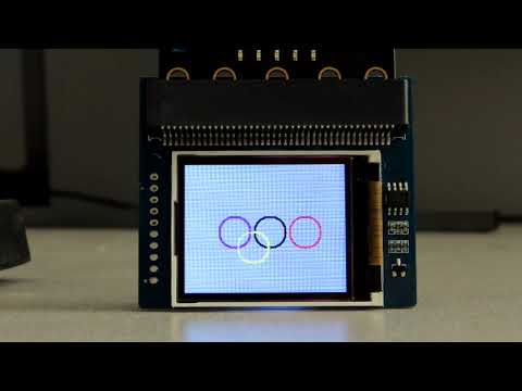
draw_circle(50, 68, 15, BLUE)
draw_circle(50, 68, 16, BLUE)
draw_circle(85, 68, 15, BLACK)
draw_circle(85, 68, 16, BLACK)
draw_circle(120, 68, 15, RED)
draw_circle(120, 68, 16, RED)
draw_circle(68, 83, 15, YELLOW)
draw_circle(68, 83, 16, YELLOW)
draw_circle(105, 83, 15, GREEN)
draw_circle(105, 83, 16, GREEN)
Comments
2 Methods
With everything we do with the microbit conserving program and storage space should be at the back of our mind, initialization of the module and its associated methods is a necessity any other modules are more likely to be program dependent.
The following is a list of methods I have been using in the TFT module, the list is not set in stone they are just the functions I have found most useful for me.
init_lcd(spi):
Initializes the LCD takes spi as argument
clear():
Clears the whole display and takes a 16 bit color value as an argument, if no argument is passed the color defaults to white.
set_backlight():
Sets the lcd backlight level and takes an int value from 0 – 1024, if no value is passed the value defaults to 1000.
set_window(Xstart, Ystart, Xend, Yend):
Defines a window (rectangle) as a drawing area.
set_color(color, width, height)
Fills a rectangle defined by "set_window()" with color, width and height are the dimensions of the window.
draw_pixel(x, y, color):
Draws a pixel at coordinates x y with the defined color.
draw_point(Xpoint, Ypoint, color, Dot_Pixel):
Draws a group of 1 to 4 pixels at x y with the defined color and the group number defined by Dot_Pixel
draw_hline(x_0, y_0, length, color):
Draws a horizontal line starting at x_0 y_0, the length is defined by length and color is defined by color. The line should be drawn left to right.
draw_vline(x_0, y_0, length, color):
Draws a verticall line starting at x_0 y_0, the length is defined by length and color is defined by color. The line should be drawn top to bottom.
draw_char(x_0, y_0, char_id=0):
Draws a font character at point x_0 y_0, the char_id references the characters position in ram.
3 Images and Utility
With the information we have so far we can initialize our LCD and draw some graphics maybe even create a few stick fonts. Images take things to another level and over the next two posts I would like to show how we can display our own images. First we need somewhere to store the images so using the Waveshare microbit device I will use the onboard SRAM.
This will involve extracting the image data from an image file and saving this data to a new file. Then we can use our micropython editor to read and write this new data file to the SRAM memory.
There a a couple of things to consider before we create this new file. First lets keep the file size below 15 Kbytes so that we dont run into out of memory issues with the microbit. The number of bytes our file will be is proportional to the number of pixels our image has. Here are two examples, the first image is 160 pixels wide and 45 pixels high, 160 x 45 = 7200, there are two color bytes for each pixel so the final file size for image 1 is 14400 bytes which is within the 15 K range, the second image is a full screen 160 x 128 which equals 20,480 pixels so that is 40960 bytes, way over limit. There are ways to get around this but for now lets keep within the 15 K range.
The microbit micropython editor won't be able create the new image data file so you will need to run the following code on a computer that has the full version of Python.
Usage is straight forward, I try to stick with source files that have the .png extension and I usually name the destination file with the .bin extension.
The following code is very basic so keep source and destination files in the same folder as the utility, there is no need to type in the full path. The libraries used in the app are very common modules and most come packaged with Python.
Utility
from tkinter import * from tkinter import ttk from tkinter import messagebox from PIL import Image import numpy as np root=Tk() screen_width= root.winfo_screenwidth() screen_height= root.winfo_screenheight() root_width=270 root_height=150 x_location=(screen_width/2) - (root_width/2) y_location=(screen_height/2) - (root_height/2) root.geometry(f"{root_width}x{root_height}+{int(x_location)}+{int(y_location)}") root.title("Data from Image") root.resizable(False,False) var_list=[] source_var = StringVar() destination_var = StringVar() def get_params(): source_var=source_entry.get() destination_var=destination_entry.get() var_list.append(source_var) var_list.append(destination_var) create_img_data(var_list) def rgb_hex565(red, green, blue): return "0x%0.4X" % ((int(red / 255 * 31) << 11) | (int(green / 255 * 63) << 5) | (int(blue / 255 * 31))) def create_img_data(var_list): var_list=var_list src_file=var_list[0] destination=var_list[1] if src_file=="" or destination =="": img_msg() return try: bin_img = Image.open(src_file) except: bad_file_msg() return img_map = np.array(bin_img) f = open(destination, 'wb') for y in range(bin_img.height): for x in range(bin_img.width): pix_color=img_map[y][x] value = pix_color[0] value2=pix_color[1] value3=pix_color[2] newcolor=rgb_hex565(value,value2,value3) bin1=int(newcolor,base=16)>>8 & 0xFF bin2=int(newcolor,base=16) & 0xFF f.write(bin1.to_bytes(1,"big")) f.write(bin2.to_bytes(1,"big")) f.close() messagebox.showinfo("Info", "File Operation Completed") close_app() def img_msg(): messagebox.showerror("Error", "Source and Destination must contain a valid filename") def bad_file_msg(): messagebox.showerror("Error", "Source not found") def close_app(): root.destroy() def on_closing(): if messagebox.askokcancel("Quit", "Are you sure you want to exit?"): close_app() root.protocol("WM_DELETE_WINDOW", on_closing) btn_CreateFile=Button(root,text="Create File",width=10,command=lambda:get_params()) btn_CreateFile.grid(row=4,column=1,pady=15,sticky='w') btn_Exit=Button(root,text="Exit",width=10,command=lambda:on_closing()) btn_Exit.grid(row=5,column=1,sticky='w') source_entry=Entry(root) source_entry.grid(row=0,column=1) destination_entry=Entry(root) destination_entry.grid(row=1,column=1) lbl_source=Label(root,text="Source File",pady=10,padx=20) lbl_source.grid(row=0,column=0) lbl_destination=Label(root,text="Destination") lbl_destination.grid(row=1,column=0) root.mainloop()Loader
Hopefully you now have a binary file containing the data for your image. I am posting here the micropython code we need to write the image data file to SRAM, I will refer to this code as the "Loader", also I am posting a small micropython code to test the success of loading the image to SRAM.
As long as we maintain power to the microbit and don't over write the image data we can switch between program sketches and access our image at any time.
I will describe the actions in a step by step fashion and hopefully it will be easy to understand.
step #1 Remove all files from the microbit file system
step #2 Copy the image file (mine is called logo.bin and is 14400 bytes) onto the microbit file system.
step #3 Close the file system and copy the "Loader" code into the micropython code editor.
step #4 At the very top of "Loader" are three fields we must fill in, FILENAME , START_ADDRESS and END_ADDRESS. For now this info has already been filled in but its important to note that END_ADDRESS = START_ADDRESS + the file length which in my case is 50000 + 14400 = 64400
step #5 Flash "Loader" to the microbit
step #6 Open REPL then press the microbit reset button, the program will start to run. REPL lets you see when the program has finished.
step #7 It takes a minute but eventually you willl see the text "*********** Write Finished ***********"
step #8 Close REPL and open the microbit file system
step #9 Remove the image file and replace it with the TFT class module
step #10 Flash the test program to the microbit and hopefully your image will load
Loader
# Loader.py .... writes files to sram

from microbit import *
import machine

# *********************************************************************************************
FILENAME = "logo.bin"
START_ADDRESS = 50000
# The end address will be the sum of the start address + the number of bytes to write
END_ADDRESS = 64400
# *********************************************************************************************

spi.init(baudrate=10000000, bits=8, mode=0, sclk=pin13, mosi=pin15, miso=pin14)
# SRAM opcodes
SRAM_CMD_WRMR = const(0x01)  # write mode register
SRAM_CMD_WRITE = const(0x02)
SRAM_CMD_READ = const(0x03)

# SRAM modes
SRAM_BYTE_MODE = const(0x00)
SRAM_SEQUENTIAL_MODE = const(0x40)
SRAM_PAGE_MODE = const(0x80)

def ram_write(addr, buff):
    address = bytearray(3)
    address = addr.to_bytes(3, "big")
    pin2.write_digital(0)  # CS fram
    spi.write(bytearray([SRAM_CMD_WRITE]))
    spi.write(bytearray([address[0]]))
    spi.write(bytearray([address[1]]))
    spi.write(bytearray([address[2]]))
    spi.write(bytearray([buff]))
    pin2.write_digital(1)  # remove fram CS

def ram_set_mode(mode):
    pin2.write_digital(0)  # CS fram
    spi.write(bytearray([SRAM_CMD_WRMR]))
    spi.write(bytearray([mode]))
    pin2.write_digital(1)  # remove fram CS

ram_set_mode(SRAM_SEQUENTIAL_MODE)

with open(FILENAME, mode='rb') as file:
    for idx in range(START_ADDRESS, END_ADDRESS):
        data = file.read(1)
        int_val = int.from_bytes(data, "big")
        ram_write(idx, int_val)

print('\r')
print("***********  Write Finished  ***********")
print('\r')
Test