

ADC thermal stability, sampling rate, and pushing it's limits
 n_ermosh
Posts: 303
n_ermosh
Posts: 303
Has anyone done testing to push the limits of the smartpin ADC? I've been slowly trying to see what I can do with it and have come up with the following questions:
1) how often does vio/gio calibration need to happen? Other than temperature, is there anything that can cause ADC's measurements to drift relative to vio/gio, requiring them to be remeasured?
1a) how stable is the ADC over the P2's temperature range?
2) How fast can a signal reasonably be sampled? I understand that I can set the rate at which is the ADC is grabbing samples and writing them to the pin's Z register, but how does that translate into reality? For example, I know that when I switch between sampling the pin, sampling gio, and sampling vio, I need to take 3 samples before the output is actually stable. I've also done tests where if I step the input from 0 to 3.3V (using an adjacent pin), it also takes about 3 samples before the result reads 3.3V
3) Is there a way to trigger exactly when the ADC starts taking it's next sample? Currently I can only see that I can release it from reset and it's going continuously, but if I need to synchronize it to specific events, there's no I can tell to set it to start sampling at a specific time, other than resetting, which then means 3 samples are needed to stabilize the value again.
4) when using sinc2/sinc3 modes for improved dynamic response, the docs show an example where that's the only thing the cog is doing and it's servicing every adc sample. Is this required, or can I pull every nth sample and perform the additional computation then?
5) is there any kind of voltage holding mechanism in the ADC? if the value on the pin shifts throughout a sampling period, will is affect the resulting sample (likely resulting in just reading the average over the sample period)? Must the external signal be filtered such that it can not appreciably change over a given sample period, or can it change and just the next sample window will capture the voltage and hold it (likely leading to aliasing issues)?
For reference, these questions are coming from my working on an FOC motor control implementation. I'm doing low side measurements so in many cases, the low side switch is on for a brief period of time and therefore I only have a small window where I can actually measure the voltage across the sense resistor.
Comments
This is something like delta-sigma ADC: the signal is sampled every CPU clock. The result is a bit stream, where the density of 1s is proportional to the input voltage.
You can then do several things with it:
-simply count ones in a desired period of time
-use one of built-in filter modes, where the smart pin does prefiltering for you. Then you also set a period of sampling time in clocks.
1
1a: I don't know
After changing the signal source 2 processes can make you wait for the correct sample. The first is the analog input circuit which has its own time constant, the second, and more important, is the SINC filter which have to stabilize.
The short answer is no, but in reality the way to achieve this depends on what sample rate you want to use.
SINC2/SINC3 raw output data needs additional processing by the cog which needs all output samples to do the job.
The value will be averaged.
How to measure the voltage across the sense resistor depends on (1) what resolution you need (2) how brief is this period (3) what is the voltage on the resistor when the switch is off.
(*) practically, not faster than sample rate/16 (4..8 bits precision), which gives 20 MHz sample rate
(**) SINC filters limit the lowest possible sample rate to 512 clocks using SINC3 and 8192 clocks with SINC2, but you can still process these samples to get lower sample rate and higher precision.
Thanks for the thorough reply.
For 1), I ran a test today and let the ADC collect values for the last 6 hours, calibrating for vio/gio only once and letting it run, comparing new values to the initial value. I need to formalize the results and actually look at the data over time, but first glance there's no change. So at a minimum, at constant temperature, vio/gio measurements don't need to be repeated. I'll repeat this with temperature variation as well. Need to figure out what that experiment will look like.
Okay, I'm starting to get a clearer picture of how the ADC system actually works. The ADC itself is not a smart pin mode, but can be enabled with the low-level pin control (wrpin). It creates a bitstream at the system clock frequency which needs to be sampled. The smart pin modes are just a convenient (and basically only) way to actually convert this bitstream into a sample. Is this correct? Probably a lot of cool tricks that can be played there too, if you utilize other pin functions with the ADC enabled. Also raised the question, how does the drive circuit (which is connected to the pin internally) play into the ADC's readings? Or does turning on the ADC sampling smart pin disable the drive circuit?
So I'm curious what would happen if I did "burst" reads of the sinc3 mode. For example, did the computation loop 3 times when in 32 clocks/sample mode. Will this still yield a 10 bit result after 96 clock cycles, as opposed to 512 clocks when using sinc2 sampling or sinc2 filtering? If not, how long must the sinc3 filter be running (with the extra computation) before the extra integration and differencing yields a 10 bit result? Really, this goes to the question of how long does it take the filter to stabilize? With sinc2 sampling, no matter how long I make the sample period, it always takes 3 samples for the filter to stabilize (so the analog front end is not dominating here). My understanding is that sinc2 sampling is just counting the number of 1's in the bitstream, while sinc2 and sinc3 filtering actually perform some filtering on top of that to improve dynamics or DC stability.
For my specific problem: I need 9 bit resolution, and I can choose the minimum on time, but with my current setup, at 18.3KHz PWM frequency and wanting to let the duty cycle go as low as 5%, this comes out to 2.75us, or 825 clock cycles (system clock is 300MHz). Assuming some overhead and 3 samples necessary to settle after a switch event, that's 256 clocks/sample I'm allowed. In terms of voltage when off, it's currently 0V, but I'm also going to get a current sense amp with an adjustable reference point, so I can play with changing that. Now, I want to increase my PWM frequency (there is a 9Khz subharmonic popping up due to my commutation scheme that make audible noise I'd like to eliminate). decreasing the PWM period means I violate my 5% duty cycle requirement. So I'm at a limit right now.
I can't respond in detail to this due to time pressure right now, but regarding question 1, evanh plotted some data from some early sweeps we did,
https://forums.parallax.com/discussion/download/124010/20-300%20Mhz%20%2859%20pins%29A.png
This shows the the behaviour of GIO and VIO against temperature (operating frequency) varies according to the pin. For some pins that don't wander much, you could just lock in a static value of VIO and GIO and do quite well, but we never went back to see how these paths vary on different dies from the same/different batches
The other thing to mention is Richard Morrison (rjsm) put together a ~10 page analysis of the P2 ADCs, bringing their data into that national instruments tool to analyse. I need to locate this in the forums, it's here somewhere... later
Thanks for the link. And I hope you are able to find that document once you have time, that will be incredibly useful.
@n_ermosh ...
... perhaps some kind of "thirteen-month-déjà vu-recursive-question" ...
https://forums.parallax.com/discussion/comment/1522668/#Comment_1522668
As usual, hope it helps.
Henrique
Yes, you've saved me again thanks Henrique!
And once again its 18 rather than 10 pages. Struggling to read-modify-write my own brain on this.
Awesome! looks like I've got my bedtime reading
You're welcome Lachlan!
By the past 16 days, i've been experiencing some frightening hearing losses at my left ear (the one that usually listens to what evil whispers), but the right-one did saved my memories, once more (the one that listens to what Mary, the Mother of Jesus, uses to tell me)!
The first idea is: (1) to not use any filtering. The mode is not described in the manual, but somewhere in this forum. Simply count ones in 1024 clock periods. (2) you will get a stream of GND samples and sometimes 1 or 2 samples containing the actual signal, (3) you can now compute the voltage value at about 9 bit resolution.
Hey, I'm doing the exact same thing.") See this project.
See this project.
From my experience, there is not only thermal drift but also kind of random low frequency noise. If you need really precise DC measurements you have to calibrate something around 100 times per second. So you need two ADCs per analogue signal and swap the measuring and calibrating pin frequently. Be aware that there remains a small offset error (~6mV 20mV) even with calibration. (explanation here)
However, if you sample the voltage at a low side shunt resistor to measure current of a FOC power stage you don't have to care about (on the fly) calibration. You can do this once after power on to calibrate the process variations of the silicon. Offset cancels out automatically if you sample once in the middle of the on-state and once in the middle of the off-state of the low side MOSFET. As you know that the current is zero during the off-state you can take the difference of both samples and you have automatic offset calibration. Gain calibration can be completely ignored because the torque/current factor of the motor has 10% or more tolerance anyway and the gain error is removed by the PID loop of the velocity controller.
No. If you absolutely need a shorter sampling window than, say, around 1µs then it's better to use an external S/H ADC.
Good question. I think we need to do some experiments to find the sweet spot. I currently plan to use 200MHz system clock and 12kHz symetrical PWM which means that each frame (up/down slope) of the PWM counter takes 40.96µs or 8192 clocks. Symetrical dual slope PWM has the advantage that the current ripple has twice the frequency of the PWM switching frequency so the main sound emittance is well above the audible range (24kHz).
I can take 32 ADC samples of 256 clocks during each PWM frame. If the minimum off time of the low-side switch is 6.25% I can take 4 samples at the center between frame 1 and 2 (low switch on) and 4 samples between frame 2 and 3 (high switch on). The first two samples of each group of 4 I have to throw away when using SINC3 filtering.
SINC3 gives best ENOB and lowest noise but requires to drop two samples after a switch event. SINC2 would allow to use more samples or using a shorter min. off time window. We have to find out which is better.
You can reset the pin to synchronize it but you don't have to. At least not if you use a fixed PWM frequency. In this casse you always want to center your sample window between two PWM frames so that the current is measured in the center of the all-half-bridges-off or the center of all-on state. This is where the motor current is close to the average value.
Another thread about adc operation from about 1 year ago: https://forums.parallax.com/discussion/comment/1523646#Comment_1523646
TLDR - 511 is the maximum sinc3 sample interval if you don't want want saturated positive and saturated negative to output the same value.
Personally I prefer to process ADC samples at maximum bit width. Quantizing the samples adds noise. Right shifting is quantization. You don't get close to the specified bit width in the datasheet after shifting anyway. The full scale output value is N² for sinc2 and N³ for sinc3. Full scale should be less than the $07FF_FFFF mask used to process the sinc output.
1a. IDK
2. Using the scope filter 12 MSPS is doable. There is some high frequency rolloff. The 68 tap filter should give 6 bits real data bits.
3. In scope mode, read it anytime and get a windowed sum of the last N samples.
4. Just let it run and start collecting samples when you want to start sampling?
5. No
Sinc1 is a Rectangle
Sinc2 is an Isosceles Triangle
Sinc3 is where it starts approximating a Gaussian
This reminds me of a certain XKCD.
Situation: There are 25 threads about the ADC.
Problem: It's too much work to look through all these old threads.
Solution: I'll create a new thread.
New Situation: There are 26 threads about the ADC.
We had a discussion about whether window filters can actually increase the bit resolution. Since the P2 has a first order modulator, the answer is no. We did some simulations and there were some bad non-linear steps at rational fractions. Around fractions like 1/2, 1/3 there were highly non-linear steps. These were simulations and the noise in a real modulator might help reduce the effect. If you want 8 real bits of data, for instrumentation applications, then you need a sampling period of 255 clocks. You still need to use a window filter for low pass filtering. The 255 bits summed together results in 256 unique values. With a window filter you can get many more than 256 unique values if you have the bits to represent them. For audio, video, and signal processing applications, the window filter is fantastic at reducing the average quantization noise and actual noise from outside the frequency range of interest.. The peak quantzation noise is still 1/N or something like that.
< deleted, OT >
As Pik said, all accumulator decimations have to be collected and processed to build valid PCM samples. However, you get to specify the decimation period. Accumulators are 27-bit, so max period is: Sinc3 = 511 sysclock ticks, Sinc2 = 11585 sysclock ticks. Actually, max period is dependant on working voltage range. If you only allow half the range electrically then max decimation period can be doubled.
Nope, but the hardware can't alias unless your sysclock is set lower than the modulator's natural cut-off - which is around 2 MHz I think. As Pik says, you get the average voltage for that decimation interval.
Spot on!
Can be done with streamer in a couple of ways also. But yeah, bitstream has to be gathered at sysclock rate to work.
EDIT: And there's the GETSCP instruction as well. I've not tried it out. It works in conjunction with the "scope" smartpin mode. James mentioned this above. Might be just what you're after.
Logic output drive, via DIR control, still functions (Interesting point, I had though otherwise for some reason) - https://forums.parallax.com/discussion/171420/smartpin-diagram/p1 It can be used to switch the input to GIO and VIO levels.
Schematics of pin internals - https://forums.parallax.com/discussion/comment/1494131/#Comment_1494131
and - https://forums.parallax.com/discussion/comment/1510744/#Comment_1510744
My maths is Smile but I do know that, starting afresh, as in switching from VIO to GIO for example, three decimations of Sinc3 is only enough for a single PCM sample. You have to keep taking more decimations to build a series of samples. What's more you also must discard the first decimation as this will contain some signal from prior voltage source. So that's really four decimations to get the first sample.
Umm, there is something called ENOB (Effective number of bits). The result size is a lot bigger than the ENOB. With Sinc3, the numerical resolution is as cubic as the filter is. For example, decimations of 32 clock ticks long gives you a 15-bit result on every decimation (after settling). But ENOB is supposedly 6 bits. I don't know the maths sorry.
Problem with taking faster samples is you are left with a series of samples that still need further filtering for any extra amplitude boost.
Sinc2 "sampling" mode includes the decimator hardware. You don't have to worry about collecting every decimation when using that mode. The same Sinc2 filtering function otherwise. So is also subject to the Sinc2 settling time.
There is a Sinc1 mode elsewhere: P_COUNT_HIGHS, (%01111). This is the simpler collect 1's type operation.
PS: My best recommendation is get up to speed with everything ManAtWork has done.
You can not get the information from nowhere. The sinc3 filter magic giving 2x more ENOB than really sampled bits works because of the filter internal memory, so it has to be fed first. To have 10 bit resolution you have to gather 1024 samples and feed the filter with them before the filter can do its magic at the full power.
If there is limited time for one shot measurement, the sinc1 mode is the best for it. Any filter used for one shot measurement will only make the precision worse.
Lots of information to digest here!
I think the thing I want to look into the most is doing all decimation in software and just counting high bits coming from the ADC. This lets gives me the most control over when samples are taken, how long things take to settle, etc. I need to brush up on my ADC and sampling theory. Now I wish I had paid attention in my DSP lectures...
Okay so I think I get it--the point of the sinc3 filter is that you can get new samples every 32 clocks at 10 bits of resolution, but only because of the internal FIR filter (or IIR?) in the smart pin hardware being continuously run and the software constantly updating its half of the filter. If you stop updating the software side, you lose the extra resolution. So to get 10 bits of data, you need to have 1024 clocks no matter what, but you can get new samples in 32 clocks with a phase delay. Correct?
@ManAtWork I'll need to take some time to dig through all your work so far and see what you've done, but I think we have a lot of the same ideas--symmetric PWM and measure on the center of the low side frame. I'm assuming you are also doing 3 phase brushless motors? I'm also trying to do it all with a single P2 rather than a peripheral P1 for the power stage. I think it has enough power to do it all. But we'll find out!
You're method of calibrating by using the off-measurement for the offset is interesting, I hadn't thought about that. What's more is I'm doing FOC with a single sense resistor in DC, and varying the phase shifts of the PWM to get a specific pattern of which low side fets are on during each PWM cycle, so I can reconstruct the phase currents in 12 cycles. In there, I naturally need to subtract pairs of current samples, so I can get the same offset correction for free. You are probably right that gain correction is unneeded, but I do need (relatively) accurate torque control without the higher level velocity loop, so if there's a 10% error on the torque constant of the motor + 10% error in current measurement, I could be off by 20%, which is likely not acceptable (but I'll have to try it to find out), but doing a single measurement and just absorbing the error due to thermal drift is probably okay.
2Mhz is a very important number to know, thanks.
What about when the ADC smart pin mode is enabled? does that override the fact that DIR is high (to enable the smart pin) and disable the output control circuit? or would I need to switch the output control to floating so that it's not driving the pin?
Sadly that is the state of things. I think we all hope that the information in the forums gets consolidated into proper documentation that's easy to read and follow, rather than sifting through discussions to find nuggets of information, but no one's got the time to actually do it. Maybe one day...
If you really want to go to town on software filtering then a streamer can store the raw bitstream in hubRAM.
No issue there, there is a specific mode bit for setting output enable when using a smartpin. I just realised it was the OUT, not DIR, that I thought wasn't there. It gets confusing remembering what can and can't be done together. There is definite combinations that can't be done simply because of limited number of mode bits.
So, with ADC and SincX smartpin operating, OUT works as normal and DIR enabled the smartpin. To enable the pin output, set bit6 of WRPIN mode, pre-defined constant P_OE.
Yes, but the next best thing for now is to make sure info the info is at least shared here. Several of us have done a dive into the ADCs with our own application in mind, and over time there's more and more understanding of whats possible. From my point of view the thing I wanted to do next was look at the variation from chip to chip for things like GIO/VIO behaviour
On the rolloff frequency I think we found it more like 4 or 6 MHz, but didn't measure precisely
I'm so very familiar with that particular XKCD...
this one?
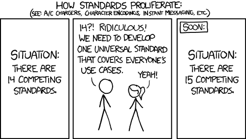
Yes
I remember there used to be a Propeller Wiki.
Yes, it was origionally designed as servo drive for permanent magnet brushless motors but as there is currently a severe supply problem with VFDs I think I'll implement squirrel cage induction motors first. They are a lot easier because the starting position of the rotor doesn't matter and you can run them open-loop without position feedback.
Yes of course, the P2 has enough power to do it all. The reason for the P1 in my design is the isolation barrier. The P2 has to be connected to the power stage domain because of the analogue signals unless you want to use complicated and expensive analogue optocouplers or external ADCs. If your motor runs on low voltage like the hoverboard motor does you can connect everything (encoder feedback, command input, IO) directly to the P2. If the motor runs on mains 230VAC voltage you can't without using a lot of optocouplers. The additional P1 has the advantage of requiring only a single ISO7721 full duplex data coupler.
I know that trick but I thought it was used mainly to save money and pins of very restricted uCs. A shunt resistor in the milliohm range only costs $0.10 and the P2 has abundance of ADC pins. So why being stingy? Being able to measure all three phase currents simultanously makes the software much simpler and less sensitive to noise and other errors.
The main reason for gain errors are process variations of the motor production, silicon chip production and shunt resistor tolerance. Second important effect is thermal drift (weakening magnetic field in the motor and changing resistor values). You may have a worst case error of 20% but it becomes much less if you do a static calibration once on startup.
If you have a closed loop system like a servo with position feedback then even 20% doesn't matter at all because the velocity and position feedback loop eliminates any torque error. You have to counteract external forces like drag or gravity for sloped or vertical movements, anyway, and those are likely to be much bigger than the torque error.
Makes perfect sense. I'm only doing 28V motors so no problem.
It's a long story involving supply chain issues that I won't get into. But you are 100% correct, no need to be stingy with it. on my production design it will just be 3 independent measurements, but until I get those boards I need to make progress on the software side with what I have (parallax's motor driver board) which only has the single measurement.
Yeah in a closed loop servo with position/velocity feedback the gain error gets corrected out. But when in a torque-only control mode (which I need for my project), that error doesn't get controlled out, and 20% starts becoming noticeable.
Back to ADCs.
I was thinking about this more last night and I don't actually need the ADC/signal itself to be super high performance, I just need the ADC to sample really fast. The fact that I'm measuring a current with a ~1ms time constant actually helps a lot, so my plan is to take short measurements by just counting ones over a short period of time (like 256 clocks, likely) over multiple PWM cycles and decimate using an IIR filter (not linear phase, I know, but if it becomes a problem, I have the processor bandwidth to implement an FIR windowed-sinc filter if needed). Which is basically what the sinc2/3 modes are doing anyway, right? Just I control the sampling rates into the filter a bit more precisely. So across say 4 pwm cycles, I get my 1024 clocks measured and the current signal itself will basically be constant during the measurement window. (I need to do the math on how much error I will actually get in the measurement across 4 pwm cycles to make sure it's not crazy, but I think it should be fine.
And if this never gets better, that could relegate the P2 to a nice experiment that just did not work out. Hope not, the P2 is one awesome part.
quick update, my theory above worked. I'm able to get the resolution and precision I want by taking 128-clock samples and filter them together to get a 12-bit resolution, 10-bit precision sample, using just a simple IIR low pass filter for the decimator before down-sampling in my control loop. P2 is a really, really awesome piece of hardware.