

Response to: Parallax's Brushless DC Controller System for Hoverboard Motors
 Mickster
Posts: 2,935
Mickster
Posts: 2,935
1) Last time I checked, not available in UK (Digikey, Mouser)
2) To be "universal", It needs to directly accept pulse/direction commands to cater to those who would like to upgrade from stepper-motors to closed-loop servos; LinuxCNC, Mach4, not to mention the low-cost Fanuc clones coming out of China.
3) We're going-up against ODrive and VESC
4) How about some serious HP?
JMO.....Too old to get excited about hoverboards ![]()
Edit:
Would be nice to have an P2 alternative to the "ST MCU board":
https://uk.farnell.com/stmicroelectronics/steval-ipmm10b/eval-board-ac-induction-motor/dp/3489469
Comments
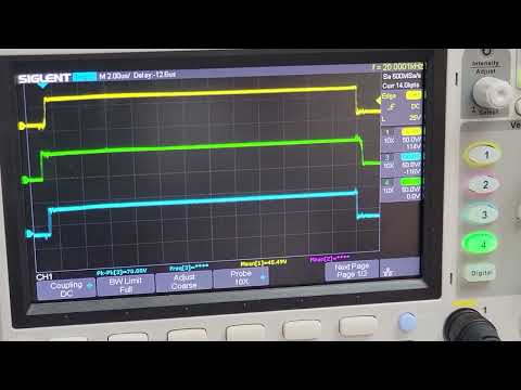
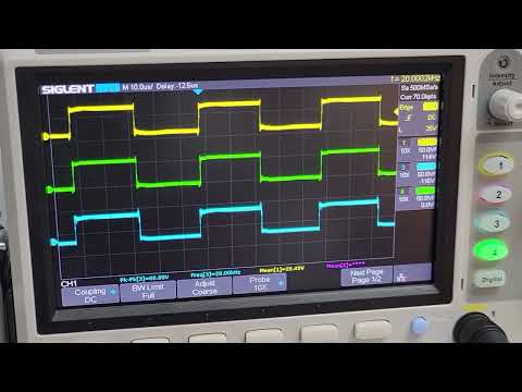
About a year ago I did some reverse engineering of some BLDC motor drivers from China with very little documentation and little support other than a few handful of packet commands I could send to the controller. I had an epiphany that was like a train running through my living room. Everything that I had searched for on line suggested that the three wave forms were always 120 Deg out of phase from one another. Definitely not the case with this motor controller. Imagine all three phases moving in the same phase, the motor doesn't move BUT it is locked to it's position. Well sort of.... in order to truly lock the position you need to implement an encoder for the position feedback. ... anyway back to all three phases moving together. What this does do is create an electric brake. Just like when you short the leads of a DC brush motor together and try to spin it. Now with that said the 120 Deg phased sine wave relationship is between each phase. The signal on each phase is still a square wave. So as it turns out there are two things that can happen here with the phase relationship. ONE is the speed you cycle through the sine table.... this speed obviously dictates the speed of the motor. And TWO the magnitude or amount of Phase offset determines the strength or torque of your motor. I had mentioned earlier about positioning feedback .... If you want to dynamically hold a position, then read the position feedback and if it goes in one direction from where you want to be then actively drive the phase in the opposite direction. The result is that the motor will dynamically fight you to hold the target position.
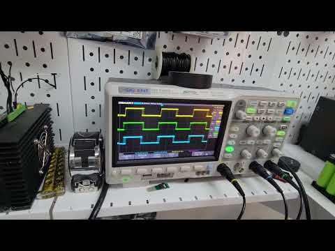
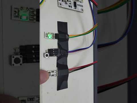
Here are a few videos to hopefully explain the concept a little better. The code is written in a PIC16F15323 in assembly, but could conceptually be written in P1 or P2.
Note: The "fast" turning video has a pop sound from the frame holding the motor and the motor balance being slightly offset.
Closeup:
Slow turn:
Fast turn:
@"Beau Schwabe"
Most of the time I have difficulty deciphering @ErNa's posts but I believe that this is similar, if not exactly the same as what he has going.... very cool indeed
What brand of driver was that?
The original driver was a ZLAC8015 Servo Driver. What you saw in the video was our own design.
Here is another video a little more refined for the Clients specific application need.
"The reception on this is humbling quiet so far. We have lots of resources into the project, too. Tell me what you think: not of interest at this time, maybe watching and learning, thinking of getting involved, etc. Tell us what's on your mind, whatever it is."
If you sum up all parts of this then such project will be in a range of perhaps 700$ including batteries. So this is rather high for a pure hobby fun project. So this is somewhere in between a hobby thing and a professional thing. The motors are fast and powerful enough to damage something, so using a breadboard is rather questionable.
For professional usage, I think some information about the load carrying capacity of the wheels together with bearing life information would be needed. I do not think, that these mounting blocks and their intended fixing to a frame is fit to deal with the torque and load.
Probably a controller board for 800W peak needs additional hardware protection features?
All in all I think, this seems neither for hobby nor for professional?
I bought just the motor driver board because I already have a regular supply of only marginally damaged brushless DC motors, but I've been too busy with other things to do much with it so far.
I'd also like to use it at least as a prototype for a digital AC inverter to power standard postwar Lionel trains with their universal brushed motors. It will provide current control for more realistic acceleration and will use current/voltage feedback to track the motor commutator position for exact train position information, and then it will also use this info to try to sync the AC waveform with the motor commutator to minimize the pole current when the commutator switches in order to wear the motor brushes less. But I'd need to keep the P2's GND at least 20V below the track neutral for this unless I design my own board. I should probably build the actual layout first before I bother doing too much work on this...
Methinks that we need to be on the
https://www.simplefoc.com/
Bandwagon.
They are already struggling with limitations that the P2 doesn't have.