

SD card noise
 Wuerfel_21
Posts: 5,868
Wuerfel_21
Posts: 5,868
This is something that always mystified me: How to stop the squealing-type sound of an SD card being accessed from crossing over into analog audio outputs?
I get loads of it on my P1 board (presumably due to poor routing of the 3v3 rail), but even the P2EDGE with its separated VIO regulators doesn't cut the mustard. It's not at a level where you'd really notice it while actual sound is produced but very obvious against supposed silence.
Yet I don't recall ever hearing it on a "proper" device like a phone or MP3 player. Only other ref that I can really find on this is that certain game console CD drive emulators are also affected by the issue and in relation to that people have found that SanDisk cards (like I use) are especially loud, but also do not exhibit the intermittent latency spikes some other brands apparently have. Huh.
Comments
P2 analog out uses 3v3 as the reference, so PSRR is poor, but it's surprising the separate 3v3 regulators are not enough to reduce this.
Did you measure the 'noise floor' for the different locations of regulator ? Maybe there is just enough common mode ground impedance on some ?
Most likely you are experiencing the noise coming from L401(6A top rate) or L403 (4.2A top rate), the two inductors thru where the current that feeds every other of the eight 3.3V LDOs passes.
L401 is also responsible for feeding power to the VDD regulator, whith its L402 (also 4.2A top rate).
Despite I've been suffering from otitis at the timpanic membrane of my left ear (the best one) for a painful week long, I know by experience you can spot from where the noise is comming by means of a hard stick or tube, touching the top surface of the inductors, and pressed against some amplifying metalic sheet, like a jam pot cap.
The hard tube don't need to be metallic; glass or quartz are fantastic, hard epoxi too, and even an old-style "Bic" pen, (cap, tip and back seal removed) will work fine.
P.S. Or... buy one of these, but, watchout, the tip is metallic, so it can cause weird short circuits elsewere.
https://amazon.com/Lisle-52500-Mechanics-Stethoscope/dp/B0002SQYSM
Further info on the subject:
https://product.tdk.com/en/techlibrary/solutionguide/acoustic-noise.html
Hope it helps
Henrique
Don't really have anything that could really measure it. The line-in on my PC is too inherently noisy. It sufficient to demonstrate the issue though. I've attached a recording of the sound produced when loading the 8MB Bad Apple rom in megayume, through the headphone out on an A/V board connected to pingroup 24..31 (sorry for the MP3-in-a-ZIP, forum is having a funny - @VonSzarvas consider this a formal complaint that the upload limit is still too low and that the extension whitelist is still stupid ;3 )
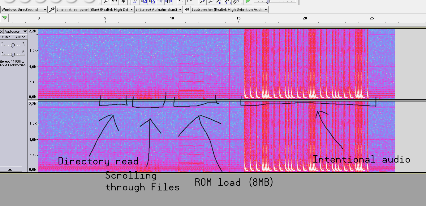
The SD noise isn't so terribly audible against the background noise from inside the PC, but just imagine that isn't there.
So you think the shared inductors resonate with the interference and that induces the same noise onto the other rails powered through it?
Totally agree!
As for the circuit... you mentioned having the JonnyMac.... what happens to the noise if you put some low ohm value resistors between the Vxxx and GND pins located at the 1x12way headers around the breadboard?
Perhaps 10ohm to 30ohm range. Could try with one Vxx rail, and add a couple more if that seems to have little difference. (You could try adding resistors to all of them, except those you are using for power supply to other circuits such as the SD card).
The test is just about getting the load current up to ensure the switching regulator is running in PWM mode at full frequency, and not dropping into lower (audio range) frequency mode for improved efficiency at lower current.
ROM load is most notable with roughly 270 Hz as strongest tone, with both even and odd harmonics ... a sawtooth maybe.
The TDK link is about the inductor acting as a direct audio transducer, rather than injecting electrical noise into the line out.
I was thinking the same- sawtooth Inductor current, especially at low load.
If adding some load with external resistors helps, then a more permanent improvement could be to swap a setting resistor on the module; put that switcher into forced pwm mode. Less efficient for some apps, but could be an improvement (more predictable) for audio applications.
BTW.. The new revision that's in manufacturing this week has a new switcher that's set to PWM-only mode. Along with some other improvements, that would be worth getting for audio applications. I've yet to get one for testing, but it has an improved stack-up that we hope will allow for thermal chamber testing at higher operating speeds, and I'm interested to see the raw PSRAM performance too.
Tried loading V00 with 25ohm (4x 100 ohm in parallel), made no difference. If it was noise from the regulator being in some sort of low-power mode, wouldn't that make it go away during access?
The directory listing is actually louder to me (when I listen with headphones directly attached), but it's also higher pitched. It barely comes through on the recording.
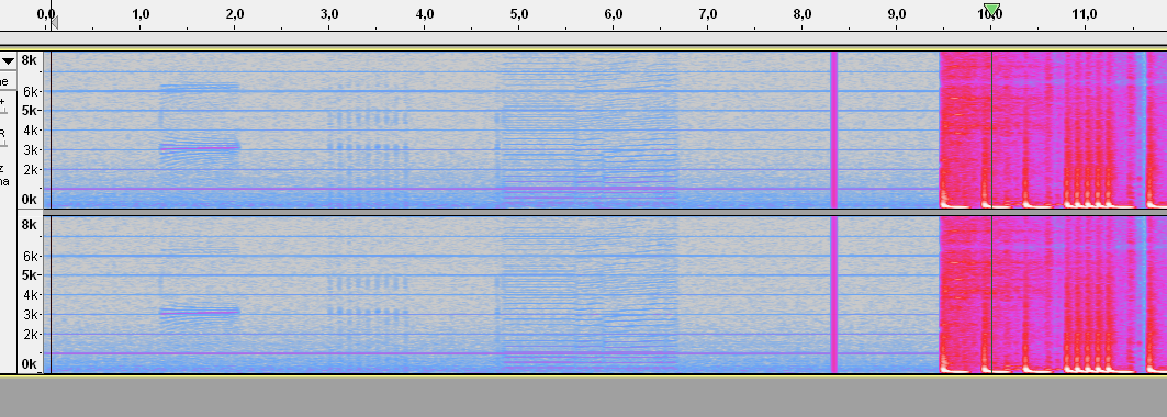
Pulled out the china special USB audio interface and tried it on that. A bit less noisy (lmao at those 1K harmonics though), so the spectrogram is a bit nicer:
I don't have the specs to hand, but it can be 1/4 or 1/2 load before they break a sweat. Sticking 10ohms on 2 or 3 of the V rails would assure that. Would be nice to be pulling 1amp.
Feels like running an SD and not much more wouldn't be getting much over 100mA on that ~4V switcher, regardless of what the other 1.8V switcher is doing.
What does your setup look like? Would that be something I could plug together etc.. to test it out (if that helps) ?
I guess you tried moving around the sound card to different headers ?
Looking at the JMac it has nice long parallel trace runs out to the far headers; probably audio best on P0xx with P8xx doing nothing (or asserted low).
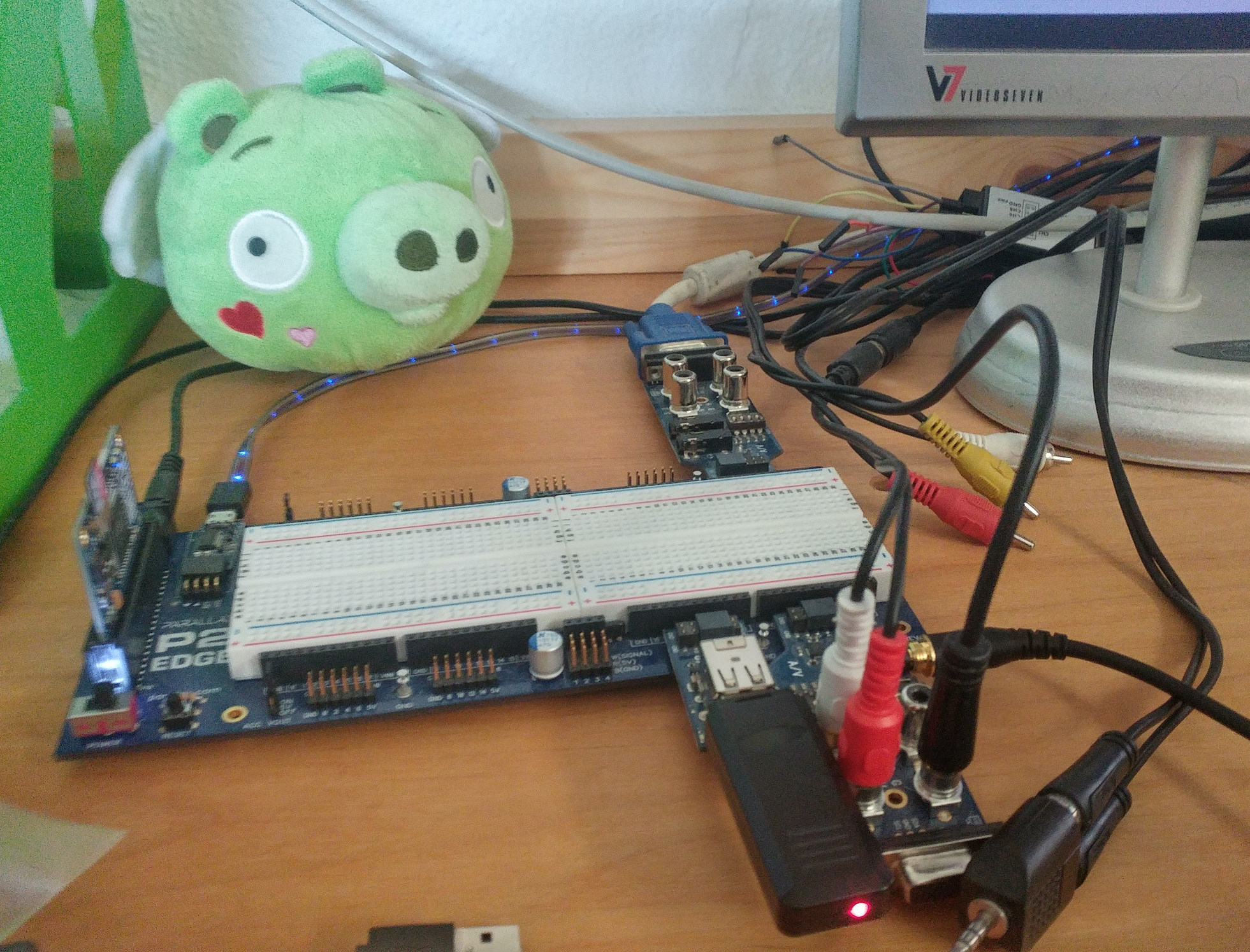
Yea, setup is just standard Parallax parts: P2EDGE-32MB (preproduction sample, IIRC) in a JohnnyMac, USB board on basepin 16 (with keyboard or gamepad connected to upper port), A/V board on basepin 24 with headphones connected (and the video jacks are also connected to my analog video capture card, but that's not really relevant I think), 2nd A/V board on basepin 32 with VGA connected. My SD card is a SanDisk Ultra 16GB. As mentioned above, SanDisk cards apparently cause the most interference of all the worthwhile brands, so it's probably best to use one of those.
As also mentioned, the test case I've been recording is MegaYume loading the big 8MB bad apple demo. The noise isn't actually an issue here, because the card isn't accessed during actual gameplay (unless SRAM needs to be flushed to disk, in which case it writes a 64K block). So if you want you can get the same code running, too (though your directory scan will be very short and you won't be able to really hear the little click that happens when you select a file unless you fill your directory with a lot of ROM files (can of course just be copies of the same one)).
Haven't tried that yet, but the SPI traces go on the other side of the board. There is potential for interaction with the USB though, IG, but that's not causing any (to me) audible noise.
I don't have that many 100 ohm resistors to put in parallel >.<
Here's a picture, too, not that it's really needed (I forgot to mention that a pig is an important part of the setup)
Wow.
(Just running the demo...)
Still, Wow..
How does it vary with different pin groups ?
One thing you could try, is to flip to differential mono, ie you feed inverted analog into L and non-inverted into R and listed L-R with no gnd connected.
That gives crude common ground rejection, so could give some clues as to the source(s) of crosstalk noise.
IIRC Cluso had a P2 board variant that was linear-only regulators, that would give another reference test point ?
Oh goodie, I can replicate the noise too. Doesn't sound like the switcher is involved. More like something polluting common ground after the LDO. Need to get on the bench and trace the source.
hmm. Does the code allow for driving the clk pin with lower drive strength?
As the new module might only be a week away, I'll leave this hardware setup and work through this with the new hardware before it starts shipping. Will report back here!
Just tried moving to P0; no obvious difference.") .
.
I've not tried an alternative breakout board yet. Something that doesn't dangle a long trace on the SD card CLK line. ( in fact, all SPI lines
Signal reflections across the extra breakout board are not controlled in any way.
I think you're right, although I don't have one of those. ManAtWork sent me one of his boards- I'll give that a try. I think it has a switching 1v8, but the layout is quite different so worth a comparison. The traces run direct to either side- should be about as short and direct as possible.
Yea, sure. The SD library is in the flexspin install directory,
include/filesys/fatfs/sdmm.cc. Pin setup starts on line 549.Ken and Chip have two of my boards (one with Flash, one without IIRC)
If you're planning on slowing things down to work with a weaker drive, then you'll want to retain the phase arrangement and lag compensation used during init. Meaning the later mode changes at line 638/639 would be best commented out. ie:
After that you can happily set something larger in the initial pin mode lines that Ada pointed to and they'll stick for the whole driver. eg:
ck_div = 0x0010_0020; // sysclock/32 ... _pinstart( PIN_CLK, spm_ck | P_SYNC_IO | P_HIGH_1K5 | P_LOW_1K5, ck_div, 0 ); ... _pinstart( PIN_DI, spm_tx | P_SYNC_IO | P_HIGH_1K5 | P_LOW_1K5, 31, -1 );Ah, good test of the SD connector layout - On the Eval Board revB, pin drive strength of 1500 ohms can't quite make 8 MHz SPI clock. 7.5 MHz works.
Did you ever tried clocking with any of the current-limited drive modes yet?
IIRC, some SD card specs show 100 uA PP-drive as an option when toggling their Dat0/MISO pins, while others are able to provide up to 1 mA at the same pin.
That was me testing 1500 ohm right then. EDIT: Oh, I see, the 1 mA mode won't be much different than the 1500 ohm mode. bitDAC will be a good in-between option though. EDIT3: Err, bitDAC isn't compatible with logic inputs for the smartpins.
But I'll be very interested in how 1500 ohms plays out first.
EDIT2: I stand corrected, 1 mA is notably weaker than 1500 ohms. Good for only 5.5 MHz SPI clock.
Just to be sure I'm understanding it right: I was thinking about something similar to a push-pull driver, thus, e.g., 1 mA PP means HHH="100" AND LLL="100"; any "high level" seen by the pin would result from the internal pull-up (inside the SD card).
Any amount of stray capacitance (including both sides (pins) and lane) would be appropriatelly charged/drainned, as commanded by P2.
In case SD card is absent, or its internal structure is open-faulty, the voltage level would self-center to ~Vio/2.
yes, just like above, eg:
_pinstart( PIN_CLK, spm_ck | P_SYNC_IO | P_HIGH_1MA | P_LOW_1MA, ck_div, 0 );PS: Variables are:
ck_div = 0x0010_0020; // sysclock/32 spm_ck = P_PULSE | P_OE | P_INVERT_OUTPUT | P_SCHMITT_A; // CPOL = 1 (SPI mode 3)Thanks for the clarification, @evanh.
I was also trying to understand if the same role (charge/discharging of lanes/nodes) could be played by a pin programmed as an input, e.g. P2_IO58 towards SD_DAT0/MISO (passing thru R304 (240R)), hence the striked-thru text, at the end of my last post.
I don't think the P2's SPI drive is the issue though - otherwise you'd hear everything going on all the other pins and that's not the case. (Notably, PSRAM is entirely quiet AFAICT)