@jmg said:
Thanks, so that could wobble about the finer details of timing based on align, but it should never be MHz paranoid.
Right.
If RossH can fit code into COG and see the same effect, that excludes any FIFO - HUB effects ?
A little more nuanced when it comes to my earlier example. Pure cogexec may not suit and hubexec branches can be beneficial for retaining a SPI phasing. But, yeah, far from ideal to rely on a particular incidence like that.
also is there a branch or end-of-rep block immediately after those two instructions? (is the second instruction the last of a block thats under a rep instruction) ?
@Tubular said:
Ross, back on the "mov a,b" example, is A or B a special register in those top 16 or so (eg INx, OUTx, DIRx etc)?
@Tubular said:
also is there a branch or end-of-rep block immediately after those two instructions? (is the second instruction the last of a block thats under a rep instruction) ?
No to both. They are just instructions in a stream of similar ordinary instructions.
I am still investigating the theory that somewhere else in the code is a pointer that points to this instruction, and so it is the value here that is affecting code elsewhere in unexpected ways. Someone suggested this earlier, but in fact I had already investigated this possibility and not found any uninitialized pointers or pointers with suspicious values. However I cannot completely rule it out, so I will continue investigating this one.
On the timing issue, I am going to combine a couple of the suggestions made yesterday. I was thinking about this problem again last night and it seems to me that since there is only one cog executing code from Hub RAM, with the other cogs all executing entirely within their own Cog RAM except when triggered by the main cog, this means that once the program and data have been loaded and all the other cogs are idle, the program should be completely deterministic. So I am going to start the program at a clock speed that is known to work, and patch in a change of clock speed to 180Mhz just after the SD card cog has finished doing its thing. After that point there is nothing in the program that should be affected by clock speed (the serial cog is only used after the failure has been detected) so if it doesn't fail then it must be an SD card problem that only shows up at a specific frequency.
180MHz is the 9th harmonic of 20MHz. But you've tested at the 5th, 11th, and 15th harmonics successfully.
What board are you using? It's possible that there is some resonance in the bypass capacitors at 180Mhz. But the window of non-working frequencies seems a bit small for this. Maybe it happens in combination with the clock harmonic.
I don't know if this is possible failure mode for semiconductors, but if you could test on a different chip that would be interesting. Or it could be an issue with a power pin not soldered or something. It seems like it's not the SD card, but if other paths don't yield a fix try a different brand or model of SD card.
@SaucySoliton said:
180MHz is the 9th harmonic of 20MHz. But you've tested at the 5th, 11th, and 15th harmonics successfully.
What board are you using? It's possible that there is some resonance in the bypass capacitors at 180Mhz. But the window of non-working frequencies seems a bit small for this. Maybe it happens in combination with the clock harmonic.
I don't know if this is possible failure mode for semiconductors, but if you could test on a different chip that would be interesting. Or it could be an issue with a power pin not soldered or something. It seems like it's not the SD card, but if other paths don't yield a fix try a different brand or model of SD card.
I am using Parallax P2 Evaluation boards. I've tried different sizes, speeds and brands of SD card, and also different Propeller chips - an original RevA board/chip and a RevB board/chip. Same repeatable failure occurs in all cases. This makes me think it is not a peripheral (i.e. SD Card) hardware problem, although it could still be an SD Card driver problem. My next tests should tell me whether that is the case.
It is either a slightly peculiar software bug (which is far and away the most likely scenario) or else a Propeller Hub/Cog interaction problem that only occurs in a narrow range of clock frequencies (which is highly unlikely given that it occurs around 180Mhz, which I would have thought was one of the most common frequencies for Propellers to use, so others would also have seen it by now).
According to my current understanding, you're using at least two P2-EVAL boards; one of RevA-series, and at least one of RevB-series.
In all cases, are you relying on the same "normal" USB cable to bring both power and data connection between your PC and the DUT, or did you also tried any of the available "heavy"-current power input methods?
Interesting idea. I actually have three P2 Evaluation boards - two RevA and one RevB. I was using the same cable for all tests, but I have just tried a couple of other cables, and I have also just tried powering the boards from the AUX USB port using a separate 2A USB supply. No difference.
Thanks for considering and testing for that possibility.
Another check could be ensuring that there are no sudden current consumption surges associated with the events of Micro SD card failure.
At least on RevB eval boards that check can be easyed due the presence of suitable Current Test Points: (J701) for Common_VDD, and (J901) for Common_LDOin, though I was'nt able to find any means of isolating the testing of Common_VIO, which powers the Micro SD and the SPI Flash (perhaps it's only my poor eyesight, playing a bit fuzzy with me).
RevA boards have (J602) for Common_VDD, and (J702) for Common_VIO.
@RossH said:
Interesting idea. I actually have three P2 Evaluation boards - two RevA and one RevB. I was using the same cable for all tests, but I have just tried a couple of other cables, and I have also just tried powering the boards from the AUX USB port using a separate 2A USB supply. No difference.
Is the failure the same on all 3 ? Does it fail directly out of reset ?
With 3 board, you could look for the bandwidth of the failure, if all fail at 180.00MHz ? what about 0.5MHz either side of that ? or 0.25MHz ?
I think Chip said the PLL 'works' with PFD below 1MHz, (was it to ~ 100kHz?) but just gets more jitter. You could enable a pin to check the actual MHz
With 3 chips and no temperature effect, this really is not sounding like a silicon issue, per se. I'd expect variations with chip and temperature.
What else is in your system, that is MHz exact ?
If you have a P2D2, you could reload the Si5351 with values for a more deterministic test ?
@RossH said:
... since there is only one cog executing code from Hub RAM, with the other cogs all executing entirely within their own Cog RAM except when triggered by the main cog, this means that once the program and data have been loaded and all the other cogs are idle, the program should be completely deterministic.
Do all COGS fail ?
Maybe Ken should send you a P2 Edge too ?
Addit: I think from rereading, it is just HUB code / HUB RAM that has issues ?
I assume those COG-Code only are polling memory, did you try one-hot-bit coding of shared memory flags, as this is more tolerant of (possible?) same-clk write/read issues.
If you pass pointers, you could keep a local copy, and add a wait-until-same to 'debounce' possible same-clk issues.
It seems like it's almost certainly something interacting with hardware (like the SD card) outside of the P2. Inside the P2 everything should be in sync and work on clock ticks, regardless of clock frequency. While it's true that there could be a P2 hardware bug that affects just one frequency, it seems extraordinarily unlikely that this would be at 180 MHz, which is the frequency the P2 was validated to work at!
I sat down today to try my latest tests on these two versions of the same program, one of which reliably failed and the other which reliably worked. I didn't even get to first base. Before starting the tests, I thought I had better baseline the behavior of both versions again. But both versions now behave exactly the same way - they both now reliably fail.
These are the same binaries, that (correctly) differ only in two longs, and I checked that they both recompile correctly from their respective source. I am using the same SD card, the the same board, and I have power cycled and reset the board and even cleaned and re-seated the SD card. I also tried different SD cards and also reformatting the SD cards. Same results.
Blast!, I thought. I bet I have damaged this particular board by messing about with power supplies and the AUX USB port yesterday. So I tried another board that I had not messed about with. Same results.
I have verified yet again that the program works at any speed other than 180Mhz. Interestingly, the 360Mhz version also works now, which did not work the last time I tested it (it wouldn't run at all). For those who think this may be temperature related, I can confirm that today is a cooler day than yesterday. But could a few degrees (maybe 5 degrees Celsius) make such a difference?
Clearly these are more clues, and they should tell me something. But other than the fact that the situation is a lot more fragile than I thought, I have no idea what
I have spent way too much time on this. I think I am going to simply change the default clock speed and move on until I get a more robust example of failure - preferably one in code that I can more easily share.
Since I don't want to slow any software down, I am thinking of making the default 200Mhz. Anyone have any other suggestions?
@RossH said:
But both versions now behave exactly the same way - they both now reliably fail.
That could be a good thing ?
I have verified yet again that the program works at any speed other than 180Mhz. Interestingly, the 360Mhz version also works now, which did not work the last time I tested it (it wouldn't run at all). For those who think this may be temperature related, I can confirm that today is a cooler day than yesterday. But could a few degrees (maybe 5 degrees Celsius) make such a difference?
Maybe.
Is the failure immediate ? Is it easy to check and restart after failure ?
You could check what PFD is a useful minimum, (1MHz, 500kHz, 250kHz?) and then set up an overnight run that sweeps finely across a wide MHz range and log for failures.
There may be other MHz than 180 where it also fails - it may be just a fluke you hit that one.
I like triangle Up/Down/up... tests, as they approach from a different direction, and a down sweep will be slightly warmer than a up sweep.
@jmg said:
You could check what PFD is a useful minimum, (1MHz, 500kHz, 250kHz?) and then set up an overnight run that sweeps finely across a wide MHz range and log for failures.
There may be other MHz than 180 where it also fails - it may be just a fluke you hit that one.
If I found other frequencies at which it fails, what would this tell me?
It can give useful information
It can confirm your alternate 200MHz choice is likely to be safe.
It can reveal if the issue behaves like the delays-vs-clock issues around P2 pins and fast memory like Hyperram.
FWIR, that effect has multiple good and bad zones, from < 100MHz to 300+MHz - with off-chip memory and multiple pins in play, those zones are broader than you report.
Definitely no P2 expert here, but which P2 board are you using, and how are you powering it?
I ask this, because I've had weird behavioral issues powering the P1 FLiP module from a USB source, which I've been able to eliminate by making a change to the USB chip's firmware.
@jmg said:
It can reveal if the issue behaves like the delays-vs-clock issues around P2 pins and fast memory like Hyperram.
FWIR, that effect has multiple good and bad zones, from < 100MHz to 300+MHz - with off-chip memory and multiple pins in play, those zones are broader than you report.
When I have an example of this failure that is easier to work with and which I can share, then I will do further investigation. All I need at the moment is for programs compiled with Catalina to run reliably, and all that requires is the use of a clock speed other than 180Mhz.
I will change the default, and also add a note about clock speeds to the next release.
Definitely no P2 expert here, but which P2 board are you using, and how are you powering it?
I ask this, because I've had weird behavioral issues powering the P1 FLiP module from a USB source, which I've been able to eliminate by making a change to the USB chip's firmware.
-Phil
I am using P2 Evaluation boards. I have RevA and RevB boards. I have tried powering them from both USB ports, and also both from the PC and an external 2A USB supply. The problem doesn't appear to be related to the power supply.
I will look into acquiring a P2 EDGE. I believe you can now buy the revC version from places that have reasonable shipping costs.
I am using P2 Evaluation boards. I have RevA and RevB boards. I have tried powering them from both USB ports, and also both from the PC and an external 2A USB supply. The problem doesn't appear to be related to the power supply.
Looking at the schematic, I have to agree. The external 2A supply does not involve an FTDI part.
I have now a "nop" problem with the "softsynth" audio driver I am writing now.
It worked, then I added 2 new instruction to the loop and it stopped working. Then adding a nop, or anything anywhere in the loop - makes it working again. This is very hard to debug and find why, because it is enough to set "debug enabled" in the compiler to make the loop work again, while adding wrlong variable to the hub is also adding the instruction and the loop works again. Very annoying thing. The loop is controled by waitse1, triggered by empty DAC. The loop has stiill some time to wait (DAC sample rate is 4096, the loop time is about 3700 clocks, of course adding the time measuring to the loop enabled it again.
@RossH said:
I have verified yet again that the program works at any speed other than 180Mhz. Interestingly, the 360Mhz version also works now, which did not work the last time I tested it (it wouldn't run at all). For those who think this may be temperature related, I can confirm that today is a cooler day than yesterday. But could a few degrees (maybe 5 degrees Celsius) make such a difference?
The Prop2 will self-limit the PLL's VCO freq below 360 MHz if the die gets warm enough. At which point I wouldn't trust the Prop2 to be 100% reliable. The higher the ambient is the more likely of tripping on this. And is a different issue from the bug at 180 MHz.
@pik33 said:
I have now a "nop" problem with the "softsynth" audio driver I am writing now.
It worked, then I added 2 new instruction to the loop and it stopped working. Then adding a nop, or anything anywhere in the loop - makes it working again. This is very hard to debug and find why, because it is enough to set "debug enabled" in the compiler to make the loop work again, while adding wrlong variable to the hub is also adding the instruction and the loop works again. Very annoying thing. The loop is controled by waitse1, triggered by empty DAC. The loop has stiill some time to wait (DAC sample rate is 4096, the loop time is about 3700 clocks, of course adding the time measuring to the loop enabled it again.
How does that react to changes in MHz ?
If you keep adding "nop" is there a count(s) where it works again ?
If you add nops outside the loop (ie just slide in memory) is the effect the same ?
How does that react to changes in MHz ?
If you keep adding "nop" is there a count(s) where it works again ?
If you add nops outside the loop (ie just slide in memory) is the effect the same ?
Please note that, by just adding more (and more) NOP's, beyond enlarging code size, will also extend its execution time in a two-clock-per-step-wise way, which can lead to "skip", or "miss", any eventual odd-count-increase-related weirdness.
WAITX {#}D {WC/WZ/WCZ} can be a dependable (and also code-size-conscious) way of testing any other eventual point(s) of interest, from three(TWO, in fact), and beyond.
How does that react to changes in MHz ?
If you keep adding "nop" is there a count(s) where it works again ?
If you add nops outside the loop (ie just slide in memory) is the effect the same ?
Please note that, by just adding more (and more) NOP's, beyond enlarging code size, will also extend its execution time in a two-clock-per-step-wise way, which can lead to "skip", or "miss", any eventual odd-count-increase-related weirdness.
WAITX {#}D {WC/WZ/WCZ} can be a dependable (and also code-size-conscious) way of testing any other eventual point(s) of interest, from three, and beyond.
Good idea, adding that too, allows coverage of both code-domain as I mentioned, and time-domain as you mention.
This effect is vague enough, we are not sure if it is code-domain or time-domain issue. ( or both, or neither )
How does that react to changes in MHz ?
If you keep adding "nop" is there a count(s) where it works again ?
If you add nops outside the loop (ie just slide in memory) is the effect the same ?
Please note that, by just adding more (and more) NOP's, beyond enlarging code size, will also extend its execution time in a two-clock-per-step-wise way, which can lead to "skip", or "miss", any eventual odd-count-increase-related weirdness.
WAITX {#}D {WC/WZ/WCZ} can be a dependable (and also code-size-conscious) way of testing any other eventual point(s) of interest, from three (TWO, in fact, see the PS), and beyond.
Good idea, adding that too, allows coverage of both code-domain as I mentioned, and time-domain as you mention.
This effect is vague enough, we are not sure if it is code-domain or time-domain issue. ( or both, or neither )
PS I just noticed a misconception was left buried into my post, but, since you've quoted on it, I can't just repair it (as it happened), without affecting your own.
I beg your excuses for someway mistakenly reading the docs (on behalf of my own sanity, I was trying to make some fresh coffee, and ensure the english translation went clear enough, at the same time, but the fluke ever strikes, anyway)!
Just a thought, but were any of the FPGA P2 models close enough to perhaps be usefull to see if the problem can be replicated on one of them? Another thought on this, could the pipeline methods of the P2 be part of what is going on?
@RossH said:
I have verified yet again that the program works at any speed other than 180Mhz. Interestingly, the 360Mhz version also works now, which did not work the last time I tested it (it wouldn't run at all). For those who think this may be temperature related, I can confirm that today is a cooler day than yesterday. But could a few degrees (maybe 5 degrees Celsius) make such a difference?
The Prop2 will self-limit the PLL's VCO freq below 360 MHz if the die gets warm enough. At which point I wouldn't trust the Prop2 to be 100% reliable. The higher the ambient is the more likely of tripping on this. And is a different issue from the bug at 180 MHz.
How warm is "warm enough"? I have some evidence that this issue is somehow temperature related, but it is not yet clear cut enough to be conclusive.
For instance, yesterday I could get the failing program to work about 75% of the time. Today it is a colder morning and it won't work at all. I have tried warming the board up a little, but no change yet. I will try warming it some more, but I have a hard time believing that an ambient temperature change of only about 5 degrees (say from 20 degrees C yesterday down to 15 degrees C today) would make that much difference.
I also tried putting the board in the freezer for a while yesterday, which did seem to make a difference - it wouldn't work till it warmed up, then it began to work quite reliably for a while.
So - how much temperature change should be necessary to change the Props behaviour? And does it make any sense that it seems to work better when is warmer?
We did a fair bit of 'pll wobble hunting' on the Rev A silicon, and yes a few degrees can make a difference. We used a lamp to gently illuminate the P2. A lot our out tests were around the 47~55 C surface temperature area, where the first signs were detectable. This got fixed in the rev B and C silicon, but I note you are still using some Rev A boards. There was a pattern to the onset and receding of the effects that was quite reproducable, and the gentle lamp enable this to be transitioned and reversed slowly.
For that testing we were observing the effects on Roger's very high res Sony CRT, and while the effects were visible on VGA video, we didn't really dive into what the effects would be on other internal and external aspects of the P2, eg would the HDMI absorb these jitters? High speed serial? Memory interfaces?
You're right in that warmer would generally be better, but it depends on the mechanism in play - and at this stage you're probably just looking to get something reliably reproduceable. Let us know if we can help - there's still plenty of Rev A and other hardware around from those tests.
@RossH said:
How warm is "warm enough"? I have some evidence that this issue is somehow temperature related, but it is not yet clear cut enough to be conclusive.
For instance, yesterday I could get the failing program to work about 75% of the time. Today it is a colder morning and it won't work at all. I have tried warming the board up a little, but no change yet. I will try warming it some more, but I have a hard time believing that an ambient temperature change of only about 5 degrees (say from 20 degrees C yesterday down to 15 degrees C today) would make that much difference.
I also tried putting the board in the freezer for a while yesterday, which did seem to make a difference - it wouldn't work till it warmed up, then it began to work quite reliably for a while.
So - how much temperature change should be necessary to change the Props behaviour? And does it make any sense that it seems to work better when is warmer?
Since you seem to have notch behaviour, (where narrow bands fail but most work), then yes, small temperatures changes could move that notch left or right by enough.
You may also find a program that 'was working', breaks at more extreme temperatures.
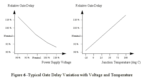
I found this
shows that 5°C is about 1%, or almost 2MHz of equivalent clock movement at 200MHz


Comments
Right.
A little more nuanced when it comes to my earlier example. Pure cogexec may not suit and hubexec branches can be beneficial for retaining a SPI phasing. But, yeah, far from ideal to rely on a particular incidence like that.
Ross, back on the "mov a,b" example, is A or B a special register in those top 16 or so (eg INx, OUTx, DIRx etc)?
also is there a branch or end-of-rep block immediately after those two instructions? (is the second instruction the last of a block thats under a rep instruction) ?
No to both. They are just instructions in a stream of similar ordinary instructions.
I am still investigating the theory that somewhere else in the code is a pointer that points to this instruction, and so it is the value here that is affecting code elsewhere in unexpected ways. Someone suggested this earlier, but in fact I had already investigated this possibility and not found any uninitialized pointers or pointers with suspicious values. However I cannot completely rule it out, so I will continue investigating this one.
On the timing issue, I am going to combine a couple of the suggestions made yesterday. I was thinking about this problem again last night and it seems to me that since there is only one cog executing code from Hub RAM, with the other cogs all executing entirely within their own Cog RAM except when triggered by the main cog, this means that once the program and data have been loaded and all the other cogs are idle, the program should be completely deterministic. So I am going to start the program at a clock speed that is known to work, and patch in a change of clock speed to 180Mhz just after the SD card cog has finished doing its thing. After that point there is nothing in the program that should be affected by clock speed (the serial cog is only used after the failure has been detected) so if it doesn't fail then it must be an SD card problem that only shows up at a specific frequency.
Which would be a relief!")
180MHz is the 9th harmonic of 20MHz. But you've tested at the 5th, 11th, and 15th harmonics successfully.
What board are you using? It's possible that there is some resonance in the bypass capacitors at 180Mhz. But the window of non-working frequencies seems a bit small for this. Maybe it happens in combination with the clock harmonic.
I don't know if this is possible failure mode for semiconductors, but if you could test on a different chip that would be interesting. Or it could be an issue with a power pin not soldered or something. It seems like it's not the SD card, but if other paths don't yield a fix try a different brand or model of SD card.
I am using Parallax P2 Evaluation boards. I've tried different sizes, speeds and brands of SD card, and also different Propeller chips - an original RevA board/chip and a RevB board/chip. Same repeatable failure occurs in all cases. This makes me think it is not a peripheral (i.e. SD Card) hardware problem, although it could still be an SD Card driver problem. My next tests should tell me whether that is the case.
It is either a slightly peculiar software bug (which is far and away the most likely scenario) or else a Propeller Hub/Cog interaction problem that only occurs in a narrow range of clock frequencies (which is highly unlikely given that it occurs around 180Mhz, which I would have thought was one of the most common frequencies for Propellers to use, so others would also have seen it by now).
According to my current understanding, you're using at least two P2-EVAL boards; one of RevA-series, and at least one of RevB-series.
In all cases, are you relying on the same "normal" USB cable to bring both power and data connection between your PC and the DUT, or did you also tried any of the available "heavy"-current power input methods?
Interesting idea. I actually have three P2 Evaluation boards - two RevA and one RevB. I was using the same cable for all tests, but I have just tried a couple of other cables, and I have also just tried powering the boards from the AUX USB port using a separate 2A USB supply. No difference.
Thanks for considering and testing for that possibility.
Another check could be ensuring that there are no sudden current consumption surges associated with the events of Micro SD card failure.
At least on RevB eval boards that check can be easyed due the presence of suitable Current Test Points: (J701) for Common_VDD, and (J901) for Common_LDOin, though I was'nt able to find any means of isolating the testing of Common_VIO, which powers the Micro SD and the SPI Flash (perhaps it's only my poor eyesight, playing a bit fuzzy with me).
RevA boards have (J602) for Common_VDD, and (J702) for Common_VIO.
Is the failure the same on all 3 ? Does it fail directly out of reset ?
With 3 board, you could look for the bandwidth of the failure, if all fail at 180.00MHz ? what about 0.5MHz either side of that ? or 0.25MHz ?
I think Chip said the PLL 'works' with PFD below 1MHz, (was it to ~ 100kHz?) but just gets more jitter. You could enable a pin to check the actual MHz
With 3 chips and no temperature effect, this really is not sounding like a silicon issue, per se. I'd expect variations with chip and temperature.
What else is in your system, that is MHz exact ?
If you have a P2D2, you could reload the Si5351 with values for a more deterministic test ?
Do all COGS fail ?
Maybe Ken should send you a P2 Edge too ?
Addit: I think from rereading, it is just HUB code / HUB RAM that has issues ?
I assume those COG-Code only are polling memory, did you try one-hot-bit coding of shared memory flags, as this is more tolerant of (possible?) same-clk write/read issues.
If you pass pointers, you could keep a local copy, and add a wait-until-same to 'debounce' possible same-clk issues.
It seems like it's almost certainly something interacting with hardware (like the SD card) outside of the P2. Inside the P2 everything should be in sync and work on clock ticks, regardless of clock frequency. While it's true that there could be a P2 hardware bug that affects just one frequency, it seems extraordinarily unlikely that this would be at 180 MHz, which is the frequency the P2 was validated to work at!
This is doing my head in!
I sat down today to try my latest tests on these two versions of the same program, one of which reliably failed and the other which reliably worked. I didn't even get to first base. Before starting the tests, I thought I had better baseline the behavior of both versions again. But both versions now behave exactly the same way - they both now reliably fail.
These are the same binaries, that (correctly) differ only in two longs, and I checked that they both recompile correctly from their respective source. I am using the same SD card, the the same board, and I have power cycled and reset the board and even cleaned and re-seated the SD card. I also tried different SD cards and also reformatting the SD cards. Same results.
Blast!, I thought. I bet I have damaged this particular board by messing about with power supplies and the AUX USB port yesterday. So I tried another board that I had not messed about with. Same results.
I have verified yet again that the program works at any speed other than 180Mhz. Interestingly, the 360Mhz version also works now, which did not work the last time I tested it (it wouldn't run at all). For those who think this may be temperature related, I can confirm that today is a cooler day than yesterday. But could a few degrees (maybe 5 degrees Celsius) make such a difference?
Clearly these are more clues, and they should tell me something. But other than the fact that the situation is a lot more fragile than I thought, I have no idea what
I have spent way too much time on this. I think I am going to simply change the default clock speed and move on until I get a more robust example of failure - preferably one in code that I can more easily share.
Since I don't want to slow any software down, I am thinking of making the default 200Mhz. Anyone have any other suggestions?
Ross.
I never did get my P2D2. I thought they were never actually produced.
That could be a good thing ?")
Maybe.
Is the failure immediate ? Is it easy to check and restart after failure ?
You could check what PFD is a useful minimum, (1MHz, 500kHz, 250kHz?) and then set up an overnight run that sweeps finely across a wide MHz range and log for failures.
There may be other MHz than 180 where it also fails - it may be just a fluke you hit that one.
I like triangle Up/Down/up... tests, as they approach from a different direction, and a down sweep will be slightly warmer than a up sweep.
If I found other frequencies at which it fails, what would this tell me?
It can give useful information
It can confirm your alternate 200MHz choice is likely to be safe.
It can reveal if the issue behaves like the delays-vs-clock issues around P2 pins and fast memory like Hyperram.
FWIR, that effect has multiple good and bad zones, from < 100MHz to 300+MHz - with off-chip memory and multiple pins in play, those zones are broader than you report.
@RossH,
Definitely no P2 expert here, but which P2 board are you using, and how are you powering it?
I ask this, because I've had weird behavioral issues powering the P1 FLiP module from a USB source, which I've been able to eliminate by making a change to the USB chip's firmware.
-Phil
When I have an example of this failure that is easier to work with and which I can share, then I will do further investigation. All I need at the moment is for programs compiled with Catalina to run reliably, and all that requires is the use of a clock speed other than 180Mhz.
I will change the default, and also add a note about clock speeds to the next release.
I am using P2 Evaluation boards. I have RevA and RevB boards. I have tried powering them from both USB ports, and also both from the PC and an external 2A USB supply. The problem doesn't appear to be related to the power supply.
I will look into acquiring a P2 EDGE. I believe you can now buy the revC version from places that have reasonable shipping costs.
Looking at the schematic, I have to agree. The external 2A supply does not involve an FTDI part.
-Phil
I have now a "nop" problem with the "softsynth" audio driver I am writing now.
It worked, then I added 2 new instruction to the loop and it stopped working. Then adding a nop, or anything anywhere in the loop - makes it working again. This is very hard to debug and find why, because it is enough to set "debug enabled" in the compiler to make the loop work again, while adding wrlong variable to the hub is also adding the instruction and the loop works again. Very annoying thing. The loop is controled by waitse1, triggered by empty DAC. The loop has stiill some time to wait (DAC sample rate is 4096, the loop time is about 3700 clocks, of course adding the time measuring to the loop enabled it again.
The Prop2 will self-limit the PLL's VCO freq below 360 MHz if the die gets warm enough. At which point I wouldn't trust the Prop2 to be 100% reliable. The higher the ambient is the more likely of tripping on this. And is a different issue from the bug at 180 MHz.
How does that react to changes in MHz ?
If you keep adding "nop" is there a count(s) where it works again ?
If you add nops outside the loop (ie just slide in memory) is the effect the same ?
Please note that, by just adding more (and more) NOP's, beyond enlarging code size, will also extend its execution time in a two-clock-per-step-wise way, which can lead to "skip", or "miss", any eventual odd-count-increase-related weirdness.
WAITX {#}D {WC/WZ/WCZ} can be a dependable (and also code-size-conscious) way of testing any other eventual point(s) of interest, from three (TWO, in fact), and beyond.
Good idea, adding that too, allows coverage of both code-domain as I mentioned, and time-domain as you mention.") )
)
This effect is vague enough, we are not sure if it is code-domain or time-domain issue. ( or both, or neither
PS I just noticed a misconception was left buried into my post, but, since you've quoted on it, I can't just repair it (as it happened), without affecting your own.
I beg your excuses for someway mistakenly reading the docs (on behalf of my own sanity, I was trying to make some fresh coffee, and ensure the english translation went clear enough, at the same time, but the fluke ever strikes, anyway)!
Just a thought, but were any of the FPGA P2 models close enough to perhaps be usefull to see if the problem can be replicated on one of them? Another thought on this, could the pipeline methods of the P2 be part of what is going on?
How warm is "warm enough"? I have some evidence that this issue is somehow temperature related, but it is not yet clear cut enough to be conclusive.
For instance, yesterday I could get the failing program to work about 75% of the time. Today it is a colder morning and it won't work at all. I have tried warming the board up a little, but no change yet. I will try warming it some more, but I have a hard time believing that an ambient temperature change of only about 5 degrees (say from 20 degrees C yesterday down to 15 degrees C today) would make that much difference.
I also tried putting the board in the freezer for a while yesterday, which did seem to make a difference - it wouldn't work till it warmed up, then it began to work quite reliably for a while.
So - how much temperature change should be necessary to change the Props behaviour? And does it make any sense that it seems to work better when is warmer?
We did a fair bit of 'pll wobble hunting' on the Rev A silicon, and yes a few degrees can make a difference. We used a lamp to gently illuminate the P2. A lot our out tests were around the 47~55 C surface temperature area, where the first signs were detectable. This got fixed in the rev B and C silicon, but I note you are still using some Rev A boards. There was a pattern to the onset and receding of the effects that was quite reproducable, and the gentle lamp enable this to be transitioned and reversed slowly.
For that testing we were observing the effects on Roger's very high res Sony CRT, and while the effects were visible on VGA video, we didn't really dive into what the effects would be on other internal and external aspects of the P2, eg would the HDMI absorb these jitters? High speed serial? Memory interfaces?
You're right in that warmer would generally be better, but it depends on the mechanism in play - and at this stage you're probably just looking to get something reliably reproduceable. Let us know if we can help - there's still plenty of Rev A and other hardware around from those tests.
Since you seem to have notch behaviour, (where narrow bands fail but most work), then yes, small temperatures changes could move that notch left or right by enough.
You may also find a program that 'was working', breaks at more extreme temperatures.
I found this
shows that 5°C is about 1%, or almost 2MHz of equivalent clock movement at 200MHz