

Industrial servo controller project (re-spin 22)
 ManAtWork
Posts: 2,334
ManAtWork
Posts: 2,334
I have started the original project more than two years ago. Then, COVID came and my time to do any serious P2 developments dropped to nearly zero. I'm about to slowly recover from that but the second problem is the current semiconductor crisis. Many components of my design (fortunatelly, not the Propeller itself) became unavailable and rendered the whole board obsolete. ![]()
I have to start all over, again. Instead of using highly specialized ICs like InAs hall effect current sensors I revert to more discrete analog circuitry. Simple shunt resistors for current measurement will be better available and if not I can carve them from bare metal. ![]()
So here is my draft for the new schematic. Part count rised dramatically compared to the old design but I think BOM cost will stay nearly the same. As I've already mentioned there will be two propellers. A P1 on the low voltage side and a P2 connected to the power stage which runs directly on rectified mains voltage. They communicate over a serial interface with isolated data couplers.
The P2 handles PWM for the power stage, current control, velocity and position PID loops and all analogue signal processing. The P1 takes care of the more low-level functions like GPIO, fan control, incremental encoder input and resolver feedback (which requires an external ADC anyway). Step/Dir input and the special QPSK encoder interface require isolation anyway and therefore can go to the P2 directly.
Comments
Hi
I 'think' you are going to need an opto-isolated reset from prop2 to prop 1 if the prop 2 is to supply the boot code.
Dave
@ManAtWork
I don't get the P1 for incremental encoders. Is it fast enough?
Feels like bicycle wheels on an F1 car. 🤔
Regards,
Craig
Don't worry. The P1 is fast enough for incremental encoders up to 1MHz count rate. It can also talk to SanyoDenki or Tamagawa absolute encoders over RS485 2.5MBd connection. However, it can't really support analogue sin/cos incremental encoders or EnDat. But I've never implemented that, so far. If I had to I'd add an extension board with external ADCs.
Connnecting the encoder feedback to the P2 side would require a lot more expensive optocouplers.
Yes, I already mentioned this in the "boot a P1" thread. I think I'll add an optocoupler for reset or a separate Progplug connector on the prototype board but leave it un-occupied on the series boards.
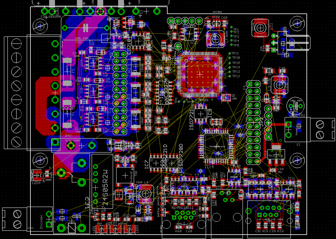
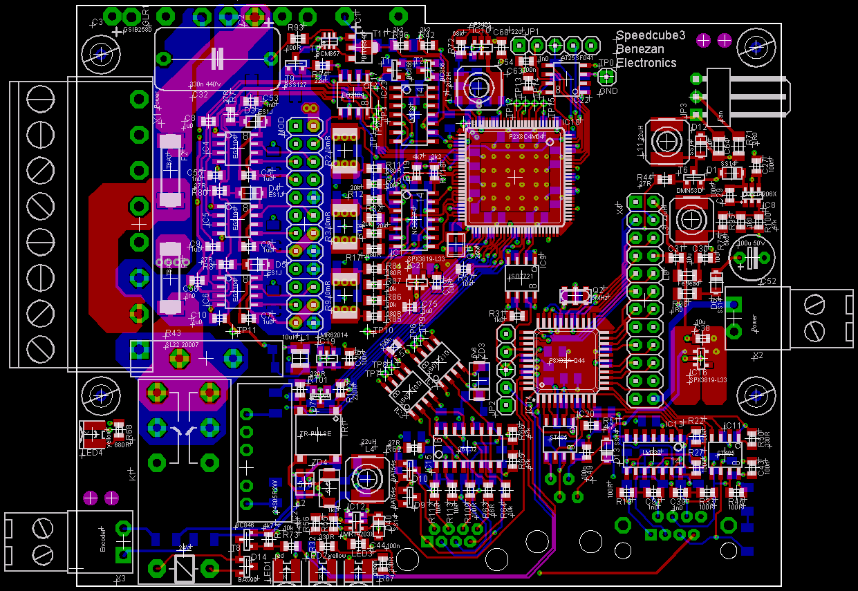
This is the first placement. The isolation barrier is runing zig-zag across the board and eats up a lot of space. Therefore a lot of components have to go on the bottom side. It's going to be tough but I think it should be possible to fit everything into the same case size as before.
What is the Soft Start relay for? Why not use an NTC?
An NTC needs to heat up to get low resistance. In servo applications you don't have a constant load all the time. If the motor stand still most of the time there's not enough current draw for the NTC to heat up. Then when you suddenly need power the resistance is too high. Second, there are often many drives in one machine. If all NTCs are hot it takes several minutes to cool down. So if you switch the machine off and instantly back on the fuse will blow becase all NTC have still low resistance.
Therefore I use an NTC plus a relay to short it. This is fail-safe because the resistor is self-limiting in the case the relay doesn't switch because of under-voltage.
I love puzzles. It's almost solved.
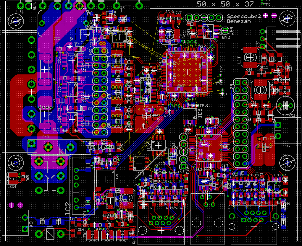
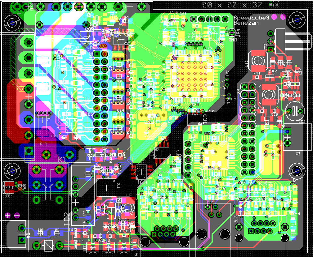
inner layers:
Done")
This was the first time in my life that turning a component by 45° was really handy. I also added a hardware comperator and a latch for overcurrent protection. Somehow I don't feel good relying on software for safety features.
Just a fyi as I've seen other German vfd designs stuck in UL limbo for years:
If you would ever want this design to be UL listed, overcurrent protection is required to be a fuse.
That fuse is required even if it should normally never blow because another hardware/software circuit triggers first.
Look at the big vertical rectangles near to the 8-way screw terminal on the left side marked "T6A" and "F1" and "F2". Theese fuses are in the AC path before the rectifier and should blow even if somebody fills up the drive with metal chips so that the electronic protection has no chance to switch off.
However, a customer recently managed to burn a drive without the fuse blowing. He connected a ballast resitor (for braking) with the wrong resistance. It had only 1.2 ohms instead of ~20 ohms. This caused an error current of >100A and melted the braking IGBT and discharged the DC bus to almost zero volts. This in turn caused the motor spinning at high RPM to act as generator, feeding an uncontrollable current back through the free wheeling diodes. This also melted the MOSFETs because theres no way to switch off the current when the DC bus voltage is lower than the back EMF of the motor.
The energy is limited by the kinetic energy stored in the rotor, though. It was high enough to completely destroy the power stage but was not enough to cause a serious fire.
My protection circuit monitors the current through the ground path of all three half bridges and the high side leg of the DC bus with hardware comperators. Overcurrent resets a latch which can only be set by an output pin high to low transition.
Being able to use all the pins of the propeller for any purpose is a big advantage. But it makes me a bit nervous when it comes to security because any cog can overwrite the state of any pin if it crashes. There is no "unknown instruction" exception like on the 68000 which could stop most of the software runaways. I've seen software crashes that caused random memory overwrites and wild pin toggeling. DIR=1 and OUT=1 takes over priority because they are all OR-wired together. So locking the pin for the power stage enable latch in a 1 state provides at least a bit of protection against accidental re-enabling after an error.
I've assembled two prototype boards.
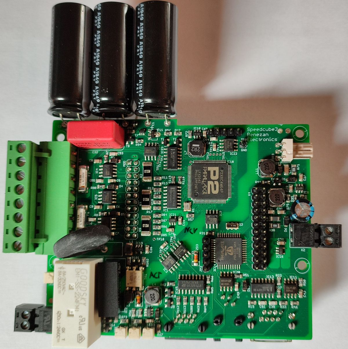
The isolation barrier between the power stage (230VAC) and the IO-side (24VDC) can be seen as slightly brighter line running from the lower left to the upper right corner. The P2 controls the power stage and the P1 handles all the IO. The "bridges" across the insulation barrier are (from left to right): soft start relay, DCDC-converter (24V to P2 power supply), pulse transformer (encoder data), two data couplers for command input (directly to the P2) and one coupler for P1-P2 communication. The big green terminal on the left is for all the power connections (mains, motor and bleed resistor), the smaller black on the left for the encoder (5V + QPSK data). The black terminal on the right is the 24VDC power supply. The 3-pin connector is for the cooling fan.
On the bottom side you can see the connectors for 3rd party encoders (incremental or RS485 absolute), PC programming and diagnosis serial interface and command input (step/dir or optionally SPI). The female header in the middle connects to the IGBT board for the power stage.
@ManAtWork
Nice job Nicolas I might become a customer. What is the spec' of the complete drive?
Green connector: Did you use a rip-off supplier or Aliexpress? I got some AE samples and the quality is second-to-none.
Currently I have qty-13 12-ways planned for my system; I realise that they are more of a power connector but I like the beefiness and so I'm using them for everything.
Regards,
Craig
There is no real spec, yet. The power stage can deliver up to 5A RMS continous current at 230V and 20A peak current. The hardware is capable of interfacing to several types of encoders. Resolvers can be read with an extension board. But which features are finally supported depens on the amount of work I can put into softare development.
It doesn't make much sense to sell the drive as general purpose servo. I hope I can build a closed loop stepper drive out of it that won't cost much more than the open loop stepper drives I currently use. One of my main customer needs around 300 drives per year. If I can convince him to buy the new drives that would justify investing more development time into more sophisticated features.
I bought them from LCSC. The manufacturer is called Ningbo Kangnex. They offer reasonable quality for a good price. Aliexpress? Well, "Ali Baba" is the name of a bandit from the 1001 nights fairy tales. So what do you expect... Sometimes you can be lucky and make a good deal. I got some milling cutters and tool holders of good quality, there. But recently I orderes some chips for >$800 and all I got was an empty blister envelope.
$800!!!! Ouch!!!
I've had nothing but 100% success
The real bandits are the likes of Siemens and Beckhoff. I can't believe how successfully they are brainwashing the industry.
I just want a simple BLDC drive without all of the Smile bells and whistles. But I'm in the 2KW to 5KW range.
Craig
Nicolas, I'll send you a PMSM with a resolver, so you can test. If it works nicely, I'll need about 25 boards.
@Mickster Fortunatelly, I got the money back after complaining. But all the trouble and delay (I had to wait for the empty envelope and then order elsewhere while the price was rising) was no fun at all.
2KW should be no problem. I could simply replace the IGBTs and the heatsink with bigger ones. But 5kW requires 400V 3-phase power and is a bit more complicated. What command signals do you need? step/dir is my current standard, but +/-10V should also be possible with an external ADC. Or if your master motion controller is also a P2 anyway then a serial protocol would be best.
@ErNa As I said, resolvers require a daughter board with an external ADC. The ADC chip is, of course, currently sold out worldwide but you are lucky. I have exactly 26 pieces in stock.")
@ManAtWork
I would've paid good money to see your face when you opened that envelope
Ah, been meaning to clarify this step/dir.....not to be confused with PWM/dir, correct?
IOW, step-count = command position and step-rate = command velocity?
This would mean that the PID would not be handled by my system which would be a problem for me.
I prefer commanding +/-10v because:
Regarding the resolver daughter board; this would be a cool standalone product if it could also do RTD (conversion to incremental encoder?)
Craig
With the smart pins of the P2 it would be no problem to change step/dir into PWM/dir and command torque instead of position. It would be actuially a lot easier for me as I could totally skip the PID control loops for position and velocity. No tuning required either. You probably generate the +/-10V signal anyway by PWM-to-analogue conversion or with a DAC pin and an OPA as level shifter. By using PWM/dir instead we could get rid of the OPA, ADC and drift/offset problems.
I'd just made an experiment: a LS75174 driven by a 40 kHz PWM generates the carrier (full bridge, push-pull) for a special lvdt transducer from Mitutoyo. The response signals amplitude pp is about 0.3V. Connected via a 10 nF cap to the input of a P1's simple adc I can get a readout of +- 200 counts, very noisy, but if I use an R/C-filter IIR the signal looks nice.
@ManAtWork
Great news I think we're on to something
Craig
Arrgggg! Spent several hours today to find out why the P1 can't be booted. I found out that the chinese version of the ISO7721 isolated coupler called CA-IS3721 has the input and output pins mirrored.
 There is a different version with compatible pinouts called CA-IS3722 but I don't have it and I don't want to wait for it. So I'll de-solder the wrong ones and re-solder them in upside-down.
I've additionally found two layout errors but those can be fixed with jumper wires.
"jumper wires"....doesn't that just pi$$ you off
It's like getting a ding in your brand new car....you just wanna throw it away and get another
Craig
That's why prototypes are built. If we all were perfect we could do it just right and start series production immediately. There would also be no need for a debugger. And any kind of research would be futile. You could just calculate the correct solution.
Ok, it works. With the flipped over CA-IS3721 I can successfully boot the P1 from the P2. The process is a bit complicated because I don't have a way to reset the P1 under control of the P2. So I have to either...
a) connect two ProgPlugs, one to the P1 and one to the P2 and download and test the two binaries seperately, or
b) program the P2 including the loader (code here) and then power-cycle both to make the P2 boot from Flash and immediately afterwards boot the P1 before it times out.
After correcting another mistake in the schematics I can drive the motor and get readings from the ADCs. Everything is still totally without calibration, synchronisation and only open-loop. But at least the hardware works. The next challange is to get as much as possible SNR out of the current measurement ADCs.
:-)
I've got the synchronization between the PWM and ADC pins sorted out. I need a minimum of 5% duty cycle @12kHz to get valid samples. The sampling period is 512 clocks with SINC3 filtering and only the last one or two bits are toggeling if I scale the resulty to 12 bits. This means the ENOB is 10 bits or better which should be enough for a smooth FOC. This is without any additional low pass filtering over multiple PWM periods.
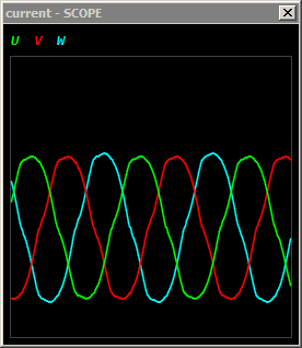
The distortion (imperfect sine waves) is caused by zero-crossing hysteresis due to dead time of the IGBT drivers and iron saturation effects in the motor. The channel mismatch is caused by the lack of gain and offset correction for the ADC pins. But there is very little random noise so I'm optimistic that I can trim the errors out.
Now, I can communicate between the P1 and P2. While 4MBd is rather boring for the P2 it is quite a challange for the P2, especially full duplex and with checksums. Same for debugging. I have two Progplugs attached to the board, one for the P1 and one for the P2 obviously. But as the P1 RX/TX boot pins are already connected to the serial port of the P2 I had to use different pins and use them in read only mode for debugging. The code for the P1 has to be compiled as binary and then included into the P2 software and then downloaded to the P2.
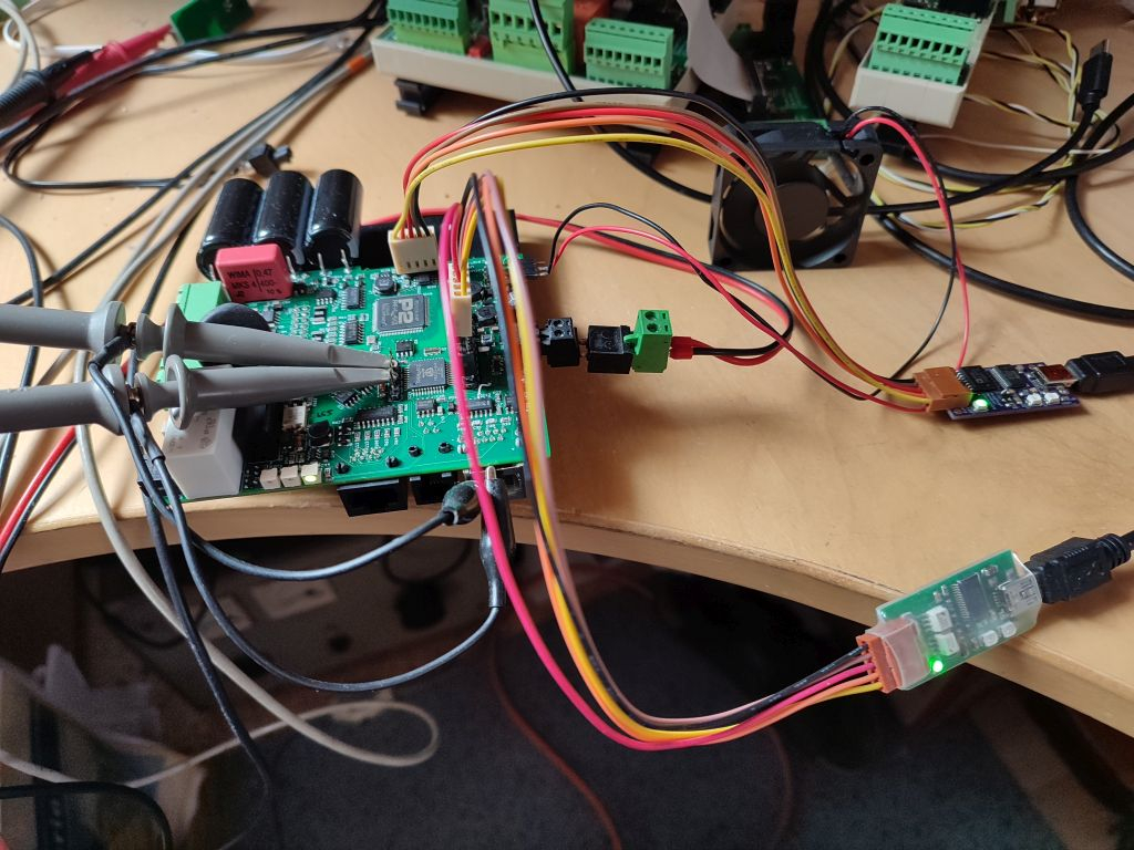
BTW, the cooling fan is also running, of course PWM speed controlled.