

FLiP needs longer legs
 Phil Pilgrim (PhiPi)
Posts: 23,514
Phil Pilgrim (PhiPi)
Posts: 23,514
I'm sure this is something the designers of my favorite Parallax product, the FLiP module, never thought of, but it's come to bite me. The FLiP works great when plugged into a normal receptacle. But I bought some reverse receptacles recently, so I could mount the FLiP from the bottom of the board to keep a low profile. The device I designed the FLiP into worked only sporadically. It was because the FLiP's legs weren't quite long enough to make reliable contact with the receptacle, given the extra 1/16" of board they had to reach through.
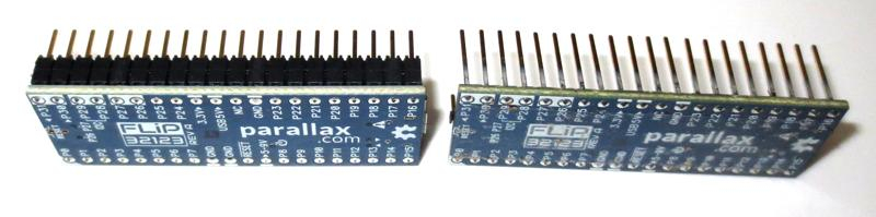
As a consequence, I had to remove the insulating spacers from the FLiP's two 20-pin headers to get it into the socket far enough:
Another 0.075" on the leg length would be enough to get the FLiP to snap into place from the back of the board. Parallax, is this something you can do?
Thanks,
-Phil
Comments
In order to keep from pushing the FLiP into its socket too far, I decided to laser cut some spacers for the pins. Two 1/16" spacers brought the height to 0.125", compared with 0.200" for the standard FLiP:
The extra 0.075" of pin length it provided was plenty to make contact with the receptacle, and it still kept the module spaced away from my PCB, with room to spare for the USB connector. So a header with the same overall pin length and a 0.075" shorter spacer would work great.
Parallax, can you find a header like that for your next build?
Thanks,
-Phil
Adding 2mm to the pin length might not be impossible. Whereas adjusting the plastic height is more of a custom thing, ie $$$ increase on the product price. Ie. No go")
For longer legs, a few things to check first, like mfg/machine limits, doc changes, other customers who might rely on current length, breadboard compatibility and continued relative ease of module removal... gosh and the list goes on. Will take a look.
I suppose you've thought about leg extensions?
One dimension.
I checked: adding, say, 0.075" to the leg length would not make the module ride higher in a standard socket. It would still plug all the way in. And customers who solder their FLiPs into a board have to clip the pins anyway.
The FLiP's legs are shorter than those of most things that plug into breadboards -- or into standard sockets, for that matter.
Wouldn't change.
Um, no. That would defeat the purpose of keeping things low-profile.
BTW, where do you get those headers now? A 0.2" insulation height is rather unusual. 0.1" more the standard.
-Phil
You of all people know better than that !!
The current header comprises 2x 0.1" insulation blocks. Using a multiple of the standard material is preferred by the bean counters.
The metric option might exist, which would be 2.5mm x 2, thus saving 0.8mm total. Hmm, seemingly not enough. (?)
Hunch... Keeping the insulation height and extending the legs is the realistic option. I'd be wary of reducing the insulation height much- it's important to have a good grab area for removing the modules from snug breadboards. Maybe not for you, but in testing many users needed a good grab area to improve the removal experience, reduce risk of damaged/bent legs and among other things, to limit or prevent the need for "grabbing a screwdriver" to prise up the FLiP, which could so easily lead to unintended damage.
Yeah, it's not like a 40-pin dip, which you can just slip a pocketknife blade under to ease it out. It has a rather delicate underbelly!
I'd be fine with keeping the insulation height if the legs were a little longer.
-Phil
Sell the flip without the header solder, like the prop-mini ?
Just encountered another problem -- with a different FLiP: the pins are crooked:
The row of pins on the left is bent inwards. 'Couldn't figure out why I couldn't get it into the socket. Maybe Parallax needs a fixture to hold the pins straight while they're being soldered?
-Phil
Here's my not-so-elegant fix for the short pin problem. It requires two tools: fine diagonal side cutters and a miniature end nipper. Here's the end nipper I used:
https://www.amazon.com/dp/B07CQ52VXY
I selected this one because it had enough clearance behind the blades to capture the FLiP's legs.
What we're going to do is remove one layer of the two layers of insulation skirting the legs. Step one: separate just that layer into groups of four pins using the side-cutters:
Next, grab each group-of-four bottom insulation layer with the end nippers and squeeze gently until it gives way but not hard enough to mar the pins:
Third, gently tug on the insulation strip to begin sliding it off the legs:
Finally, pull it all the way off:
Lather, rinse, repeat with the other nine groups of four.
That done, the USB connector is just a bit higher than the remaining insulation layer, but I have not found that to be a problem.
-Phil
Nice! I wish I'd thought of separating them into groups of 4... just didn't dawn on me. About two months ago I wanted to place a FLiP in some low profile sockets on a PCB with an LCD right over it and needed to do the same. I think i used an xacto blade to separate the two layers and walked them down the pins slowly. It was kind of a pain.
Just been making some enquiries about this from suppliers to find out what the options might be.
In the meantime, to summarise the two options presented...
a) Reduce the insulation height by 75 mil, thus increasing the exposed contact length by 75 mil, and keeping the overall length at the current 480 mil.
b) Leave the insulation as-is, and increase the contact length by 75 mil, increasing the overall length from 480 to 555 mil.
I've noted Phil's comments above, but still wonder if there are other reasons to consider before making such a change...
Would either of those be preferable ? (Why ?)
Would either of those changes be more/less likely to impact other users ? (Pros / Cons?)
One other tip to add for the thread, for when you come to re-assemble the headers.
Use some veroboard or protoboard as a push tool. Allows you to slide the plastic material back on precisely, and like butter! Also a handy technique for adjusting the insulation position on any 0'1" header, and any row length !
VonSzarvas,
Things have changed a bit since I first created this thread.
For one of my apps, I need effectively longer pins and a lower profile. So lowering the plugged-in profile by reducing the insulation thickness would be preferable over just lengthening the pins. In the latter case, I would still have to remove an insulation layer to get the desired clearance inside my housing. So, in order of preference, from best to worst:
I'll have new boards tomorrow, so I can take a picture of the situation.
Of course, another option would be to make the FLiP available without the pins. Not sure how I feel about that one, since it entails an extra soldering step.
Thanks,
-Phil
You're spot on with 1- the USB connector requires >120 mils
Probably I'll get some info from the header peeps next week; mainly about what insulation options they might have (if any).
I measure just under 100 mils, for the flat part and only the entry flange goes > 100, and that is outside most 100 mil seating areas anyway ?
The restriction is more about FLiP modules used in breadboards.
Do they seat right down on a breadboard ?
The USB Cable plug itself is usually far 'fatter' than the USB PCB connector, so that limits any seating height.
The maximum pin insertion depth in the Propeller PDB breadboard I have is 325 mils. With one layer of insulation removed, the insertable length of a FLiP pin is 300 mils. By using a single 100 mil insulator and adding 100 mils to the length of the pins, there would be 175 mils of space between the FLiP and the breadboard with the FLiP bottomed out. That should be enough space to grab it securely and remove it safely. And it would satisfy my low-profile and pin-length requirements.
-Phil