@cgracey said:
... I kind of think it might be useful to have such a thing. 32MB can accommodate such stuff nicely.
Yeah nothing stopping a nice hires GUI being developed for the P2 for those applications that can benefit from one.
One thing I'm still hoping for Chip, is for your SPIN 2 compiler to eliminate uncalled methods (dead code) from the binary image. That would allow larger "libraries" of graphics and GUI methods to be developed that won't have to bloat the client using them when the included routines are not called. FlexSpin can do this but official SPIN2 still can't AFAIK, unless you changed it recently.
No, it doesn't remove dead code. Not sure when I'll get there. That almost needs another compiler approach.
Maybe you should do it when you port your SPIN2 compiler to the P2, now that there is a decent amount of ram.
@rogloh said:
This is what you can do with it now in 1080p 8bpp.
Is that demo published in your code with the drivers? Looks like a good example to start with for lots of projects.
Good Job!
Thanks, yes is it supplied with the drivers. I'm also experimenting with speeding up the text rendering stuff too. I think I just found a way to speed it up ~100x by writing to hub first one line of text at a time then doing a graphics copy.
@rogloh said:
Try this alternate timing for RES_1024x768 to see it it helps you.
Yes, that solved it.
Let me just say how great this driver package is.
Easy fiddling with screen timings, display regions and the memory functions make life so easy.
Using the "video" ram for other stuff without corrupting the display.... great
Now testing write/read(byte) functions with SRAM at various resolutions. P2@216Mhz -RES_1280x1024 still leaves a little bandwidth to do reads and writes to the sram :-)
Not much spare bandwidth is left at that resolution but its is still so much more than I could have hoped for!
And one could just hook up a second ram device if neccesary - very flexible
Yeah I like to keep things very flexible and fully featured, though packing everything into the space available often comes at the expense of more internal coding complexity making the code a bit tricky to decipher. My PASM2 drivers are probably not something for a new P2 user to easily learn from, but more to just use without knowing all the hidden details of how it works inside. I'm also still trying to wrap simpler SPIN2 APIs around them in more convenient ways....
When it comes to memory bandwidth if you probe the bus signals on a scope, specifically the memory CS pin and HSYNC pin, you will see the amount of memory bandwidth/time that the different video modes use and how much free time you get per scan line for all other lower priority requests, as well as the effect of the burst sizes and any resulting fragmented transfers. 1280x1024 is probably pushing things with the stock timing at 216MHz, but you could try to experiment with slightly higher P2 frequencies and more blanking if your monitor timing is flexible and you want more write bandwidth. Lower bit depths obviously help too.
Multiple devices on multiple buses are intended to work in this design...with concurrent requests on different buses. I'm still to really test that part out but it should work in theory. I should try it with my HyperRAM and PSRAM boards in a P2-EVAL sometime. Also Tubular mentioned trying out multiple display outputs sharing the same bank of external memory - and that might work too, assuming the same P2 clock frequency on each VGA and sufficient read/write bandwidth (ie. lower resolutions/bit depths). I think it would be best if the horizontal line frequencies remained in sync in that case so the requests responses were more deterministic.
@rogloh said:
Also Tubular mentioned trying out multiple display outputs sharing the same bank of external memory - and that might work too, assuming the same P2 clock frequency on each VGA and sufficient read/write bandwidth
I just tried this... and I'm now outputting video to both DVI and VGA on different ports from same PSRAM external frame buffer source and it appears to be working with a lot of write bandwidth left! This was tested with 640x480x8bpp and also 800x480x8bpp. Higher resolutions will push it harder but I don't have a twin VGA setup yet (needs some soldering of a board Tubular provided) such that I can output higher than VGA resolution yet. DVI is not syncing at 800x600x60Hz over DVI on my monitor as the dotclock is too high for the P2 TMDS output timing.
Here's a short (<2MB) video of the external RAM graphics demo now running on both screens.
The P2 Edge PSRAM is servicing two video COG requests per scan line, plus writing into the frame buffer from the lower priority COGs. Resolution here was 800x480x8bpp.
@Tubular said:
Wow, nice demo! Great to prove that is possible. Its useful that you tested 1 vga + 1 dvi as well.
Now to think of something to do with it... i guess stereo vision applications? Folding e-reader?
Yeah your idea worked nicely Lachlan. Glad you suggested to try it out.
@evanh said:
dvi60_800x600_timing    ' 60 Hz with 33.0 MHz pixel clock
            long   CLK330MHz
            long   330_000_000
                   '_HSyncPolarity___FrontPorch__SyncWidth___BackPorch__Columns
                   '     1 bit        7 bits      8 bits      8 bits    8 bits
            long   (SYNC_NEG<<31) | ( 8<<24) | ( 64<<16) | ( 8<<8 ) | (800/8)

                   '_VSyncPolarity___FrontPorch__SyncWidth___BackPorch__Visible
                   '     1 bit       8 bits      3 bits     9 bits   11 bits
            long   (SYNC_NEG<<31) | (1<<23) | (  2<<20) | ( 22<<11) | 600
            long   10 << 8     ' sys-clock to pixel-clock ratio
            long   0
            long   0   ' reserved for CFRQ parameter
Works on the LCD panel, though the CRT doesn't like it too much. I do get an image there but the blanking seems a bit too low for it and there are some retrace artifacts. It would work fine on a twin LCD setup over DVI I suspect.
I just used Wuerfel's ruby download tool above and loaded a 1024x768 truecolour image into the PSRAM framebuffer for output with my video driver. This is probably somewhere around the highest (common) resolution possible with truecolour and external memory bandwidth available (at 60Hz). It worked. Ignore the banding video artefact at the top due to photographing the CRT. Earlier I did see one time when a single downloaded slice seemed to be corrupted so not sure what happened there if it failed to download that portion (the download might have timed out, script doesn't stop on failure).
Edge is pretty warm to hold, P2 running at 325MHz..three cogs active (one in an empty repeat loop).
Just managed to push the truecolour framebuffer output out at 1280x720@60Hz to a CRT via VGA. That works too and is more pixels than 1024x768 so I was incorrect above. Not going to be a huge amount of write bandwidth left with that but it does work and could be rather useful for slideshows etc. It runs at 297MHz.
I also tried 1080i60 but (for integer pixel clock ratios) I think it needs to run the P2 at 371.25MHz which is a bit too high (even though it worked!). 1080i50 should be achievable with truecolour output at more reasonable P2 clock speed. I need to dig up the official 1080i50 timing to test that one out properly.
@rogloh said:
Just managed to push the truecolour framebuffer output out at 1280x720@60Hz to a CRT via VGA. That works too and is more pixels than 1024x768 so I was incorrect above. Not going to be a huge amount of write bandwidth left with that but it does work and could be rather useful for slideshows etc. It runs at 297MHz.
I also tried 1080i60 but (for integer pixel clock ratios) I think it needs to run the P2 at 371.25MHz which is a bit too high (even though it worked!). 1080i50 should be achievable with truecolour output at more reasonable P2 clock speed. I need to dig up the official 1080i50 timing to test that one out properly.
Interestingly... One of the manufacturing tests for the modules runs them at 370MHz, but I'd expect the modules to get warm/hot over time at that level of overclocking (depending on the power demands of users code).
Probably would be good to have a fan or heatsink to control the temperature rise of the module when the user code is pushing things at such limits! At least for long term use.
I was thinking of @CJMJ 3D printed module holder... maybe that could have a small fan attached to the back for overclocking experiments in a convenient form factor....
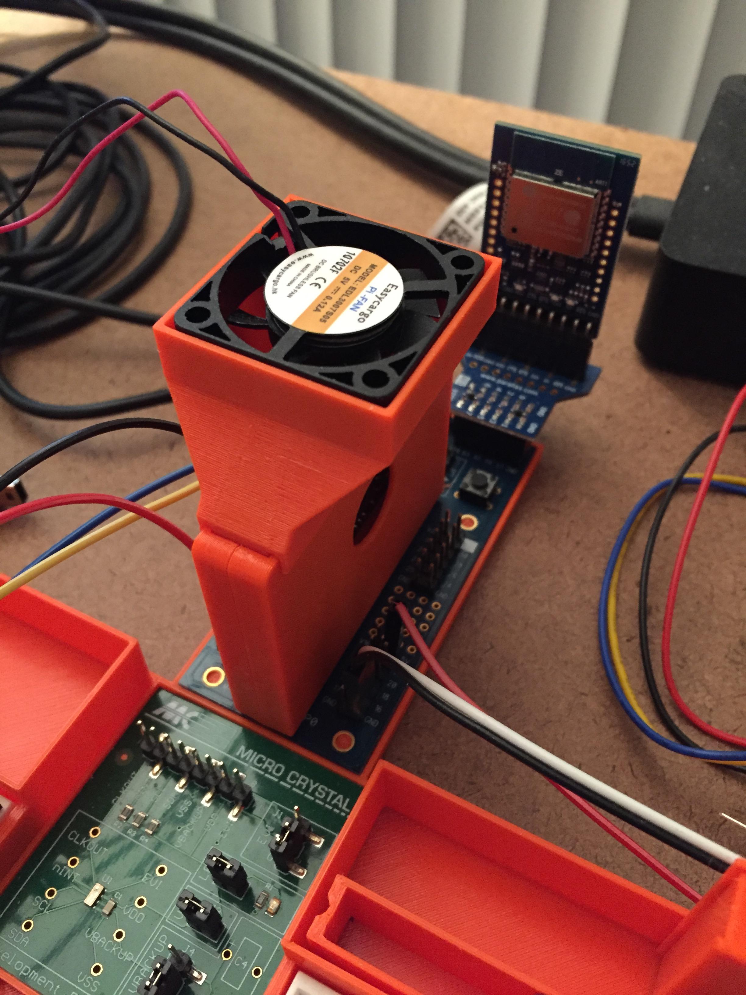
Preparing parts for the project A 3D printed holder. A heatsink
@rogloh said:
Works on the LCD panel, though the CRT doesn't like it too much. I do get an image there but the blanking seems a bit too low for it and there are some retrace artifacts. It would work fine on a twin LCD setup over DVI I suspect.
This works for both DVI and CRT monitors. Extremely tight for the CRT though:
svga_timing ' SVGA resolution 800x600 60Hz with 33MHz pixel clock
long CLK330MHz
long 330_000_000
'_HSyncPolarity___FrontPorch__SyncWidth___BackPorch__Columns
' 1 bit 7 bits 8 bits 8 bits 8 bits
long (SYNC_NEG<<31) | ( 16<<24) | (64<<16) | ( 16<<8 ) | (800/8)
'_VSyncPolarity___FrontPorch__SyncWidth___BackPorch__Visible
' 1 bit 8 bits 3 bits 9 bits 11 bits
long (SYNC_NEG<<31) | ( 1<<23) | ( 2<<20) | ( 11<<11) | 600
long 10 << 8
long 0
long 0 ' reserved for CFRQ parameter
Of note is the negative syncs. It seems to be important here that they both be negative for a CRT. I hadn't paid a lot of attention to this in the past but, looking back at what little history I do have, my best results have also been when using negative syncs.
Just been experimenting with 640x400 @ 70Hz and found I can go lower than the 8-64-8 minimum that I found was needed at higher resolutions. But, for CRT use, which this mode is meant to be good for also, 8-64-8 is ideal middle ground. And being 16:10 aspect, it's good middle ground there as well.
vga70_timing 'VGA resolution 640x400 70Hz with 25.0MHz pixel clock
long CLK250MHz
long 250_000_000
'_HSyncPolarity___FrontPorch__SyncWidth___BackPorch__Columns
' 1 bit 7 bits 8 bits 8 bits 8 bits
long (SYNC_NEG<<31) | ( 8<<24) | ( 64<<16) | ( 8<<8 ) | (640/8)
'_VSyncPolarity___FrontPorch__SyncWidth___BackPorch__Visible
' 1 bit 8 bits 3 bits 9 bits 11 bits
long (SYNC_NEG<<31) | ( 1<<23) | ( 2<<20) | ( 93<<11) | 400
long 10 << 8
long 0
long 0 ' reserved for CFRQ parameter
Roger,
Bah! I only just now worked out that leaving the CLKMODE parameter, in each timings structure, at zero invokes the auto calculate feature. I'd already gone to the trouble of hand crafting a bunch of mode lines at the top of the driver! Okay, I'm now setting everything that was preset to a clock mode to now being zero ... at least that's one irritation sorted with your driver.
What about the horrid list of display mode names as constants. Do those have to exist? The doubling up of two sets because of the text driver doesn't help. It's a pain having to search the source files to find out what name matches what set of timings.
Damn, there's some real Smile DVI LCD monitors in the wild. Just when we got flexible working ranges on CRTs they go and introduce LCDs that are fussy as all hell.
It's the weirdest thing really. This old DVI monitor is flexible enough, on DVI input, at more modern resolutions but when you try to throw an old PC mode at it, it has a fit if the scan frequencies aren't exactly right.
EDIT: No, that's not even 100% correct. The 640x400 mode above is way too high hfreq at 34.7 kHz but yet it works fine. Old PC mode was 31.5 kHz. Early fixed frequency CRTs had to have a single hfreq, VGA being 31.5 kHz.
@evanh said:
Roger,
Bah! I only just now worked out that leaving the CLKMODE parameter, in each timings structure, at zero invokes the auto calculate feature. I'd already gone to the trouble of hand crafting a bunch of mode lines at the top of the driver! Okay, I'm now setting everything that was preset to a clock mode to now being zero ... at least that's one irritation sorted with your driver.
Yes it use to annoy me too needing to do that, so that is why I automated it a while back and allow zero. So there is no need to create any more clkfreq constants unless you need precise control over its divisors and multipliers etc in the clock mode value.
What about the horrid list of display mode names as constants. Do those have to exist? The doubling up of two sets because of the text driver doesn't help. It's a pain having to search the source files to find out what name matches what set of timings.
Do you mean RES_640x480 etc? You don't need to change them in the driver, you add your own custom timings and pass those in the setup calls. These RES_xxx values are just to provide some stock timings for those people who just want to use standard resolution timings without needing to create their own first which can be tricky if you don't know what you are doing.
So really, you have several options here...
1) use one of the provided stock timings already built into the driver, eg:
either:
2) create some custom timing from specific parameters. You need to have the memory for the timing structure allocated in the caller and pass the address of this timing structure to the createCustomTiming method which will populate it appropriately - it also conveniently returns this same address, allowing this:
3) pass in your own custom timing structure directly, in the required format.
driver.initDisplay(cog, @display, output,basePin, syncPin, flags, lineBuf, linesize, @customTiming, 0, @region)
DAT
customTiming 'VGA resolution 640x400 70Hz with 25.0MHz pixel clock
long 0 ' optional clkmode value
long 250_000_000 ' P2 frequency value
'_HSyncPolarity___FrontPorch__SyncWidth___BackPorch__Columns
' 1 bit 7 bits 8 bits 8 bits 8 bits
long (driver.SYNC_NEG<<31) | ( 8<<24) | ( 64<<16) | ( 8<<8 ) | (640/8)
'_VSyncPolarity___FrontPorch__SyncWidth___BackPorch__Visible
' 1 bit 8 bits 3 bits 9 bits 11 bits
long (driver.SYNC_NEG<<31) | ( 1<<23) | ( 2<<20) | ( 93<<11) | 400
long 10 << 8 ' pixel clk divisor (either 8.8 fractional format in 16 bit LSW or as 32 bit XFRQ value)
'_Breezeway__C-Burst__FrontPorchHi__SyncWidthHi__BackPorchHi
' 8 bits 8 bits 8 bits 4 bits 4 bits
long 0 ' extensions to horizontal porches, breezeway and colour burst sizes for PAL/NTSC
long 0 ' CFRQ parameter for PAL/NTSC modulator
None of these options require you to change or add any timing structures in the driver which it seems you were doing.
As to why there are different names in the text driver vs lower level video driver, I am actually hoping to combine them to use the same set of regular names like (VGA,SVGA,XGA,WXGA,UXGA) in the next release. I just need to modify one of the VGA constants for the output type to RGB instead of VGA to avoid namespace collisions.
I am also thinking of allowing these names to be passed into the timing value for initDisplay() and my code would detect them to avoid needing to use RES_640x480 etc. I could do this if some upper bits were used to indicate the constant vs the address. This would eliminate the need to call getTiming(RES_800x600) etc (as done in case 1 above), and you could just do this which I think is probably the simplest it can be while remaining generic enough to cover all options needed:
Maybe forget the old monitors except for a few of the old PC modes like that one.
The newer cheapo LCD TV can take almost anything over HDMI. Even crazy low 512x320@75 and 480x270@75. Vfreq range is an impressive 24 Hz to 75 Hz. Just tested a 1280x800@32Hz using 350 MHz sysclock.
I've made a computeCustomDVI() function to quickly test whole ranges. First limit I hit is the timing structure has a limit of
9 bits for vertical back porch. Modern monitors can handle far greater vblank now.


Comments
Maybe you should do it when you port your SPIN2 compiler to the P2, now that there is a decent amount of ram.
Looks like a good example to start with for lots of projects.
Thanks, yes is it supplied with the drivers. I'm also experimenting with speeding up the text rendering stuff too. I think I just found a way to speed it up ~100x by writing to hub first one line of text at a time then doing a graphics copy.
Yes, that solved it.
Let me just say how great this driver package is.
Easy fiddling with screen timings, display regions and the memory functions make life so easy.
Using the "video" ram for other stuff without corrupting the display.... great
Now testing write/read(byte) functions with SRAM at various resolutions. P2@216Mhz -RES_1280x1024 still leaves a little bandwidth to do reads and writes to the sram :-)
Not much spare bandwidth is left at that resolution but its is still so much more than I could have hoped for!
And one could just hook up a second ram device if neccesary - very flexible
Yeah I like to keep things very flexible and fully featured, though packing everything into the space available often comes at the expense of more internal coding complexity making the code a bit tricky to decipher. My PASM2 drivers are probably not something for a new P2 user to easily learn from, but more to just use without knowing all the hidden details of how it works inside. I'm also still trying to wrap simpler SPIN2 APIs around them in more convenient ways....
When it comes to memory bandwidth if you probe the bus signals on a scope, specifically the memory CS pin and HSYNC pin, you will see the amount of memory bandwidth/time that the different video modes use and how much free time you get per scan line for all other lower priority requests, as well as the effect of the burst sizes and any resulting fragmented transfers. 1280x1024 is probably pushing things with the stock timing at 216MHz, but you could try to experiment with slightly higher P2 frequencies and more blanking if your monitor timing is flexible and you want more write bandwidth. Lower bit depths obviously help too.
Multiple devices on multiple buses are intended to work in this design...with concurrent requests on different buses. I'm still to really test that part out but it should work in theory. I should try it with my HyperRAM and PSRAM boards in a P2-EVAL sometime. Also Tubular mentioned trying out multiple display outputs sharing the same bank of external memory - and that might work too, assuming the same P2 clock frequency on each VGA and sufficient read/write bandwidth (ie. lower resolutions/bit depths). I think it would be best if the horizontal line frequencies remained in sync in that case so the requests responses were more deterministic.
I just tried this... and I'm now outputting video to both DVI and VGA on different ports from same PSRAM external frame buffer source and it appears to be working with a lot of write bandwidth left! This was tested with 640x480x8bpp and also 800x480x8bpp. Higher resolutions will push it harder but I don't have a twin VGA setup yet (needs some soldering of a board Tubular provided) such that I can output higher than VGA resolution yet. DVI is not syncing at 800x600x60Hz over DVI on my monitor as the dotclock is too high for the P2 TMDS output timing.
Here's a short (<2MB) video of the external RAM graphics demo now running on both screens.
The P2 Edge PSRAM is servicing two video COG requests per scan line, plus writing into the frame buffer from the lower priority COGs. Resolution here was 800x480x8bpp.
Wow, nice demo! Great to prove that is possible. Its useful that you tested 1 vga + 1 dvi as well.
Now to think of something to do with it... i guess stereo vision applications? Folding e-reader?
I discovered I have 2 types of these chips. "R" (these are the same as in P2 Edge 32MB) and (more of) "N". N cannot do bursts more than 1k...
I look forward to test this myself 👍
dvi60_800x600_timing ' 60 Hz with 33.0 MHz pixel clock long CLK330MHz long 330_000_000 '_HSyncPolarity___FrontPorch__SyncWidth___BackPorch__Columns ' 1 bit 7 bits 8 bits 8 bits 8 bits long (SYNC_NEG<<31) | ( 8<<24) | ( 64<<16) | ( 8<<8 ) | (800/8) '_VSyncPolarity___FrontPorch__SyncWidth___BackPorch__Visible ' 1 bit 8 bits 3 bits 9 bits 11 bits long (SYNC_NEG<<31) | (1<<23) | ( 2<<20) | ( 22<<11) | 600 long 10 << 8 ' sys-clock to pixel-clock ratio long 0 long 0 ' reserved for CFRQ parameterYeah your idea worked nicely Lachlan. Glad you suggested to try it out.
Works on the LCD panel, though the CRT doesn't like it too much. I do get an image there but the blanking seems a bit too low for it and there are some retrace artifacts. It would work fine on a twin LCD setup over DVI I suspect.
Hehe, yeah, fully reduced h-blanking. Only intended for digital links like DVI/HDMI.
Here's a simple script I've written to fill PSRAM with a file:
loadit.rb:COMPORT = 'COM7' SLICE_SIZE = 256*1024 require 'tempfile' `flexspin -2 psram_loadit.spin2` raise "Need exactly one argument" if ARGV.size != 1 thefile = File.binread(ARGV[0]) totalslices = ((thefile.size-1)/SLICE_SIZE)+1 i = 0 until thefile.empty? puts "Loading slice #{i}..." tmp = Tempfile.new("loadit", binmode: true) tmp.write(i.chr) tmp.write(totalslices.chr) tmp.write(thefile.slice!(0...SLICE_SIZE).ljust(SLICE_SIZE,?\0)) tmp.close `loadp2 -p #{COMPORT} @0=psram_loadit.binary,@7FFE=#{tmp.path} -e "recv(E)"` tmp.unlink i+=1 endpsram_loadit.spin2:CON _CLKFREQ = 300_000_000 _STACK = 128 _FREE = ((512-32)*1024)/4 + 1 SLICE_MAX = (32*1024*1024)/(256*1024) OBJ ram:"psram" PUB main() | slice, total slice:= byte[$7FFE] total:= byte[$7FFF] ram.start() repeat ram.write($8000,slice*(256*1024),256*1024) while (slice+=total)<SLICE_MAX _tx("E") repeatGreat, looks handy.
I just used Wuerfel's ruby download tool above and loaded a 1024x768 truecolour image into the PSRAM framebuffer for output with my video driver. This is probably somewhere around the highest (common) resolution possible with truecolour and external memory bandwidth available (at 60Hz). It worked. Ignore the banding video artefact at the top due to photographing the CRT. Earlier I did see one time when a single downloaded slice seemed to be corrupted so not sure what happened there if it failed to download that portion (the download might have timed out, script doesn't stop on failure).
Edge is pretty warm to hold, P2 running at 325MHz..three cogs active (one in an empty repeat loop).
Amiga type HAM is worth to consider in such environment. I t can give a lot of colors while still being 8bpp.
Just managed to push the truecolour framebuffer output out at 1280x720@60Hz to a CRT via VGA. That works too and is more pixels than 1024x768 so I was incorrect above. Not going to be a huge amount of write bandwidth left with that but it does work and could be rather useful for slideshows etc. It runs at 297MHz.
I also tried 1080i60 but (for integer pixel clock ratios) I think it needs to run the P2 at 371.25MHz which is a bit too high (even though it worked!). 1080i50 should be achievable with truecolour output at more reasonable P2 clock speed. I need to dig up the official 1080i50 timing to test that one out properly.
Interestingly... One of the manufacturing tests for the modules runs them at 370MHz, but I'd expect the modules to get warm/hot over time at that level of overclocking (depending on the power demands of users code).
Probably would be good to have a fan or heatsink to control the temperature rise of the module when the user code is pushing things at such limits! At least for long term use.
I was thinking of @CJMJ 3D printed module holder... maybe that could have a small fan attached to the back for overclocking experiments in a convenient form factor....
Oh, @VonSzarvas, I almost forgot: The Edge product guide has the PSRAM clock and select pins swapped around.
Fix queued for deployment. Thank you very much.
Preparing parts for the project") A 3D printed holder. A heatsink
A 3D printed holder. A heatsink ")
Cool!
How about this? I call it a FanShell. I'll put it under it own thread "P2 FanShell".
This works for both DVI and CRT monitors. Extremely tight for the CRT though:
svga_timing   ' SVGA resolution 800x600 60Hz with 33MHz pixel clock
            long   CLK330MHz
            long   330_000_000
                   '_HSyncPolarity___FrontPorch__SyncWidth___BackPorch__Columns
                   '     1 bit         7 bits      8 bits      8 bits    8 bits
            long   (SYNC_NEG<<31) | ( 16<<24) | (64<<16) | ( 16<<8 ) | (800/8)

                   '_VSyncPolarity___FrontPorch__SyncWidth___BackPorch__Visible
                   '     1 bit         8 bits      3 bits      9 bits   11 bits
            long   (SYNC_NEG<<31) | (  1<<23) | (  2<<20) | ( 11<<11) | 600
            long    10 << 8
            long    0
            long    0   ' reserved for CFRQ parameter
Of note is the negative syncs. It seems to be important here that they both be negative for a CRT. I hadn't paid a lot of attention to this in the past but, looking back at what little history I do have, my best results have also been when using negative syncs.
Just been experimenting with 640x400 @ 70Hz and found I can go lower than the 8-64-8 minimum that I found was needed at higher resolutions. But, for CRT use, which this mode is meant to be good for also, 8-64-8 is ideal middle ground. And being 16:10 aspect, it's good middle ground there as well.
vga70_timing 'VGA resolution 640x400 70Hz with 25.0MHz pixel clock long CLK250MHz long 250_000_000 '_HSyncPolarity___FrontPorch__SyncWidth___BackPorch__Columns ' 1 bit 7 bits 8 bits 8 bits 8 bits long (SYNC_NEG<<31) | ( 8<<24) | ( 64<<16) | ( 8<<8 ) | (640/8) '_VSyncPolarity___FrontPorch__SyncWidth___BackPorch__Visible ' 1 bit 8 bits 3 bits 9 bits 11 bits long (SYNC_NEG<<31) | ( 1<<23) | ( 2<<20) | ( 93<<11) | 400 long 10 << 8 long 0 long 0 ' reserved for CFRQ parameterRoger,
Bah! I only just now worked out that leaving the CLKMODE parameter, in each timings structure, at zero invokes the auto calculate feature. I'd already gone to the trouble of hand crafting a bunch of mode lines at the top of the driver! Okay, I'm now setting everything that was preset to a clock mode to now being zero ... at least that's one irritation sorted with your driver.
What about the horrid list of display mode names as constants. Do those have to exist? The doubling up of two sets because of the text driver doesn't help. It's a pain having to search the source files to find out what name matches what set of timings.
Damn, there's some real Smile DVI LCD monitors in the wild. Just when we got flexible working ranges on CRTs they go and introduce LCDs that are fussy as all hell.
It's the weirdest thing really. This old DVI monitor is flexible enough, on DVI input, at more modern resolutions but when you try to throw an old PC mode at it, it has a fit if the scan frequencies aren't exactly right.
EDIT: No, that's not even 100% correct. The 640x400 mode above is way too high hfreq at 34.7 kHz but yet it works fine. Old PC mode was 31.5 kHz. Early fixed frequency CRTs had to have a single hfreq, VGA being 31.5 kHz.
Yes it use to annoy me too needing to do that, so that is why I automated it a while back and allow zero. So there is no need to create any more clkfreq constants unless you need precise control over its divisors and multipliers etc in the clock mode value.
Do you mean RES_640x480 etc? You don't need to change them in the driver, you add your own custom timings and pass those in the setup calls. These RES_xxx values are just to provide some stock timings for those people who just want to use standard resolution timings without needing to create their own first which can be tricky if you don't know what you are doing.
So really, you have several options here...
1) use one of the provided stock timings already built into the driver, eg:
either:
or combined in the same call:
2) create some custom timing from specific parameters. You need to have the memory for the timing structure allocated in the caller and pass the address of this timing structure to the createCustomTiming method which will populate it appropriately - it also conveniently returns this same address, allowing this:
3) pass in your own custom timing structure directly, in the required format.
driver.initDisplay(cog, @display, output,basePin, syncPin, flags, lineBuf, linesize, @customTiming, 0, @region)

DAT
customTiming      'VGA resolution 640x400 70Hz with 25.0MHz pixel clock
            long   0 ' optional clkmode value
            long   250_000_000 ' P2 frequency value
                        '_HSyncPolarity___FrontPorch__SyncWidth___BackPorch__Columns
                        '     1 bit         7 bits      8 bits      8 bits    8 bits
            long   (driver.SYNC_NEG<<31) | ( 8<<24) | ( 64<<16) | ( 8<<8 ) | (640/8)

                        '_VSyncPolarity___FrontPorch__SyncWidth___BackPorch__Visible
                        '     1 bit         8 bits      3 bits      9 bits   11 bits
            long   (driver.SYNC_NEG<<31) | ( 1<<23) | (  2<<20) | ( 93<<11) | 400
            long   10 << 8  ' pixel clk divisor (either 8.8 fractional format in 16 bit LSW or as 32 bit XFRQ value)
                '_Breezeway__C-Burst__FrontPorchHi__SyncWidthHi__BackPorchHi
                '  8 bits     8 bits     8 bits        4 bits        4 bits
            long   0   '  extensions to horizontal porches, breezeway and colour burst sizes for PAL/NTSC
            long   0   '  CFRQ parameter for PAL/NTSC modulator
None of these options require you to change or add any timing structures in the driver which it seems you were doing.
As to why there are different names in the text driver vs lower level video driver, I am actually hoping to combine them to use the same set of regular names like (VGA,SVGA,XGA,WXGA,UXGA) in the next release. I just need to modify one of the VGA constants for the output type to RGB instead of VGA to avoid namespace collisions.
I am also thinking of allowing these names to be passed into the timing value for initDisplay() and my code would detect them to avoid needing to use RES_640x480 etc. I could do this if some upper bits were used to indicate the constant vs the address. This would eliminate the need to call getTiming(RES_800x600) etc (as done in case 1 above), and you could just do this which I think is probably the simplest it can be while remaining generic enough to cover all options needed:
Maybe forget the old monitors except for a few of the old PC modes like that one.
The newer cheapo LCD TV can take almost anything over HDMI. Even crazy low 512x320@75 and 480x270@75. Vfreq range is an impressive 24 Hz to 75 Hz. Just tested a 1280x800@32Hz using 350 MHz sysclock.
I've made a
computeCustomDVI()function to quickly test whole ranges. First limit I hit is the timing structure has a limit of9 bits for vertical back porch. Modern monitors can handle far greater vblank now.