

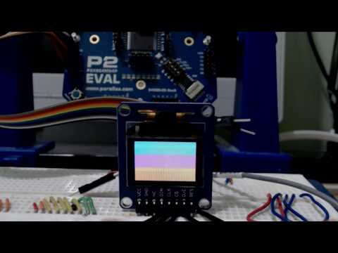
P2 running the Parallax "96 x 64 Color OLED Display Module" Product ID: 28087 - SSD1331
 ke4pjw
Posts: 1,334
ke4pjw
Posts: 1,334
Development of this project has been moved to Azure DevOps
https://griswoldfx.visualstudio.com/P2 SSD1331
Repo can be found here: https://griswoldfx.visualstudio.com/_git/P2 SSD1331
https://griswoldfx.visualstudio.com/P2 SSD1331
Repo can be found here: https://griswoldfx.visualstudio.com/_git/P2 SSD1331
Comments
I would appreciate some help in someone pointing me to where to read in the P2 manual about smartpin transfer speeds. I was under the impression that the smartpins were bound to the clock speed. This one is operating at 24KHz.
Which mode ?
Async ones say this
"WXPIN is used to configure the baud rate and word length.
X[31:16] establishes the number of clocks in a bit period, and in case X[31:26] is zero, X[15:10] establishes the number of fractional clocks in a bit period. The X bit period value can be simply computed as: (clocks * $1_0000) & $FFFFFC00. For example, 7.5 clocks would be $00078000, and 33.33 clocks would be $00215400.
X[4:0] sets the number of bits, minus 1. For example, a value of 7 will set the word size to 8 bits.
"
Sync mode says this
"Words of 1 to 32 bits are shifted out on the pin, LSB first, with each new bit being output two internal clock cycles after registering a positive edge on the B input. For negative-edge clocking, the B input may be inverted by setting B[3] in WRPIN’s D value.
"
ie you need to create (or input) a clock on the B-Pin mapping, and that sets the baud rate
For the synchronous serial, you need to generate the clock, ideally using a smart pin.
Yes, only the clock timing is done in the clock-pin setup, not in the sync-shifter pin setup.
You can ask for any clock up to SysCLK/2 onto a pin.
Which mode does your clock smart pin use ?
I will need to unpack that from the code. I pulled from examples that other forum members have given me. Quite frankly, the only thing I changed was to shift on a negative clock. The documentation isn't clear how bit period is configured for sync serial. Based on what you posted above, I think I know what I need to do!
I calculate the above from 24000 x 4096 x 2. The 2 is because two clock transitions per bit. 4096 because that's the transition period set on line 468 of test_AsmDrv.spin2.
As for the system clock setting. You've made an error in comments of _XDIV, a value of 2 gives 10 MHz, not 5. This has caused incorrect calculation for the other components. Also, I'd recommend leaving _XDIVP = 1 unless going below 20 MHz. I know the docs say 100 MHz but that's a hugely conservative number.
I removed some of the unnecessary waits I added in the TX code. I had to add waits to the clear screen. My code would start sending data before the RAM on the display could finish it's task after a clearDisplay sequence was sent.
I will try to clean this code up soon.
Thanks for everyone's help.
PS: I updated the video so you can see the end result. We might be able to implement a screen buffer on this bad boy! It's fast!
If you overclock it will it take off?
Fastspin started segfaulting if the program was over 300K, so I was limited to 24 frames.
Please don't look at the code. Zero cleanup. This was my first time using raw pixel data vs 16bit 565 bmp, so the offset is set to 0.
Do you notice tearing when playing your video?
I think I see some in your video, but hard to tell...
It's too bad none of these displays bring out the "FR" signal that would let you sync to the device...
It appears that up to ~60 fps is possible over SPI, if I'm reading the datasheet right...
I will have to go back and look at my captures from the logic analyzer and see if there are gains that can be had tweaking the smartpins. I seem to recall I was clocking out at 25Mhz, but there were large gaps between the bytes. The buffer was a single frame as I recall. I do not recall that gaps between the frames. I was just thrilled to get it going
@cheezus updated his SD driver, which I use to pull the video from, so there may be some gains to be had there as well.
When the P2ES2 is available, I am going to jump back into this.
So, almost 2.5 years later, I am looking at this again")
We now have an official spin2 from parallax and Eric's compiler is more aligned with that now. Also, this was developed on the Rev. A silicon.
I am going to go through this code and update it to the modern spin2 implementation. I need a short break from the W6100 ethernet project and this will give me a helpful distraction.
I was able to get this to compile without warnings in FlexProp and it works as expected. Unfortunately, I cannot get it to work in PropTool, yet.
Current code is attached at the top of this thread. If anyone has this hardware and wants to have a look at the code to see why it does not work in PropTool, that would be much appreciated. There are also bugs listed above.
Breaktime is over, back to working on the W6100")
Is the PropTool problem functional issues or are we talking compile errors? Is it worth someone without the hardware looking at the problem?
@evanh It compiles, but there is no visible output on the display. I have not broken out the logic analyzer to see if it has a pulse. There is a lot of non-standard syntax in there and holdovers from back when we only had flexgui and peanut. I suspect the cog isn't starting, or something like that. It's worth a look. Probably something silly.
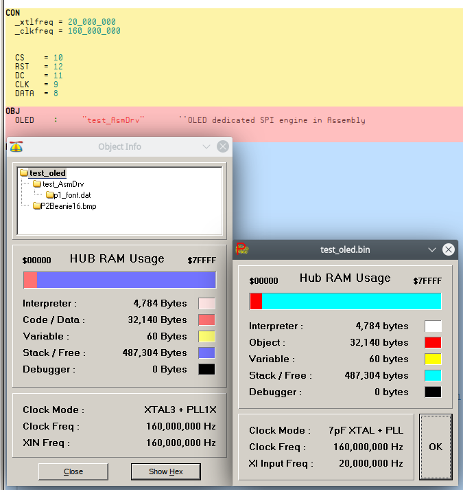
Okay, had a look ... weird, PropTool is confused, somehow it thinks it's a Prop1 program. Even weirder is it happily appends .spin2 to the AsmDrv filename.
Check out the difference here between PropTool 2.6 on the left and PNut 35 on the right:
BTW: I've made some changes to clock setting. Namely removed 100% of it and just let the
_clkfreqconstant do its thing instead.Here's my hack. It might work with the hardware.
That was a good find. However, it still only works in FlexProp. I appreciate you looking at it!
PropTool is behaving weirdly. Give PNut a shot.
Oh, the COGINIT() needs fixed too. It should be requesting a free cog rather than specifying a particular number:
PUB start():okay

'' Start SPI Engine - starts a cog
'' returns false if no cog available
    stop()
    okay := cog := coginit(COGEXEC_NEW,@main, @command) + 1
Actually, commanding the display could really just be some sub-routines. No need for a whole cog to do it.
I have thought about reworking it that way. At the time I was just using the old paradigm. Would be really easy with inline PASM2. I might just do that instead.
No dice with changing to dynamic cog allocation.