

P2 smart pin drive class-e amplifier
 iammegatron
Posts: 40
iammegatron
Posts: 40
in Propeller 2
I am trying to use P2 smart pin to control a simple class-e amplifier circuit (schematic below)
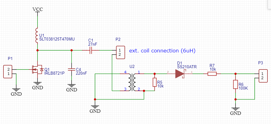
Smart pin generates PWM pulse with fixed duty cycle to drive the gate of Q1 transistor (at P1).
U2 is a current transformer to sense the current in an external coil. The voltage waveform at P3 node is sinusoidal (rectified).
The idea is to hit Q1 at zero crossing of the waveform at P3.
Is there a "feedback" mode, where one smart pin ADC a sin-wave, and when it detects zero crossing of the signal, fires up another smart pin for a pulse.
Comments
ADC is sigma-delta so will have notable response lag.
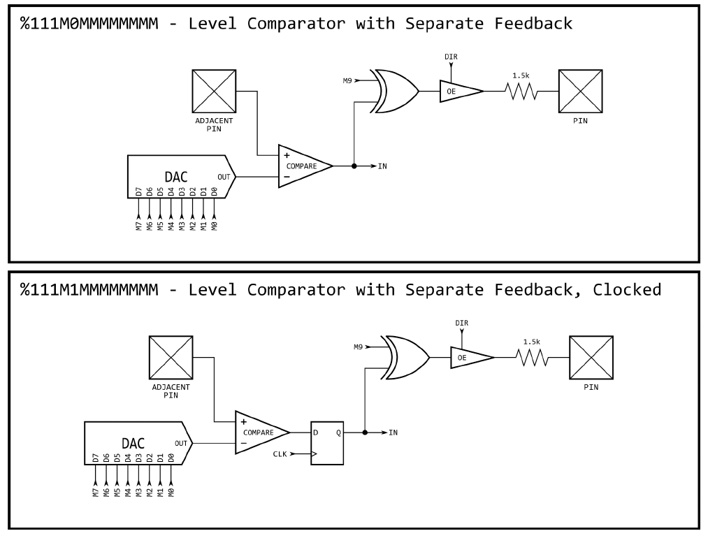
What might be effective is the analogue comparator. It has programmable 8-bit DAC for threshold. It can be configured to compare 8-bit DAC with partner pin, and result fed straight back to the output drive. All in the low-level pin circuits.
The silicon doc has diagrams of low-level modes - https://www.parallax.com/propeller-2/documentation/
PIN and ADJACENT PIN are odd/even pairs. If PIN is even (eg: Pin P0) then ADJACENT is odd (Pin P1), and vice versa.
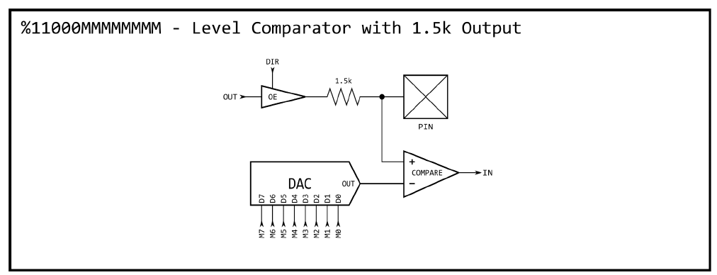
Oops, here's the internal DAC option:
Note: It's limited to 1k5R output drive strength. This was due to limited config bits in the pin mode word. The lower 8 bits are the DAC value, whereas they are drive strength in the non-DAC config.
EDIT: Hmm, The diagram for "clocked" has the flip-flop in the wrong place. It should be after the XOR. Further reading - https://forums.parallax.com/discussion/comment/1494131/#Comment_1494131 EDIT2: Scratch that. I remember now, it's an abbreviation of two flops in parallel.
If you're keen to fast process ADC data then there is features for that too. There's something called the DDS/Goertzel streamer mode. I've not delved into it, it's over my head really. It has a feature for processed feedback to the DACs.
Ah, what you may want is one of the smartpin modes. A particular one that is PWM output and uses inputs for feedback, namely
P_PWM_SMPS- PWM switch-mode power supply I/O, mode number %01010. This can still have comparator inputs, two of them, but unlike above output is regular drive on its own.Hmm. This may be obvious to others (and discussed elsewhere) but it strikes me that if you already know, to a rough approximation, what the ADC voltage is going to be, it might be much faster to just hammer away at the comparator's DAC threshold settings than wait for the sigma-delta ADC to get there from zero. I dunno, just curious. Thanks. S.
Yup, I'm thinking that that PWM smartpin mode is what he wants. It fits perfectly with using DAC set level comparators on it's inputs.
Use this pin mode, with the outputs disabled, on two nearby pins for smartA and SmartB inputs:
SmartA/B inputs on this smartpin for the PWM output:
Updated link: General diagram of I/O routing here - https://forums.parallax.com/discussion/comment/1530931/#Comment_1530931
@evanh Thanks for your reply.
Sorry, I am still getting up to speed with smartpins. Here is my next question:
I can use (%01001: PWM sawtooth) to generate a pulse to trigger the transistor.
And (%11000 ) allows me to input a voltage from P3 (current monitor) and get a comparator output, which is good for zero-crossing check. (It gets triggered two times because the diode folds up the sin-wave.)
I am still puzzled how to tie these two together.
Have a read of the smartpin section in the hardware "silicon" manual. The full WRPIN mode word contains 32 bits. The smartpin section is in the low bits, %SSSSS and %TT, whereas the low-level pin mode bits are mid range, %MMMMMMMMMMMMM. There is also other bits for routing and de-glitching the input sources: %AAAA, %BBBB, %FFF.
PS: There is some lack of clarity in distinguishing between pin modes and smartpin modes.
PPS: The Spin2 doc contains convenient predefined constants for the mode fields. eg:
    wrpin( pwmpin+1, P_LEVEL_A| (10<<8) )    'zero-crossing input.  A low threshold of 10 chosen.
    wrpin( pwmpin+2, P_LEVEL_A| (255<<8) )    'over-current detection. (max 255)
    pinstart( pwmpin, P_PWM_SMPS|P_OE|P_PLUS1_A|P_PLUS2_B, ten_usec, 0 )    'uses pin+1 for inputA, and pin+2 for inputB
WRPIN() translates to a simple WRPIN instruction, the low-level pin modes don't retain state data so can switch modes on a dime.
PINSTART() is a specific sequence of DIRL->WRPIN->WXPIN->WYPIN->DIRH. This sequence is basic requirement to cleanly initialise a smartpin.
If that smartpin mode isn't suitable then to use a simpler PWM mode would be via software ... pin setup isn't that different:
    wrpin( pwmpin+1, P_LEVEL_A| (10<<8) )    'zero-crossing input.  A low threshold of 10 chosen.
    pinstart( pwmpin, P_PWM_SAWTOOTH|P_OE, ten_usec, 0 )
There is a lag issue to consider - The smartpin's Y register is a buffer. Where the docs say "captured", that is talking about moving the buffered value from the buffer register, Y in this case, into the matching live PWM register. Which, of course, happens upon starting the subsequent PWM cycle. This provides nice clean cycles without tying up the CPU to time it just right.
So, if wanting to override that hardware feature for faster response, things start to get drastic. Like disabling the output drive or the smartpin itself even.