

WT901cTTL IMU testing with output to DEBUG Artificial Horizon and yaw, pitch, roll stepper motors
 mwroberts
Posts: 97
mwroberts
Posts: 97
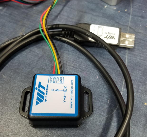
I bought this WT901cTTL on Amazon for about $30. along with the $20.usb cable for configuring it .
It outputs yaw, pitch and roll data at up to 200Hz. It will also output quaternions.
I configured it using the wit-motion app to output just yaw, pitch and roll data at 100Hz,115200baud.
Yaw was a bit weird until I calibrated the magnetometer using the app also.
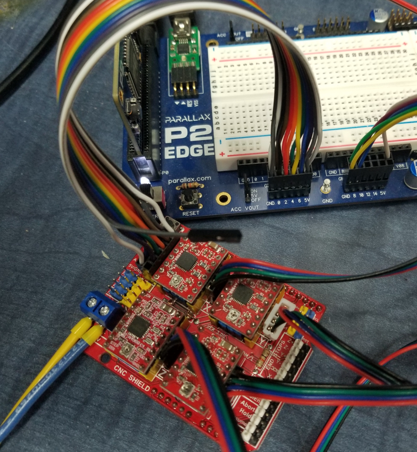
Arduino stepper motor shields and A4988 stepper drives are super cheap on Amazon, and they wire directly up to the propeller 2.
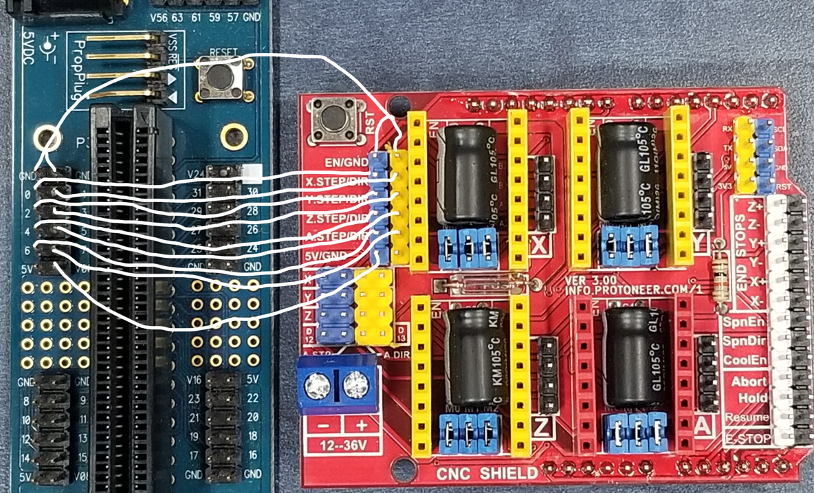
The A4988 stepper motor driver logic run off of 3.3v and you can apply 3.3v to the arduino stepper motor shield at the 5v pin and it will power the A4988's just fine... Of course it also needs the 12v supply for powering the motors... Attached in a snip is a wiring diagram.
The code is short and all in spin... It uses the JM_fullduplexserial object.
It runs in a 100Hz loop, paced by the output of the accelerometer.
Debug updates at 10Hz.
It will also read a BNO080 in RVC mode if the config bit is set instead of the WT901cTTL.
Stepper driver code is very small and simple using smartpins.
A numeric controlled oscillator smartpin to output velocity to the stepper drive,
A step/dir smartpin counter to keep track of stepper position
https://youtube.com/watch?v=NyGUiV2ovuE
wit_motion_try2{ read yaw pitch and roll from wit motion wt901 cttl module}


CON
  CONSTANT_NAME = 0

    _clkfreq = 200_000_000
    baud = 115200
    BNO080 = false     'else WT901cTTL
VAR
  long sample
  long i,j
  long count,oldcount,et
  long roll,pitch,yaw
  long x1,x2,y1,y2
  long oldx1,oldx2,oldy1,oldy2
  long zeroed, offsetroll, offsetpitch
  long Xpos,Ypos,Zpos,Xvel,Yvel,Zvel
  long dX,dY
  byte  c
  byte  byte1,byte2,byte3,byte4,byte5,byte6,byte7,byte8,byte9,byte10,byte11
  byte  pitchLow,pitchHi,yawLow,yawHi,rollLow,rollHi

OBJ
   term : "jm_fullduplexserial"
   fmt  : "jm_nstr"


PUB main()
    SetSmartPinsB()
   debug(`plot myplot pos 2200 200 color blue TITLE 'Artificial Horizon' )
   debug(`TERM MyTerm pos 1500 50 SIZE 80 40  TEXTSIZE 10)

     if BNO080
        term.start(26,27,0,baud) 'BNO080
     else
        term.start(24,25,0,baud) 'wt901cttl

    debug(`myplot color $f0f0f0 set (150,30) circle 12,12 )
    debug(`myplot color white set (150,30) circle 8,8 set (200,30) color white TEXTSTYLE %00110001  text 10 'BNO080)
    debug(`myplot color $f0f0f0 set (150,50) circle 12,12 )
    debug(`myplot color white set (150,50) circle 8,8 set (220,50) color white text 10 'WT901cTTL)

  repeat                      'packets of data come in 100x's per second
    repeat while et < 80_000  'this waits for the time gap between packets, first byte after the time gap is the first in the packet
      oldcount := getct()
      byte1 := term.rx()
      count := getct()
      et := count-oldcount

    byte2,byte3,byte4,byte5 := term.rx(),term.rx(),term.rx(),term.rx()
    byte6,byte7,byte8,byte9 := term.rx(),term.rx(),term.rx(),term.rx()
    et := 0
    sample++

    if BNO080
      rollLow,rollHi,pitchLow,pitchHi,yawLow,yawHi := byte8,byte9,byte6,byte7,byte4,byte5
    else
      rollLow,rollHi,pitchLow,pitchHi,yawLow,yawHi := byte3,byte4,byte5,byte6,byte7,byte8

    roll,pitch,yaw  := ( rollLow + rollHi<<8 ) signx 15, ( pitchLow + pitchHi<<8 ) signx 15,( yawLow + yawHi<<8 ) signx 15

    if !!zeroed
      offsetroll,offsetpitch := -roll, -pitch
      zeroed := true

    roll,pitch := roll + offsetroll,pitch+offsetpitch

    dX,dY :=polxy(75,pitch*50000)  'debug Plot artificial horizon stuff
    x1,y1,x2,y2 :=125  - dx,125  + dy  + roll/100,125  + dx,125  - dy  + roll/100

    Xpos := RQPIN(1) *10        'smartpin is counting step/dir pulses and keeping track of motor position (assuming no stalling)
    Ypos := RQPIN(3) *10
    Zpos := RQPIN(5) *10

    ''Xvel,Yvel,Zvel := roll,pitch,yaw                       'command a velocity proportional to position

    Xvel,Yvel,Zvel := roll-Xpos,pitch-Ypos,yaw-Zpos         'command a velocity that is proportional to the position error

    if Xvel<0                  'set Direction pin for x stepper drive
      PinLow(1)
    else
     PinHigh(1)
    WYPIN(0, abs(Xvel)*10000)  'write pulse rate to Numeric controlled oscillator

    if Yvel<0
      PinLow(3)
    else
     PinHigh(3)
    WYPIN(2, abs(Yvel)*10000)

    if Zvel<0
      PinLow(5)
    else
     PinHigh(5)
    WYPIN(4, abs(Zvel)*10000)


    if !!(sample//5) 'every 10 samples which is 10x's per second
      debug(`MyTerm 0 '`(roll) `(pitch) `(yaw) `(sample)' )
      debug(`MyTerm 10 '`(Xpos) `(Ypos) `(Zpos) `(dX) `(dY)' )
      debug(`myplot color black set `(oldx1,oldy1) line `(oldx2,oldy2,3) )
      debug(`myplot color green set `(x1,y1) line `(x2,y2) )
      oldx1,oldx2,oldy1,oldy2 := x1,x2,y1,y2


PRI SetSmartPinsB()| x

    '==X Axis=====
    x := $0000__00C8 ' 200_000_000/200 = 1uSec base period at 200Mhz clk, good for A4988 but DRV8825 needs 2uSec min pulse width
    pinstart(0,P_LOCAL_A| P_PLUS1_B| P_OE | P_NCO_DUTY, x, 0)   'smartpin for pulses to stepper drive x pin 0 "step" input
    pinstart(1, P_MINUS1_A | P_LOCAL_B | P_OE | P_REG_UP_DOWN , 0, 0)   'smartpin = 1, $70 works, and $74 works also "dir" input
    'pinstart(1, P_MINUS1_A | P_INVERT_B | P_LOCAL_B | P_OE | P_REG_UP_DOWN , 0, 0)   'smartpin = 1, $70 works, and $74 works also "dir" input
    '==Y Axis=====
    x := $0000__00C8 ' 200_000_000/200 = 1uSec base period at 200Mhz clk, good for A4988 but DRV8825 needs 2uSec min pulse width
    pinstart(2,P_LOCAL_A| P_PLUS1_B| P_OE | P_NCO_DUTY, x, 0)   'smartpin for pulses to stepper drive x pin 0 "step" input
    pinstart(3, P_MINUS1_A | P_LOCAL_B | P_OE | P_REG_UP_DOWN , 0, 0)   'smartpin = 1, $70 works, and $74 works also
    '==Z Axis=====
    x := $0000__00C8 ' 200_000_000/200 = 1uSec base period at 200Mhz clk, good for A4988 but DRV8825 needs 2uSec min pulse width
    pinstart(4,P_LOCAL_A| P_PLUS1_B| P_OE | P_NCO_DUTY, x, 0)   'smartpin for pulses to stepper drive x pin 0 "step" input
    pinstart(5, P_MINUS1_A | P_LOCAL_B | P_OE | P_REG_UP_DOWN , 0, 0)   'smartpin = 1, $70 works, and $74 works also
    '==A Axis=====
    x := $0000__00C8 ' 200_000_000/200 = 1uSec base period at 200Mhz clk, good for A4988 but DRV8825 needs 2uSec min pulse width
    pinstart(6,P_LOCAL_A| P_PLUS1_B| P_OE | P_NCO_DUTY, x, 0)   'smartpin for pulses to stepper drive x pin 0 "step" input
    pinstart(7, P_MINUS1_A | P_LOCAL_B | P_OE | P_REG_UP_DOWN , 0, 0)   'smartpin = 1, $70 works, and $74 works also
    '==B Axis=====
    x := $0000__00C8 ' 200_000_000/200 = 1uSec base period at 200Mhz clk, good for A4988 but DRV8825 needs 2uSec min pulse width
    pinstart(8,P_LOCAL_A| P_PLUS1_B| P_OE | P_NCO_DUTY, x, 0)   'smartpin for pulses to stepper drive x pin 0 "step" input
    pinstart(9, P_MINUS1_A | P_LOCAL_B | P_OE | P_REG_UP_DOWN , 0, 0)   'smartpin = 1, $70 works, and $74 works also

   ' pinstart(pin2,P_MINUS2_A| P_MINUS2_B| P_PERIODS_TICKS, 1, 0)   'pin2 smartpin to read clk cnts between step pulses on pin 0 "step" input
                                                                    'If you use this, this pins 2&3 can't be used as a stepper driver pair
Comments
Nice work! I have a question that might be a bit off-topic because it has nothing to do with the hardware or software but is more about how those sensors work in theory.
Because I read the words "artificial horizon"... Is the display just reading the direction of the gravity vector or does it a "real" integration of the acceleration forces to calculate yaw, pitch and roll relative to an absolute system?
The first method works as long as there are no considerable centrifugal forces generated by rotation around an external center point. But as soon as your vehicle is flying a circular or spiral trajectory the gravity vector can't be distinguished from the centrifugal forces if you only watch the linear components of acceleration (3DOF). You need to also measure the rotational accelerations (6DOF) and double integrate them to get rotational position which is very sensitive to drift.
As a magnetometer is mentioned I guess that is used as a compass to calibrate the drift of the angular velocity. So could this device be used as an artifical horizon in a real aircraft? (only theoretically, of course, I'm no suicidal )
)
I have used the BNO080 units that work the same way and they do rely on the compass to get accurate yaw. They work as long as you're not near a metal or magnetic source. At about $20 theses unit are nice.
I also like the TMC2208 units from Trinamic that work just like the A4988 units but are so much quieter in operation.
Mike
@ManAtWork Thanks, My understanding of the WT901is that it uses all three, the gyros, accelerometers and magnetometer, and "fuses" them together into a yaw, pitch roll solution that best satisfies what is sees from the inputs...
Before I calibrated the unit, when I rotated it in the yaw direction, the yaw stepper would quickly follow the motion, then slowly creep back a fair amount, I think the yaw gyro gain was to high and the magnetometer outputs at a lower bandwidth...
From the wit-motion page on this WT901
"WT901’s scientific name is the AHRS IMU sensor. A sensor measures 3-axis angle, angular velocity, acceleration, magnetic field. WitMotion WT901 integrates a high-precision gyroscope, accelerometer, and geomagnetic field sensor, and adopts a high-performance microprocessor, advanced dynamics fusion algorithm, and Kalman dynamic filtering algorithm to quickly analyze the module's current real-time motion posture.
With its in-built posture solver and the dynamic Kalman filter algorithm, the sensor can accurately output the current posture of the product in a dynamic environment. The measurement accuracy of the X and Y axis can reach 0.05°, and the stability is extremely high.
State estimation algorithm: Time and energy saving: No need to write a filtering program or study the complicated protocol of MPU6050/ 9250 to analyze and collect the attitude angle data."
About a year ago I wrote propeller code to read the gyros, accelerometers and magnetometer output from a LSM9DS1, and that all worked, but after a week I gave up on trying to "integrate" it into a attitude solution... you needed to do a 3d rotation between integrations periods because the local xyz frame was moving relative to the North-East-Down frame...
@iseries The BNO080 units are getting hard to find, I fear they may not be making them anymore... I Will try the TMC2208...
I think your right, I purchased the FSM300 from Hillcrest Labs which works the same as the BNO085.
Mike
Thanks for the explanation. It would be really funny to build an actual artificial horizon device and test it riding a bicycle driving circles...